EP1787376B1 - Charge electrique ou dispositif d'alimentation - Google Patents
Charge electrique ou dispositif d'alimentation Download PDFInfo
- Publication number
- EP1787376B1 EP1787376B1 EP05773139A EP05773139A EP1787376B1 EP 1787376 B1 EP1787376 B1 EP 1787376B1 EP 05773139 A EP05773139 A EP 05773139A EP 05773139 A EP05773139 A EP 05773139A EP 1787376 B1 EP1787376 B1 EP 1787376B1
- Authority
- EP
- European Patent Office
- Prior art keywords
- connectors
- electrical
- power supply
- casing
- electrical apparatus
- Prior art date
- Legal status (The legal status is an assumption and is not a legal conclusion. Google has not performed a legal analysis and makes no representation as to the accuracy of the status listed.)
- Expired - Lifetime
Links
Images


Classifications
-
- H—ELECTRICITY
- H01—ELECTRIC ELEMENTS
- H01R—ELECTRICALLY-CONDUCTIVE CONNECTIONS; STRUCTURAL ASSOCIATIONS OF A PLURALITY OF MUTUALLY-INSULATED ELECTRICAL CONNECTING ELEMENTS; COUPLING DEVICES; CURRENT COLLECTORS
- H01R13/00—Details of coupling devices of the kinds covered by groups H01R12/70 or H01R24/00 - H01R33/00
- H01R13/66—Structural association with built-in electrical component
- H01R13/70—Structural association with built-in electrical component with built-in switch
-
- H—ELECTRICITY
- H02—GENERATION; CONVERSION OR DISTRIBUTION OF ELECTRIC POWER
- H02J—ELECTRIC POWER NETWORKS; CIRCUIT ARRANGEMENTS OR SYSTEMS FOR SUPPLYING OR DISTRIBUTING ELECTRIC POWER; SYSTEMS FOR STORING ELECTRIC ENERGY
- H02J7/00—Circuit arrangements for charging or discharging batteries or for supplying loads from batteries
- H02J7/70—Circuit arrangements for charging or discharging batteries or for supplying loads from batteries characterised by the mechanical construction
- H02J7/751—Circuit arrangements for charging or discharging batteries or for supplying loads from batteries characterised by the mechanical construction concerning the insertion or the connection of the batteries
-
- H—ELECTRICITY
- H01—ELECTRIC ELEMENTS
- H01R—ELECTRICALLY-CONDUCTIVE CONNECTIONS; STRUCTURAL ASSOCIATIONS OF A PLURALITY OF MUTUALLY-INSULATED ELECTRICAL CONNECTING ELEMENTS; COUPLING DEVICES; CURRENT COLLECTORS
- H01R31/00—Coupling parts supported only by co-operation with counterpart
- H01R31/06—Intermediate parts for linking two coupling parts, e.g. adapter
-
- H—ELECTRICITY
- H02—GENERATION; CONVERSION OR DISTRIBUTION OF ELECTRIC POWER
- H02J—ELECTRIC POWER NETWORKS; CIRCUIT ARRANGEMENTS OR SYSTEMS FOR SUPPLYING OR DISTRIBUTING ELECTRIC POWER; SYSTEMS FOR STORING ELECTRIC ENERGY
- H02J7/00—Circuit arrangements for charging or discharging batteries or for supplying loads from batteries
- H02J7/50—Circuit arrangements for charging or discharging batteries or for supplying loads from batteries acting upon multiple batteries simultaneously or sequentially
-
- H—ELECTRICITY
- H02—GENERATION; CONVERSION OR DISTRIBUTION OF ELECTRIC POWER
- H02J—ELECTRIC POWER NETWORKS; CIRCUIT ARRANGEMENTS OR SYSTEMS FOR SUPPLYING OR DISTRIBUTING ELECTRIC POWER; SYSTEMS FOR STORING ELECTRIC ENERGY
- H02J7/00—Circuit arrangements for charging or discharging batteries or for supplying loads from batteries
- H02J7/70—Circuit arrangements for charging or discharging batteries or for supplying loads from batteries characterised by the mechanical construction
-
- H—ELECTRICITY
- H02—GENERATION; CONVERSION OR DISTRIBUTION OF ELECTRIC POWER
- H02J—ELECTRIC POWER NETWORKS; CIRCUIT ARRANGEMENTS OR SYSTEMS FOR SUPPLYING OR DISTRIBUTING ELECTRIC POWER; SYSTEMS FOR STORING ELECTRIC ENERGY
- H02J2105/00—Networks for supplying or distributing electric power characterised by their spatial reach or by the load
- H02J2105/40—Networks for supplying or distributing electric power characterised by their spatial reach or by the load characterised by the loads connecting to the networks or being supplied by the networks
- H02J2105/44—Portable electronic devices
Definitions
- the present invention relates to an electrical charging or supply device for electric apparatus without a permanent source of electricity.
- These chargers have electrical converters or transformers and generally they are adapted to connect at one end to an electricity supply, such as the low voltage electricity grid that houses and offices normally have and, at the other end, they have connectors which establish the electrical connection with the electrical apparatus adaptor in question.
- an electricity supply such as the low voltage electricity grid that houses and offices normally have and, at the other end, they have connectors which establish the electrical connection with the electrical apparatus adaptor in question.
- Patent document US 6064177 discloses a system to recharge electrical apparatus that has different adaptors.
- the system incorporates a first portion of electrical cable adapted to connect, through a transformer, to the mains electricity supply with a standard connection using terminals whose free end has a male connector.
- the system further comprises a second portion of electrical cable, which at one end has the corresponding female connector that attaches to the male connector on the first portion of cable, and the opposite end has a specific connector for the electrical apparatus.
- the inventor plans to provide different versions of said second portion of cable that has different specific connectors for each electrical apparatus but the same female connector at the opposite end. Therefore, the system can be adapted to different electrical apparatus, by substituting the second portion of cable and keeping the first portion connected to the mains supply.
- connection slots can easily become dirty, which could lead to an incorrect charging of the electrical apparatus.
- the charging device which is the object of the invention overcomes said drawbacks and it is designed for the electrical supply of electrical apparatus without a permanent power supply.
- the charging device has a casing that houses various connectors adapted to electrically connect at least one electrical apparatus to the power supply. Said connectors can have different configuration thus the same charging device allows electrical apparatus with different connection configurations to connect to the power supply.
- the charging device is characterised in that the charging device comprises support means for the connectors and said connectors are removable and can be replaced or substituted by connectors that have a different configuration for the electrical apparatus.
- the connectors attached to the power supply are accessible from the outside of the casing to be attached to the electrical apparatus.
- the charging device also comprises displacement means adapted to displace said support means, and therefore the connectors, or power supply connectors, from a resting or open connection position to an operative or closed connection position, wherein at least one connector is connected to the power supply through its terminals. In the operative position the connectors attached to the power supply are accessible from the outside of the casing to be attached to the electrical apparatus.
- the displacement means are made of a rotating attachment between the support means of the connectors and the casing, and the support means, and therefore the connectors, are joined to the rotating attachment at coplanar points at the same distance from the rotation axis thereof.
- the displacement means are comprised of a rotating attachment between a support base of the terminal and the casing, and the connectors are placed in coplanar arrangement in the support means, flexibly joined to the casing, and at the same distance from the rotation axis of the terminal support base.
- the closed contact between the connector and the power supply terminals is established automatically through elastic devices that force the electrical connection between the connector and the terminals.
- the electrical connection between the connector and the power supply terminals is established manually through a button or similar.
- FIG. 1 to 5 and 7 illustrate, by way of non-limiting example, various preferred embodiments of the charging device object of the invention.
- Fig. 6 is merely an embodiment of a charging device which is not covered by the invention.
- Figs. 1 to 5 and 7 show different embodiments for the charging device 1 object of the invention which is comprises a casing that houses various connectors 2 adapted to connect at least one of the electrical apparatus, not represented in the drawings, to a power supply 5, consisting of, for example, a reducing transformer.
- Said connectors 2 can have different configurations although to simplify the diagrams, said connectors 2 are represented in Figs. 1 to 7 by a cuboid.
- the same charging device 1 allows the electrical attachment of electrical apparatus with different connection configurations to the electrical supply.
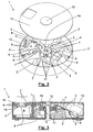
- Figs. 1 to 3 show the first embodiment wherein the support means 3 of the connectors 2 are made by the corresponding arms 7.
- An electrical charging or supply device 1 has a fixed block 9, and the arms 7 are flexibly joined to the displacement means 4a, and can turn with respect to the base 10 of the charging device 1, the arms 7 being radially connected by a joint 11 to the displacement means 4a, so that it is possible to attach a connector 2 to the free end 8 of each of the arms 7.
- the displacement means 4a comprise a turning control 12 accessible from outside the device 1 so that using this, the displacement means 4a are operated.
- Fig. 2 shows the device 1 in resting position A or open connection, showing the cover 13 of the casing and the turning control 12 separated from the rest of the device to aid viewing.
- the terminals 6 of the power supply 5 are free of electrical contact and therefore the device 1 is not operative.
- the block 9 moves one of the arms 7 taking it to operative position B, wherein the connector 2 establishes electrical contact automatically with the power supply 5 through terminals 6 by the elastic devices that force said connection.
- the connector 2 in operative position B is accessible from outside the casing to allow its attachment to the electrical apparatus, whilst the rest of the connectors are housed inside the casing.
- Figs. 4 and 5 show a second embodiment wherein the displacement means 4a or 4b are comprised of a rotating attachment 4b between the terminals 6 support base 10 and the casing.
- the base 10 and the terminals 6 are shown apart from the rest of the device to aid viewing.
- the connectors 2 are placed in coplanar arrangement in the support means 3, soldered to the casing, and at the same distance from the rotation axis of the terminal support base 6.
- the movement of the rotating attachment 4b moves the terminals 6, and the connectors 2 remain static, and passing, as in the first embodiment, from a resting position A, or of open connection, to an operative position B, or closed connection and viceversa.
- Fig. 5 represents the device 1 in the operative position B, wherein the connector 2 establishes electrical contact with the power supply 5, through the terminals 6, so that said connector 2 when connected to the power supply 5 is accessible from outside the casing to allow connection to the electrical apparatus.
- Figs. 1 to 5 shows an attaching system for the connectors' 2 lateral connection and disconnection, to guarantee that they remain in their position when being attached to and removed from the electrical apparatus.
- this invention includes other configurations for said attachments other than those represented.
- Fig. 6 shows a charging device which is not covered by the invention, whose connectors 2 are easily interchangeable because they have an extension 14 that can connect to the support means 3, that in this case are made of a slot 15 made in the cover 13 of the device casing.
- the connectors 2 are fixed and supported by the joint effect of this slot 15 and the cover 13.
- the base 10 wherein they have placed the power supply 5 and various terminals 6 connecting with said power supply 5.
- a configuration of this type, with the connectors 2 fixed to the support means 3, allows to replace or substitute the connectors 2 of one type or sort for connectors 2 of another type or sort according to the model of the electrical apparatus to be connected to the electrical supply. Also, it allows the connectors 2 that should be employed and that are connected to the power supply 5, to be accessible from outside the casing of the device.
- the charging device as schematically shown in Fig. 6 , is a simple device which also allows the simultaneous charging of various electrical apparatus, for example the charging of various mobile telephones.
- the connectors 2 are removable and interchangeable, with such device it can be provided multiple combinations of electrical apparatus at the same time, by substituting the connectors 2 that are not suitable for others that are compatible with the apparatus you wish to charge.
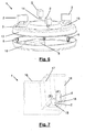
- Fig. 7 represents a third embodiment of the electrical charging or supply device 1 according to the invention.
- This embodiment has an external form that is completely different to those in Figs. 1 to 6 , but has the same characteristics.
- said device 1 has two compartments 16 that are comprised of a base 18 adapted to accommodate the changeable connectors 2, that in the case shown are two but obviously it could be more. It is understood that, inside said base 18 there are all the elements necessary to connect to the electricity supply. You can see that one of the connectors 2 is slightly inclined with respect to the vertical axis of the charging device 1.
Landscapes
- Engineering & Computer Science (AREA)
- Power Engineering (AREA)
- Charge And Discharge Circuits For Batteries Or The Like (AREA)
Abstract
Claims (5)
- Dispositif de chargement ou alimentation électrique (1) pour appareil électrique sans une source d'alimentation permanente, qui comprend une carcasse qui loge divers connecteurs (2) adaptés pour connecter électriquement au moins un appareil électrique à une source d'alimentation (5), lesdits connecteurs (2) pouvant avoir une configuration différente de manière que le dispositif de chargement (1) permet l'accouplement électrique de l'appareil électrique ayant différentes configurations de connexion à l'alimentation électrique; et des moyens de support (3) pour les connecteurs (2), lesdits connecteurs (2) étant accouplés aux moyens de support (3) de manière qu'ils peuvent être retirés et remplacés ou substitués par des connecteurs de différentes configuration par rapport à l'appareil électrique, de telle manière que les connecteurs (2) connectés à la source d'alimentation (5) sont accessible depuis l'extérieur de la carcasse à accoupler à l'appareil électrique, caractérisé en ce qu'il comprend, en outre, des moyens de déplacement (4a, 4b) adaptés pour déplacer lesdits moyens de support (3), et donc les connecteurs, ou les bornes (6) pour la connexion à la source d'alimentation (5), à partir d'une position de repos (A), de connexion ouverte, à une position opérationnelle (B), de connexion fermée, où au moins un connecteur (2) est connecté électriquement à la source d'alimentation (5) à travers les bornes (6) de celle-ci de manière à ce que dans la position opérationnelle (B), les connecteurs (2) connectés à la source d'alimentation (5) sont accessible depuis l'extérieur de la carcasse pour permettre l'accouplement à l'appareil électrique.
- Dispositif de chargement ou alimentation électrique (1) selon la revendication précédente, caractérisé en ce que les moyens de déplacement (4a, 4b) sont constitués par un accouplement rotatif (4a) entre les moyens de support (3) des connecteurs (2) et la carcasse, et en ce que les moyens de support (3), et donc les connecteurs (2), sont unis à l'accouplement rotatif (4a) à des points coplanaires et à la même distance par rapport à l'axe de rotation de ceux-ci.
- Dispositif de chargement ou alimentation électrique (1) selon la revendication 1, caractérisé en ce que les moyens de déplacement (4a, 4b) sont constitués d'un accouplement rotatif (4b) entre une base de support de la borne (6) et la carcasse, et en ce que les connecteurs (2) sont disposés dans une disposition coplanaire sur les moyens de support (3), unis de manière flexible à la carcasse, et à la même distance de l'axe de rotation de la base de support de la borne (6).
- Dispositif de chargement ou alimentation électrique (1) selon les revendications précédentes, caractérisé en ce que dans la position opérationnelle (B), le contact intime entre le connecteur (2) et les bornes (6) de la source d'alimentation est établi automatiquement, par l'action de dispositifs élastiques qui forcent la connexion électrique entre le connecteur (2) et les bornes (6).
- Dispositif de chargement ou alimentation électrique (1) selon l'une quelconque des revendications 1 à 3, caractérisé en ce que dans la position opérationnelle (B), la connexion électrique entre le connecteur (2) et les bornes (6) de la source d'alimentation est établie manuellement, par le biais d'un bouton ou analogue.
Applications Claiming Priority (2)
| Application Number | Priority Date | Filing Date | Title |
|---|---|---|---|
| ES200402047A ES2247937B1 (es) | 2004-08-18 | 2004-08-18 | Dispositivo de carga o suministro electrico. |
| PCT/EP2005/008104 WO2006018103A1 (fr) | 2004-08-18 | 2005-07-26 | Charge electrique ou dispositif d'alimentation |
Publications (2)
| Publication Number | Publication Date |
|---|---|
| EP1787376A1 EP1787376A1 (fr) | 2007-05-23 |
| EP1787376B1 true EP1787376B1 (fr) | 2012-06-27 |
Family
ID=35058422
Family Applications (1)
| Application Number | Title | Priority Date | Filing Date |
|---|---|---|---|
| EP05773139A Expired - Lifetime EP1787376B1 (fr) | 2004-08-18 | 2005-07-26 | Charge electrique ou dispositif d'alimentation |
Country Status (3)
| Country | Link |
|---|---|
| EP (1) | EP1787376B1 (fr) |
| ES (2) | ES2247937B1 (fr) |
| WO (1) | WO2006018103A1 (fr) |
Families Citing this family (2)
| Publication number | Priority date | Publication date | Assignee | Title |
|---|---|---|---|---|
| DE202006010690U1 (de) * | 2006-01-07 | 2007-03-08 | Rosenboom, Volker Wilhelm | Kabellose Ladestation für Mobiltelefone |
| ES2320611B1 (es) * | 2006-11-06 | 2010-01-12 | Inoitulos, S.L. | "dispositivo adaptador para la carga de aparatos electronicos portatiles". |
Family Cites Families (9)
| Publication number | Priority date | Publication date | Assignee | Title |
|---|---|---|---|---|
| US4509450A (en) * | 1982-10-25 | 1985-04-09 | Jondahl Joseph S | Sanitary food dispenser |
| DE4036374A1 (de) * | 1990-11-15 | 1992-05-21 | Bsg Schalttechnik | Ladeeinrichtung fuer wiederaufladbare batterien |
| US5159545A (en) * | 1991-09-09 | 1992-10-27 | Anthony Lee | Universal adapter |
| GB2260040A (en) * | 1991-09-28 | 1993-03-31 | Fu Ching Wang | Battery charger |
| US6064177A (en) * | 1999-01-05 | 2000-05-16 | Dixon; Steven C. | Two-part battery charger/power cable article with multiple device capability |
| US20020115480A1 (en) * | 2001-02-13 | 2002-08-22 | Huang Chih Chen | Adapter set |
| DE10122620A1 (de) * | 2001-05-10 | 2002-11-14 | Kopp Heinrich Ag | Elektrischer Steckadapter |
| TW503929U (en) * | 2001-12-04 | 2002-09-21 | Jonie Chou | Portable power distributor |
| US20030141840A1 (en) * | 2002-01-29 | 2003-07-31 | Grant Sanders | Recharging system for personal electronic devices |
-
2004
- 2004-08-18 ES ES200402047A patent/ES2247937B1/es not_active Expired - Fee Related
-
2005
- 2005-07-26 EP EP05773139A patent/EP1787376B1/fr not_active Expired - Lifetime
- 2005-07-26 WO PCT/EP2005/008104 patent/WO2006018103A1/fr not_active Ceased
- 2005-07-26 ES ES05773139T patent/ES2394024T3/es not_active Expired - Lifetime
Also Published As
| Publication number | Publication date |
|---|---|
| ES2247937A1 (es) | 2006-03-01 |
| ES2394024T3 (es) | 2013-01-15 |
| ES2247937B1 (es) | 2007-04-01 |
| WO2006018103A1 (fr) | 2006-02-23 |
| EP1787376A1 (fr) | 2007-05-23 |
Similar Documents
| Publication | Publication Date | Title |
|---|---|---|
| US5659236A (en) | Battery charger with collapsible battery positioning and support apparatus | |
| US6977479B2 (en) | Portable cell phone battery charger using solar energy as the primary source of power | |
| CN102893483B (zh) | 万能电池充电器 | |
| US6821670B2 (en) | Mobile phone battery | |
| EP2822088A1 (fr) | Batterie de secours et système de charge empilable | |
| PT100840A (pt) | Cartucho para bloco fornecedor de energia electrica ou para alojar pilhas individuais | |
| KR101763754B1 (ko) | 다단 보조배터리 충전 장치 | |
| US10355424B2 (en) | Electronic device holder | |
| US5262710A (en) | Battery charger assembly | |
| US20210204738A1 (en) | Storage box and gimbal assembly having thereof | |
| EP1787376B1 (fr) | Charge electrique ou dispositif d'alimentation | |
| US20080048612A1 (en) | Wireless battery charger | |
| US11398737B2 (en) | Charging station for telecommunication or small electronic devices | |
| CN201100573Y (zh) | 应急灯 | |
| EP4599732A1 (fr) | Ensemble de moyeu de parapluie et bloc-batterie | |
| US8120309B2 (en) | Apparatus and method for charging a first battery from a second battery | |
| CN102157969B (zh) | 一种便携式充电装置 | |
| GB2313242A (en) | Charging portable telephone batteries | |
| US5825158A (en) | Charging device with rotatable power inlet | |
| KR20020086442A (ko) | 영구자석 단자 및 그것을 이용한 2 장치간 전기적 콘택 구조 | |
| CN210273551U (zh) | 一种二合一充电器 | |
| CN220172894U (zh) | 一种组合式充电装置 | |
| CN111564875A (zh) | 多姿态充电器及外壳 | |
| CN220544745U (zh) | 一种组合式无线充电器 | |
| CN217036257U (zh) | 一种充电转接器 |
Legal Events
| Date | Code | Title | Description |
|---|---|---|---|
| PUAI | Public reference made under article 153(3) epc to a published international application that has entered the european phase |
Free format text: ORIGINAL CODE: 0009012 |
|
| 17P | Request for examination filed |
Effective date: 20070228 |
|
| AK | Designated contracting states |
Kind code of ref document: A1 Designated state(s): AT BE BG CH CY CZ DE DK EE ES FI FR GB GR HU IE IS IT LI LT LU LV MC NL PL PT RO SE SI SK TR |
|
| DAX | Request for extension of the european patent (deleted) | ||
| 17Q | First examination report despatched |
Effective date: 20080204 |
|
| GRAP | Despatch of communication of intention to grant a patent |
Free format text: ORIGINAL CODE: EPIDOSNIGR1 |
|
| GRAS | Grant fee paid |
Free format text: ORIGINAL CODE: EPIDOSNIGR3 |
|
| GRAA | (expected) grant |
Free format text: ORIGINAL CODE: 0009210 |
|
| AK | Designated contracting states |
Kind code of ref document: B1 Designated state(s): AT BE BG CH CY CZ DE DK EE ES FI FR GB GR HU IE IS IT LI LT LU LV MC NL PL PT RO SE SI SK TR |
|
| REG | Reference to a national code |
Ref country code: GB Ref legal event code: FG4D |
|
| REG | Reference to a national code |
Ref country code: CH Ref legal event code: EP |
|
| REG | Reference to a national code |
Ref country code: AT Ref legal event code: REF Ref document number: 564632 Country of ref document: AT Kind code of ref document: T Effective date: 20120715 |
|
| REG | Reference to a national code |
Ref country code: IE Ref legal event code: FG4D |
|
| REG | Reference to a national code |
Ref country code: DE Ref legal event code: R096 Ref document number: 602005034954 Country of ref document: DE Effective date: 20120816 |
|
| PG25 | Lapsed in a contracting state [announced via postgrant information from national office to epo] |
Ref country code: SE Free format text: LAPSE BECAUSE OF FAILURE TO SUBMIT A TRANSLATION OF THE DESCRIPTION OR TO PAY THE FEE WITHIN THE PRESCRIBED TIME-LIMIT Effective date: 20120627 Ref country code: LT Free format text: LAPSE BECAUSE OF FAILURE TO SUBMIT A TRANSLATION OF THE DESCRIPTION OR TO PAY THE FEE WITHIN THE PRESCRIBED TIME-LIMIT Effective date: 20120627 Ref country code: FI Free format text: LAPSE BECAUSE OF FAILURE TO SUBMIT A TRANSLATION OF THE DESCRIPTION OR TO PAY THE FEE WITHIN THE PRESCRIBED TIME-LIMIT Effective date: 20120627 |
|
| REG | Reference to a national code |
Ref country code: NL Ref legal event code: VDEP Effective date: 20120627 |
|
| REG | Reference to a national code |
Ref country code: AT Ref legal event code: MK05 Ref document number: 564632 Country of ref document: AT Kind code of ref document: T Effective date: 20120627 |
|
| REG | Reference to a national code |
Ref country code: LT Ref legal event code: MG4D Effective date: 20120627 |
|
| PG25 | Lapsed in a contracting state [announced via postgrant information from national office to epo] |
Ref country code: GR Free format text: LAPSE BECAUSE OF FAILURE TO SUBMIT A TRANSLATION OF THE DESCRIPTION OR TO PAY THE FEE WITHIN THE PRESCRIBED TIME-LIMIT Effective date: 20120928 Ref country code: SI Free format text: LAPSE BECAUSE OF FAILURE TO SUBMIT A TRANSLATION OF THE DESCRIPTION OR TO PAY THE FEE WITHIN THE PRESCRIBED TIME-LIMIT Effective date: 20120627 Ref country code: LV Free format text: LAPSE BECAUSE OF FAILURE TO SUBMIT A TRANSLATION OF THE DESCRIPTION OR TO PAY THE FEE WITHIN THE PRESCRIBED TIME-LIMIT Effective date: 20120627 |
|
| REG | Reference to a national code |
Ref country code: ES Ref legal event code: FG2A Ref document number: 2394024 Country of ref document: ES Kind code of ref document: T3 Effective date: 20130115 |
|
| RAP2 | Party data changed (patent owner data changed or rights of a patent transferred) |
Owner name: INOITULOS, S.L. |
|
| RIN2 | Information on inventor provided after grant (corrected) |
Inventor name: GIRIBET GUADAMILLAS, JACQUES |
|
| PG25 | Lapsed in a contracting state [announced via postgrant information from national office to epo] |
Ref country code: SK Free format text: LAPSE BECAUSE OF FAILURE TO SUBMIT A TRANSLATION OF THE DESCRIPTION OR TO PAY THE FEE WITHIN THE PRESCRIBED TIME-LIMIT Effective date: 20120627 Ref country code: CZ Free format text: LAPSE BECAUSE OF FAILURE TO SUBMIT A TRANSLATION OF THE DESCRIPTION OR TO PAY THE FEE WITHIN THE PRESCRIBED TIME-LIMIT Effective date: 20120627 Ref country code: CY Free format text: LAPSE BECAUSE OF FAILURE TO SUBMIT A TRANSLATION OF THE DESCRIPTION OR TO PAY THE FEE WITHIN THE PRESCRIBED TIME-LIMIT Effective date: 20120627 Ref country code: IS Free format text: LAPSE BECAUSE OF FAILURE TO SUBMIT A TRANSLATION OF THE DESCRIPTION OR TO PAY THE FEE WITHIN THE PRESCRIBED TIME-LIMIT Effective date: 20121027 Ref country code: RO Free format text: LAPSE BECAUSE OF FAILURE TO SUBMIT A TRANSLATION OF THE DESCRIPTION OR TO PAY THE FEE WITHIN THE PRESCRIBED TIME-LIMIT Effective date: 20120627 Ref country code: EE Free format text: LAPSE BECAUSE OF FAILURE TO SUBMIT A TRANSLATION OF THE DESCRIPTION OR TO PAY THE FEE WITHIN THE PRESCRIBED TIME-LIMIT Effective date: 20120627 Ref country code: BE Free format text: LAPSE BECAUSE OF FAILURE TO SUBMIT A TRANSLATION OF THE DESCRIPTION OR TO PAY THE FEE WITHIN THE PRESCRIBED TIME-LIMIT Effective date: 20120627 Ref country code: AT Free format text: LAPSE BECAUSE OF FAILURE TO SUBMIT A TRANSLATION OF THE DESCRIPTION OR TO PAY THE FEE WITHIN THE PRESCRIBED TIME-LIMIT Effective date: 20120627 |
|
| PG25 | Lapsed in a contracting state [announced via postgrant information from national office to epo] |
Ref country code: MC Free format text: LAPSE BECAUSE OF NON-PAYMENT OF DUE FEES Effective date: 20120731 Ref country code: PT Free format text: LAPSE BECAUSE OF FAILURE TO SUBMIT A TRANSLATION OF THE DESCRIPTION OR TO PAY THE FEE WITHIN THE PRESCRIBED TIME-LIMIT Effective date: 20121029 Ref country code: PL Free format text: LAPSE BECAUSE OF FAILURE TO SUBMIT A TRANSLATION OF THE DESCRIPTION OR TO PAY THE FEE WITHIN THE PRESCRIBED TIME-LIMIT Effective date: 20120627 |
|
| REG | Reference to a national code |
Ref country code: CH Ref legal event code: PL |
|
| PG25 | Lapsed in a contracting state [announced via postgrant information from national office to epo] |
Ref country code: NL Free format text: LAPSE BECAUSE OF FAILURE TO SUBMIT A TRANSLATION OF THE DESCRIPTION OR TO PAY THE FEE WITHIN THE PRESCRIBED TIME-LIMIT Effective date: 20120627 |
|
| PG25 | Lapsed in a contracting state [announced via postgrant information from national office to epo] |
Ref country code: CH Free format text: LAPSE BECAUSE OF NON-PAYMENT OF DUE FEES Effective date: 20120731 Ref country code: DK Free format text: LAPSE BECAUSE OF FAILURE TO SUBMIT A TRANSLATION OF THE DESCRIPTION OR TO PAY THE FEE WITHIN THE PRESCRIBED TIME-LIMIT Effective date: 20120627 Ref country code: LI Free format text: LAPSE BECAUSE OF NON-PAYMENT OF DUE FEES Effective date: 20120731 |
|
| PLBE | No opposition filed within time limit |
Free format text: ORIGINAL CODE: 0009261 |
|
| STAA | Information on the status of an ep patent application or granted ep patent |
Free format text: STATUS: NO OPPOSITION FILED WITHIN TIME LIMIT |
|
| REG | Reference to a national code |
Ref country code: IE Ref legal event code: MM4A |
|
| 26N | No opposition filed |
Effective date: 20130328 |
|
| REG | Reference to a national code |
Ref country code: DE Ref legal event code: R097 Ref document number: 602005034954 Country of ref document: DE Effective date: 20130328 |
|
| PG25 | Lapsed in a contracting state [announced via postgrant information from national office to epo] |
Ref country code: IE Free format text: LAPSE BECAUSE OF NON-PAYMENT OF DUE FEES Effective date: 20120726 Ref country code: BG Free format text: LAPSE BECAUSE OF FAILURE TO SUBMIT A TRANSLATION OF THE DESCRIPTION OR TO PAY THE FEE WITHIN THE PRESCRIBED TIME-LIMIT Effective date: 20120927 |
|
| PGFP | Annual fee paid to national office [announced via postgrant information from national office to epo] |
Ref country code: DE Payment date: 20130722 Year of fee payment: 9 Ref country code: ES Payment date: 20130717 Year of fee payment: 9 |
|
| PGFP | Annual fee paid to national office [announced via postgrant information from national office to epo] |
Ref country code: FR Payment date: 20130729 Year of fee payment: 9 Ref country code: GB Payment date: 20130716 Year of fee payment: 9 |
|
| PGFP | Annual fee paid to national office [announced via postgrant information from national office to epo] |
Ref country code: IT Payment date: 20130716 Year of fee payment: 9 |
|
| PG25 | Lapsed in a contracting state [announced via postgrant information from national office to epo] |
Ref country code: TR Free format text: LAPSE BECAUSE OF FAILURE TO SUBMIT A TRANSLATION OF THE DESCRIPTION OR TO PAY THE FEE WITHIN THE PRESCRIBED TIME-LIMIT Effective date: 20120627 |
|
| PG25 | Lapsed in a contracting state [announced via postgrant information from national office to epo] |
Ref country code: LU Free format text: LAPSE BECAUSE OF NON-PAYMENT OF DUE FEES Effective date: 20120726 |
|
| PG25 | Lapsed in a contracting state [announced via postgrant information from national office to epo] |
Ref country code: HU Free format text: LAPSE BECAUSE OF FAILURE TO SUBMIT A TRANSLATION OF THE DESCRIPTION OR TO PAY THE FEE WITHIN THE PRESCRIBED TIME-LIMIT Effective date: 20050726 |
|
| REG | Reference to a national code |
Ref country code: DE Ref legal event code: R119 Ref document number: 602005034954 Country of ref document: DE |
|
| GBPC | Gb: european patent ceased through non-payment of renewal fee |
Effective date: 20140726 |
|
| REG | Reference to a national code |
Ref country code: FR Ref legal event code: ST Effective date: 20150331 |
|
| PG25 | Lapsed in a contracting state [announced via postgrant information from national office to epo] |
Ref country code: DE Free format text: LAPSE BECAUSE OF NON-PAYMENT OF DUE FEES Effective date: 20150203 Ref country code: IT Free format text: LAPSE BECAUSE OF NON-PAYMENT OF DUE FEES Effective date: 20140726 |
|
| REG | Reference to a national code |
Ref country code: DE Ref legal event code: R119 Ref document number: 602005034954 Country of ref document: DE Effective date: 20150203 |
|
| PG25 | Lapsed in a contracting state [announced via postgrant information from national office to epo] |
Ref country code: GB Free format text: LAPSE BECAUSE OF NON-PAYMENT OF DUE FEES Effective date: 20140726 Ref country code: FR Free format text: LAPSE BECAUSE OF NON-PAYMENT OF DUE FEES Effective date: 20140731 |
|
| REG | Reference to a national code |
Ref country code: ES Ref legal event code: FD2A Effective date: 20150827 |
|
| PG25 | Lapsed in a contracting state [announced via postgrant information from national office to epo] |
Ref country code: ES Free format text: LAPSE BECAUSE OF NON-PAYMENT OF DUE FEES Effective date: 20140727 |