EP1787384B1 - Procede et appareil de commande de generateur - Google Patents
Procede et appareil de commande de generateur Download PDFInfo
- Publication number
- EP1787384B1 EP1787384B1 EP05795300A EP05795300A EP1787384B1 EP 1787384 B1 EP1787384 B1 EP 1787384B1 EP 05795300 A EP05795300 A EP 05795300A EP 05795300 A EP05795300 A EP 05795300A EP 1787384 B1 EP1787384 B1 EP 1787384B1
- Authority
- EP
- European Patent Office
- Prior art keywords
- generator
- circuit
- level
- line
- output
- Prior art date
- Legal status (The legal status is an assumption and is not a legal conclusion. Google has not performed a legal analysis and makes no representation as to the accuracy of the status listed.)
- Expired - Lifetime
Links
Images


Classifications
-
- H—ELECTRICITY
- H02—GENERATION; CONVERSION OR DISTRIBUTION OF ELECTRIC POWER
- H02P—CONTROL OR REGULATION OF ELECTRIC MOTORS, ELECTRIC GENERATORS OR DYNAMO-ELECTRIC CONVERTERS; CONTROLLING TRANSFORMERS, REACTORS OR CHOKE COILS
- H02P9/00—Arrangements for controlling electric generators for the purpose of obtaining a desired output
- H02P9/14—Arrangements for controlling electric generators for the purpose of obtaining a desired output by variation of field
- H02P9/26—Arrangements for controlling electric generators for the purpose of obtaining a desired output by variation of field using discharge tubes or semiconductor devices
- H02P9/30—Arrangements for controlling electric generators for the purpose of obtaining a desired output by variation of field using discharge tubes or semiconductor devices using semiconductor devices
-
- H—ELECTRICITY
- H02—GENERATION; CONVERSION OR DISTRIBUTION OF ELECTRIC POWER
- H02P—CONTROL OR REGULATION OF ELECTRIC MOTORS, ELECTRIC GENERATORS OR DYNAMO-ELECTRIC CONVERTERS; CONTROLLING TRANSFORMERS, REACTORS OR CHOKE COILS
- H02P27/00—Arrangements or methods for the control of AC motors characterised by the kind of supply voltage
- H02P27/04—Arrangements or methods for the control of AC motors characterised by the kind of supply voltage using variable-frequency supply voltage, e.g. inverter or converter supply voltage
- H02P27/06—Arrangements or methods for the control of AC motors characterised by the kind of supply voltage using variable-frequency supply voltage, e.g. inverter or converter supply voltage using DC to AC converters or inverters
-
- H—ELECTRICITY
- H02—GENERATION; CONVERSION OR DISTRIBUTION OF ELECTRIC POWER
- H02P—CONTROL OR REGULATION OF ELECTRIC MOTORS, ELECTRIC GENERATORS OR DYNAMO-ELECTRIC CONVERTERS; CONTROLLING TRANSFORMERS, REACTORS OR CHOKE COILS
- H02P2101/00—Special adaptation of control arrangements for generators
- H02P2101/30—Special adaptation of control arrangements for generators for aircraft
Definitions
- the present application is directed to a method and apparatus for controlling a generator, and more specifically, toward a method and apparatus for decreasing the power supplied to a generator when current flowing through a generator field winding ceases to be controlled.
- Both AC and DC generators may be controlled by regulating the current flowing through a generator field winding. This current is generally supplied though a controlled transistor, frequently a MOSFET. By controlling the field transistor, the generator field current is modulated based on demand to maintain the generator output voltage at a desired level.
- One failure mode for a generator may be referred to as an "out of control" failure mode.
- a generator control unit fails to control the generator excitation current, and the generator output voltage quickly reaches dangerously high levels. This may damage equipment connected to the generator.
- the cause of this failure mode may be, for example, a shorted field transistor, or a short of any components that are connected in parallel with the field transistor, or a connector pin short. Because the field switch is a semiconductor device, this is not an uncommon failure mode.
- variable frequency electrical systems such as those sometimes found on aircraft.
- variable frequency electrical systems are becoming increasingly popular because of their overall lighter weight and increased efficiency.
- the generator may operate at frequencies nearly twice as high as the frequencies used in constant frequency systems.
- Some systems now require generators that limit overvoltage to about 150 V rms for 115V AC electrical systems and to 300V rms for 230V AC electrical systems.
- a conventional approach to overvoltage protection is to monitor voltage levels and disconnect the field winding when an overvoltage is detected. This approach, however, is too slow to provide effective protection for the above failure mode, especially in a variable frequency system.
- UA-5262711 discloses a charging generator for a vehicle including a circuit for suppressing a sudden change in a field current.
- Figures 4a and 4b illustrate a simulated response to an overvoltage condition by a conventional voltage protection circuit used with a generator operating at 115V, 700 Hz with a light load of 7.5 kW.
- Figure 4a is a graph of generator field current having a nominal level of 0.4 amps.
- Figure 4b illustrates the average voltage level of the three-phase power supply. A fault occurs at time t1 which leads to an increase in the current level to about 3.2 amps at time t2.
- the generator field voltage peaks at 248.5 V or 176 V rms, well above the 150V rms limit often required in applications employing variable frequency generators. It is therefore desirable to provide a method and apparatus for addressing this failure mode in a manner that limits generator overvoltage and protects components connected to the generator.
- a generator control circuit that includes a first circuit monitoring a generator voltage change rate and producing a first output when the voltage change rate is above a first level and a second circuit monitoring a generator current change rate and producing a second output when the current change rate is above a second level. These circuits are connected to a third circuit which decreases the power supplied to the generator when a plurality of conditions are satisfied, the plurality of conditions including the voltage change rate being above the first level and the current change rate being above the second level.
- Another aspect of the invention comprises a method of protecting a generator that involves monitoring a rate of generator voltage change, monitoring a rate of generator current change, and reducing a power supplied to the generator when a plurality of conditions are satisfied.
- the plurality of conditions include the rate of generator voltage change exceeding a first level and the rate of generator current change exceeding a second level
- Figure 1 illustrates a control circuit for a generator (not shown) having an exciter winding 10 connected to a power supply 12 controlled by a switch 13, (preferably a semiconductor switch) by a line 14 and to ground via a field transistor 16.
- the conductive state of field transistor 16 which is may be, for example, a MOSFET, is regulated by pulse width modulation (PWM) controller 18 via PWM gating 20 to control the output of a generator in a well known manner.
- PWM pulse width modulation
- a field dumping line 22 connects to a node 24 between exciter winding 10 and field transistor 16.
- Field dumping control 28 controls transistor 30 to determine a current flow path from node 24 to freewheeling diode 26.
- transistor 30 When transistor 30 is conducting, current flows through transistor 30 to the freewheeling diode 26, bypassing resistor 32.
- transistor 30 is not conducting, current flows through and is dissipated by resistor 32.
- the state of power supply switch 13 and field dumping control 28 is determined by the logical state of node 34 on line 36.
- the signal on line 36 is normally low when the generator is operating in a normal manner.
- the signal goes high, as described hereinafter, upon the detection of a fault indicative of a failure or bypass of field transistor 16, and this turns off or reduces the output of power supply 12.
- the monitoring circuits include a generator output voltage detection circuit 40 providing an output on voltage detection output line 42, a dv/dt monitoring circuit 44 producing an output on dv/dt output line 46, a di/dt monitoring circuit 48 producing an output signal on di/dt output line 50 and a generator line contactor (GLC) monitoring circuit 52 producing an output on GLC line 54.
- GLC generator line contactor
- dv/dt monitoring circuit 44 and di/dt monitoring circuit 48 sense for rapid changes in both voltage and current levels. Normal system operation may occasionally produce an increase in one or the other of these values, but concurrent increases are generally associated with a fault condition. Because the rate of current and voltage change is sensed rather than the absolute value of these quantities, faults can be detected and corrective action taken before the generator output reaches a dangerous level.
- the present inventor has also recognized that under certain transient conditions, dv/dt or di/dt or both may increase when a fault is not present. This may occur, for example, at generator power up and/or when a load is applied to the generator. To prevent those conditions from triggering a fault protection sequence, two additional logically high inputs to AND gate 38 are required before the fault protection system is triggered.
- output voltage detection circuit 40 monitors the generator output voltage and outputs a logically high signal on voltage detection output line 42 only when the voltage is above a nominal level, such as 5 volts, for example, to prevent the signaling of a fault condition on start up before output voltage has reached a stable level.
- GLC monitoring circuit 52 produces a high output on GLC output line 54 only when the GLC is closed to prevent the triggering of a failure mode when the GLC is open.
- AND gate 38 produces a logically high signal on line 36, which signal is latched to a high level by latch 56, and triggers a shutdown of the generator.
- output voltage detection circuit 44 comprises a first operational amplifier 60 connected to +12V and -12V power supplies and having a first line 62 connected to the output of a generator (not shown) at the point of regulation (POR) and to the inverting input of first op amp 60 through a first resistor R1, and a second line 64 connected to the output of the generator and the non-inverting input of op amp 60 through a second resistor R2 where first and second resistors R1 and R2 each have a resistance of, for example, 75 k ⁇ .
- a third line 66 provides feedback from the output of the first op amp 60 to the inverting input thereof through a third resistor R3 (1.43 k ⁇ ), while second line 64 is connected to ground thorough a fourth resistor R4 (1.43 k ⁇ ).
- the output of first op amp 60 on fourth line 68 is conditioned by first logic conditioning circuit 70 which outputs a specific signal, assumed to be logically high for this example, on line 42 when the generator output voltage on first line 62 and on second line 64 is at least 5V.
- the dv/dt detection circuit 44 receives as an input the output voltage of first op amp 60 on a fifth line 72 connected to the inverting input of a second op amp 74.
- Fifth line 72 includes a fifth resistor R5 (10 k ⁇ ) and is connected to ground at a point between fifth resistor R5 and first op amp 60 via a sixth resistor R6 (2M ⁇ ) and a first capacitor C1 (0.22 ⁇ F) arranged in parallel.
- First capacitor C1 filters the incoming signal, and its value is chosen so that normal noise on fifth line 72 does not trigger dv/dt detection circuit 44.
- Fifth line 72 further includes a second capacitor C2 ( 0.01 ⁇ F) and a seventh resistor R7 (50 k ⁇ ) between fifth resistor R5 and the inverting input of second op amp 74.
- the value of second capacitor C2 determines the sensitivity of the dv/dt detector.
- the non-inverting input of second op amp 74 is connected to a 12V power source by a sixth line 76 through an eighth resistor R8, and sixth line 76 is connected to ground through a tenth resistor R10 (100 k ⁇ ).
- Seventh line 78 provides feedback from the output of second op amp 74 to the inverting input of second op amp 74 through a ninth resistor R9 (150 k ⁇ ), and the output of second op amp 74 on eighth line 80, which is proportional to the derivative of the voltage on first line 62, is conditioned by second logic conditioning circuit 82 to produce a logically high output on dv/dt output line 46 when a voltage change is detected.
- the di/dt monitoring circuit 48 receives a current input on ninth line 84, which current is normally the generator field winding current. However, in systems where some minimum load is always connected to the generator, the load current can be monitored instead.
- Ninth line 84 is connected to the inverting input of a third op amp 86.
- Ninth line 84 includes an eleventh resistor R11 (12 k ⁇ ) and is connected to ground at a point between eleventh resistor R11 and third op amp 86 via a twelfth resistor R12 (2M ⁇ ) and a third capacitor C3 (0.22 ⁇ F) arranged in parallel.
- Third capacitor C3 filters the incoming signal, and its value is chosen so that normal noise on ninth line 84 does not trigger di/dt detection circuit 48.
- Ninth line 84 further includes a fourth capacitor C4 ( 0.01 ⁇ F) and thirteenth resistor R13 (50 k ⁇ ) between eleventh resistor R11 and the inverting input of third op amp 86.
- the value of third capacitor C3 determines the sensitivity of the di/dt detector.
- the non-inverting input of third op amp 86 is connected to a 12V power source by a tenth line 88 through a fourteenth resistor R14, and tenth line 88 is connected to ground through a sixteenth resistor R16 (100 k ⁇ ).
- Eleventh line 90 provides feedback from the output of third op amp 86 to the inverting input of third op amp 86 through a fifteenth resistor R15 (150 k ⁇ ), and the output of third op amp 86 on twelfth line 92, which is proportional to the derivative of the current on ninth line 84, is conditioned by third logic conditioning circuit 94 which produces a logically high output on di/dt output line 50 when a current change of a given magnitude is detected.
- GLC monitoring circuit 52 provides a logically high output on line 54 when the generator line contactor is closed.
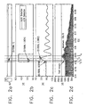
- FIGs 2a - 2d illustrate voltage and current levels during a simulated generator out of control fault and show how such a fault is handled by the protective circuitry of one embodiment of the present invention.
- generator field current begins to increase at time t1 which produces a positive di/dt as illustrated by the dotted line in Figure 2b .
- This positive di/dt is detected by di/dt monitoring circuit 48 and causes the signal on di/dt output line 46 to go high.
- time t2 about 0.1 msec after the fault occurs, an increase in generator output voltage is seen, and this voltage change is detected as illustrated by the solid line in Figure 2b which causes the output of dv/dt monitoring circuit 44 to go high at time t2.
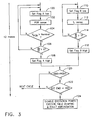
- Figure 3 illustrates the logical steps followed by the fault protection system of an embodiment of the present invention.
- a first flag A is set to low and the generator output voltage is sensed at step 102.
- a determination is made at step 104 as to whether the sensed generator output voltage is greater than a predetermined nominal level such as 5 V, for example. If the sensed voltage is not greater than this nominal level, the process returns to step 100. If the sensed voltage is greater than the nominal level, a determination is made at a step 106 as to whether the voltage level is changing more quickly than a certain rate. If the voltage level is not changing at such a rate, the process returns to step 100. If the voltage is changing at a rate greater than a predetermined rate, flag A is set to high at step 108.
- steps 110 through 116 are performed.
- a flag B is set to low and a current level is sensed at a step 112.
- a determination is made at step 114 as to whether the current is changing more quickly than a certain rate. If such a current rate change is not detected, the process returns to step 110. If the current is changing more quickly than this rate, flag B is set to high at step 116.
Landscapes
- Engineering & Computer Science (AREA)
- Power Engineering (AREA)
- Control Of Eletrric Generators (AREA)
Abstract
Claims (7)
- Circuit de commande d'un générateur, comprenant :un premier circuit (44) surveillant un taux de variation de tension du générateur et produisant une première sortie si le taux de variation de tension est supérieur à un premier niveau ;caractérisé par :un deuxième circuit (48) surveillant un taux de variation de courant du générateur et produisant une deuxième sortie si le taux de variation de courant est supérieur à un deuxième niveau ; etun troisième circuit (13, 28), relié de façon fonctionnelle audit premier circuit (44) et audit deuxième circuit (48), destiné à réduire un niveau de puissance appliqué au générateur si une pluralité de conditions sont satisfaites, ladite pluralité de conditions comprenant le fait que ledit taux de variation de tension est supérieur au premier niveau et le fait que ledit taux de variation de courant est supérieur au deuxième niveau.
- Circuit de commande d'un générateur selon la revendication 1, le fait que ledit générateur se trouve dans un mode de fonctionnement normal constituant une de ladite pluralité de conditions.
- Circuit de commande d'un générateur selon la revendication 1, comportant un quatrième circuit (40) surveillant une tension de sortie du générateur, et le fait que ladite tension de sortie du générateur est supérieure à un niveau prédéfini constituant une de ladite pluralité de conditions.
- Circuit de commande d'un générateur selon la revendication 1, le fait qu'un contacteur de ligne du générateur est fermé constituant une de ladite pluralité de conditions.
- Procédé de protection d'un générateur, comprenant l'étape consistant à :surveiller un taux de variation de tension du générateur ; etcaractérisé en ce qu'il comprend en outre les étapes consistant à :surveiller un taux de variation de courant du générateur ; etréduire un niveau de puissance appliqué au générateur si une pluralité de conditions sont satisfaites, la pluralité de conditions comprenant le fait que le taux de variation de tension est supérieur à un premier niveau et le fait que le taux de variation de courant est supérieur à un deuxième niveau.
- Procédé selon la revendication 5, le fait que le générateur se trouve dans un mode de fonctionnement normal constituant une de la pluralité de conditions.
- Procédé selon la revendication 5, le fait qu'un contacteur de ligne du générateur est fermé constituant une de la pluralité de conditions.
Applications Claiming Priority (2)
| Application Number | Priority Date | Filing Date | Title |
|---|---|---|---|
| US10/936,399 US7196498B2 (en) | 2004-09-08 | 2004-09-08 | Method and apparatus for generator control |
| PCT/US2005/032245 WO2006029360A1 (fr) | 2004-09-08 | 2005-09-08 | Procede et appareil de commande de generateur |
Publications (2)
| Publication Number | Publication Date |
|---|---|
| EP1787384A1 EP1787384A1 (fr) | 2007-05-23 |
| EP1787384B1 true EP1787384B1 (fr) | 2010-11-24 |
Family
ID=35515657
Family Applications (1)
| Application Number | Title | Priority Date | Filing Date |
|---|---|---|---|
| EP05795300A Expired - Lifetime EP1787384B1 (fr) | 2004-09-08 | 2005-09-08 | Procede et appareil de commande de generateur |
Country Status (4)
| Country | Link |
|---|---|
| US (2) | US7196498B2 (fr) |
| EP (1) | EP1787384B1 (fr) |
| DE (1) | DE602005024986D1 (fr) |
| WO (1) | WO2006029360A1 (fr) |
Families Citing this family (20)
| Publication number | Priority date | Publication date | Assignee | Title |
|---|---|---|---|---|
| US7196498B2 (en) * | 2004-09-08 | 2007-03-27 | Honeywell International Inc. | Method and apparatus for generator control |
| FR2912848B1 (fr) | 2007-02-20 | 2010-09-17 | Commissariat Energie Atomique | Limiteur de tension et protection d'un module photovoltaique |
| US7633272B2 (en) * | 2007-07-11 | 2009-12-15 | Honeywell International Inc. | Load-off transient acceleration generator control system |
| US8134344B2 (en) * | 2008-07-15 | 2012-03-13 | Honeywell International, Inc. | Regulation control for variable frequency generators |
| JPWO2011055449A1 (ja) * | 2009-11-06 | 2013-03-21 | 三菱電機株式会社 | 車両用発電電圧制御装置 |
| FR2977677B1 (fr) | 2011-07-04 | 2013-08-23 | Commissariat Energie Atomique | Detection d'arcs electriques dans les installations photovoltaiques |
| US9130562B2 (en) * | 2013-03-13 | 2015-09-08 | Alpha And Omega Semiconductor Incorporated | Active ESD protection circuit |
| US8836293B1 (en) | 2013-03-15 | 2014-09-16 | Hamilton Sundstrand Corporation | Variable speed constant frequency system with generator and rotating power converter |
| US9257889B2 (en) | 2013-03-15 | 2016-02-09 | Hamilton Sundstrand Corporation | EPGS architecture with multi-channel synchronous generator and common field regulated exciter |
| US8912765B2 (en) * | 2013-03-15 | 2014-12-16 | Hamilton Sundstrand Corporation | EPGS architecture with multi-channel synchronous generator and common unregulated PMG exciter |
| US9325229B2 (en) | 2013-03-15 | 2016-04-26 | Hamilton Sundstrand Corporation | Generator architecture with PMG exciter and main field rotating power converter |
| US8975876B2 (en) | 2013-03-15 | 2015-03-10 | Hamilton Sunstrand Corporation | Method of controlling rotating main field converter |
| US9054610B2 (en) | 2013-03-15 | 2015-06-09 | United Technologies Corporation | Generator architecture with main field rotating power converter |
| FR3010260B1 (fr) | 2013-08-29 | 2015-10-02 | Commissariat Energie Atomique | Detection d'arcs electriques dans les installations photovoltaiques |
| FR3010261B1 (fr) | 2013-08-29 | 2015-10-02 | Commissariat Energie Atomique | Detection d'un arc electrique en parallele sur les bornes principales d'une installation photovoltaique |
| GB201315497D0 (en) * | 2013-08-30 | 2013-10-16 | Microgen Engine Corp Holding Bv | Regulation of electrical generator output |
| US10707788B2 (en) * | 2015-07-28 | 2020-07-07 | Ford Global Technologies, Llc | Vehicle transient voltage control |
| US10727671B2 (en) * | 2017-08-08 | 2020-07-28 | Solar Turbines Incorporated | Gas turbine electrical power system and control strategy for limiting reverse power shutdown |
| US11699966B1 (en) | 2022-02-11 | 2023-07-11 | Hamilton Sundstrand Corporation | Open flyback diode protection |
| US20250211004A1 (en) * | 2023-12-21 | 2025-06-26 | Advanced Energy Industries, Inc. | Open circuit and back-surge protection for power supplies |
Family Cites Families (30)
| Publication number | Priority date | Publication date | Assignee | Title |
|---|---|---|---|---|
| US3656048A (en) * | 1970-07-16 | 1972-04-11 | Us Interior | Non-linear exciter controller for power system damping |
| DE2221877A1 (de) * | 1972-05-04 | 1973-11-15 | Siemens Ag | Anordnung zur spannungsregelung von synchronmaschinen |
| US3996507A (en) * | 1975-08-27 | 1976-12-07 | General Electric Company | Regulator for controlling synchronous dynamoelectric machines |
| US4044296A (en) * | 1976-01-14 | 1977-08-23 | Sundstrand Corporation | Electronic voltage regulator for three-phase generators |
| DE2622309C3 (de) * | 1976-05-19 | 1979-05-03 | Siemens Ag, 1000 Berlin Und 8000 Muenchen | Schutzeinrichtung für eine bürstenlose Synchronmaschine |
| DE3625211A1 (de) * | 1986-07-25 | 1988-02-04 | Bosch Gmbh Robert | Spannungsregler fuer einen generator |
| US4777425A (en) * | 1986-08-15 | 1988-10-11 | Marathon Electric Manufacturing Corp. | Alternator voltage regulator with speed responsive control |
| US5166538A (en) * | 1986-12-15 | 1992-11-24 | Peter Norton | Dual or single voltage vehicular power supply with improved switch driver and load dump |
| US5168208A (en) * | 1988-05-09 | 1992-12-01 | Onan Corporation | Microprocessor based integrated generator set controller apparatus and method |
| US4807106A (en) * | 1988-05-12 | 1989-02-21 | Westinghouse Electric Corp. | Method and circuit for voltage regulation of DC power sources |
| CA2005093A1 (fr) * | 1988-12-29 | 1990-06-29 | David A. Fox | Circuit de regulation de tension des sources d'alimentation en electricite, et methode connexe |
| US4924170A (en) * | 1989-01-03 | 1990-05-08 | Unisys Corporation | Current sharing modular power supply |
| IT1237696B (it) * | 1989-12-18 | 1993-06-15 | Fiat Auto Spa | Dispositivo di misura del numero di giri dell'albero di un motore elettrico a magneti permanenti. |
| JPH0412639A (ja) * | 1990-04-27 | 1992-01-17 | Hitachi Ltd | 車両用充電発電機 |
| US5055765A (en) * | 1990-09-04 | 1991-10-08 | Sundstrand Corporation | Voltage regulator for direct current aircraft power bus |
| FI89415C (fi) * | 1992-01-09 | 1993-09-27 | Abb Stroemberg Drives Oy | Foerfarande foer att bestaemma kortslutningsinduktansen i en asynkronmaskin |
| US5412251A (en) * | 1993-01-14 | 1995-05-02 | Toyota Jidosha Kabushiki Kaisha | Controller of an engine driving generator for an electric vehicle |
| US5583420A (en) * | 1993-10-01 | 1996-12-10 | Lucas Aerospace Power Equipment Corporation | Microprocessor controller for starter/generator |
| JP3102981B2 (ja) * | 1993-12-28 | 2000-10-23 | 三菱電機株式会社 | 車両用交流発電機の出力制御装置 |
| US5886504A (en) * | 1994-09-14 | 1999-03-23 | Coleman Powermate, Inc. | Throttle controlled generator system |
| US5754033A (en) * | 1996-03-13 | 1998-05-19 | Alaska Power Systems Inc. | Control system and circuits for distributed electrical-power generating stations |
| US6201382B1 (en) * | 1996-10-08 | 2001-03-13 | Matsushita Electric Industrial Co., Ltd. | Low noise and energy loss power supply apparatus and voltage converter |
| US6166525A (en) * | 1998-01-26 | 2000-12-26 | Crook; Gaines M. | Automatic electric power generator control |
| JP2000050696A (ja) * | 1998-08-03 | 2000-02-18 | Sawafuji Electric Co Ltd | 発動発電機用自動電圧調整装置 |
| US6097178A (en) * | 1998-09-14 | 2000-08-01 | Linear Technology Corporation | Circuits and methods for multiple-input, single-output, low-dropout voltage regulators |
| US6975494B2 (en) * | 2001-01-29 | 2005-12-13 | Primarion, Inc. | Method and apparatus for providing wideband power regulation to a microelectronic device |
| TW595077B (en) * | 2002-04-03 | 2004-06-21 | Int Rectifier Corp | Synchronous buck converter improvements |
| US6801027B2 (en) * | 2002-09-26 | 2004-10-05 | Itt Manufacturing Enterprises, Inc. | Power conversion in variable load applications |
| US6801028B2 (en) * | 2002-11-14 | 2004-10-05 | Fyre Storm, Inc. | Phase locked looped based digital pulse converter |
| US7196498B2 (en) * | 2004-09-08 | 2007-03-27 | Honeywell International Inc. | Method and apparatus for generator control |
-
2004
- 2004-09-08 US US10/936,399 patent/US7196498B2/en not_active Expired - Lifetime
-
2005
- 2005-09-08 WO PCT/US2005/032245 patent/WO2006029360A1/fr not_active Ceased
- 2005-09-08 EP EP05795300A patent/EP1787384B1/fr not_active Expired - Lifetime
- 2005-09-08 DE DE602005024986T patent/DE602005024986D1/de not_active Expired - Lifetime
-
2007
- 2007-02-26 US US11/710,525 patent/US7282893B2/en not_active Expired - Fee Related
Also Published As
| Publication number | Publication date |
|---|---|
| DE602005024986D1 (de) | 2011-01-05 |
| US20070159139A1 (en) | 2007-07-12 |
| WO2006029360A1 (fr) | 2006-03-16 |
| US7282893B2 (en) | 2007-10-16 |
| US7196498B2 (en) | 2007-03-27 |
| US20060049807A1 (en) | 2006-03-09 |
| EP1787384A1 (fr) | 2007-05-23 |
Similar Documents
| Publication | Publication Date | Title |
|---|---|---|
| US7282893B2 (en) | Method and apparatus for generator control | |
| JP5121850B2 (ja) | Dc大電力配電アセンブリ | |
| EP2747231B1 (fr) | Protection contre les surtensions redondantes matérielles | |
| JP4621231B2 (ja) | 電源保護装置及び電子制御装置 | |
| JP3676384B2 (ja) | 発電機用励磁装置 | |
| EP2482408B1 (fr) | Détection des défaillances à base de fréquence | |
| US7064524B2 (en) | Method and apparatus for generator control | |
| US9071051B2 (en) | Overvoltage protection unit with AC input current sensors | |
| CN109417347B (zh) | 用于可调速驱动器中智能断路的系统和方法 | |
| US11177655B2 (en) | Multi-line supply unit for a vehicle control unit | |
| WO1998058434A1 (fr) | Circuit de protection d'un systeme de generation contre les surtentions | |
| US7583062B2 (en) | Method and system for protecting voltage regulator driver circuitry during field coil short circuit condition | |
| EP1983398A1 (fr) | Décharge de champ de résonance | |
| US5497069A (en) | Shock load stabilization circuit and voltage regulator having same | |
| JP2008141894A (ja) | 突入電流防止回路 | |
| CN214228141U (zh) | 电容充电软启动电路及伺服驱动器 | |
| JP5272083B2 (ja) | +28v航空機における過渡電圧の抑制 | |
| JP2011514130A (ja) | 過電圧監視機能を備えた発電装置 | |
| JP2016086492A (ja) | コンデンサ放電装置及びその制御方法 | |
| CN119654783A (zh) | 用于对中间电路电容器的放电进行控制的设备和方法 | |
| EP2055938B1 (fr) | Circuit de commande protégé contre le courant pour unité d'excitation d'allumage | |
| CN117833164A (zh) | 过流保护装置、开关电源和电器设备 | |
| US20240250625A1 (en) | Method and safety switch-off arrangement for operating a generator unit | |
| RU2305354C2 (ru) | Способ защиты электрогенератора самовозбуждения | |
| WO2025111687A1 (fr) | Circuit de protection contre les surtensions et procédé de protection contre les surtensions |
Legal Events
| Date | Code | Title | Description |
|---|---|---|---|
| PUAI | Public reference made under article 153(3) epc to a published international application that has entered the european phase |
Free format text: ORIGINAL CODE: 0009012 |
|
| 17P | Request for examination filed |
Effective date: 20070306 |
|
| AK | Designated contracting states |
Kind code of ref document: A1 Designated state(s): DE FR GB |
|
| RIN1 | Information on inventor provided before grant (corrected) |
Inventor name: YAO, YUAN |
|
| DAX | Request for extension of the european patent (deleted) | ||
| RBV | Designated contracting states (corrected) |
Designated state(s): DE FR GB |
|
| 17Q | First examination report despatched |
Effective date: 20080822 |
|
| GRAP | Despatch of communication of intention to grant a patent |
Free format text: ORIGINAL CODE: EPIDOSNIGR1 |
|
| GRAS | Grant fee paid |
Free format text: ORIGINAL CODE: EPIDOSNIGR3 |
|
| GRAA | (expected) grant |
Free format text: ORIGINAL CODE: 0009210 |
|
| AK | Designated contracting states |
Kind code of ref document: B1 Designated state(s): DE FR GB |
|
| REG | Reference to a national code |
Ref country code: GB Ref legal event code: FG4D |
|
| REF | Corresponds to: |
Ref document number: 602005024986 Country of ref document: DE Date of ref document: 20110105 Kind code of ref document: P |
|
| PLBE | No opposition filed within time limit |
Free format text: ORIGINAL CODE: 0009261 |
|
| STAA | Information on the status of an ep patent application or granted ep patent |
Free format text: STATUS: NO OPPOSITION FILED WITHIN TIME LIMIT |
|
| 26N | No opposition filed |
Effective date: 20110825 |
|
| REG | Reference to a national code |
Ref country code: DE Ref legal event code: R097 Ref document number: 602005024986 Country of ref document: DE Effective date: 20110825 |
|
| PGFP | Annual fee paid to national office [announced via postgrant information from national office to epo] |
Ref country code: GB Payment date: 20120829 Year of fee payment: 8 |
|
| PGFP | Annual fee paid to national office [announced via postgrant information from national office to epo] |
Ref country code: FR Payment date: 20120910 Year of fee payment: 8 |
|
| PGFP | Annual fee paid to national office [announced via postgrant information from national office to epo] |
Ref country code: DE Payment date: 20120928 Year of fee payment: 8 |
|
| GBPC | Gb: european patent ceased through non-payment of renewal fee |
Effective date: 20130908 |
|
| REG | Reference to a national code |
Ref country code: DE Ref legal event code: R119 Ref document number: 602005024986 Country of ref document: DE Effective date: 20140401 |
|
| REG | Reference to a national code |
Ref country code: FR Ref legal event code: ST Effective date: 20140530 |
|
| PG25 | Lapsed in a contracting state [announced via postgrant information from national office to epo] |
Ref country code: GB Free format text: LAPSE BECAUSE OF NON-PAYMENT OF DUE FEES Effective date: 20130908 |
|
| PG25 | Lapsed in a contracting state [announced via postgrant information from national office to epo] |
Ref country code: FR Free format text: LAPSE BECAUSE OF NON-PAYMENT OF DUE FEES Effective date: 20130930 Ref country code: DE Free format text: LAPSE BECAUSE OF NON-PAYMENT OF DUE FEES Effective date: 20140401 |
|
| P01 | Opt-out of the competence of the unified patent court (upc) registered |
Effective date: 20230525 |