EP1787585B1 - X-ray source with a feedback loop in a radiography apparatus - Google Patents
X-ray source with a feedback loop in a radiography apparatus Download PDFInfo
- Publication number
- EP1787585B1 EP1787585B1 EP05356199A EP05356199A EP1787585B1 EP 1787585 B1 EP1787585 B1 EP 1787585B1 EP 05356199 A EP05356199 A EP 05356199A EP 05356199 A EP05356199 A EP 05356199A EP 1787585 B1 EP1787585 B1 EP 1787585B1
- Authority
- EP
- European Patent Office
- Prior art keywords
- pixels
- image
- acquisition characteristic
- characteristic
- sensor
- Prior art date
- Legal status (The legal status is an assumption and is not a legal conclusion. Google has not performed a legal analysis and makes no representation as to the accuracy of the status listed.)
- Expired - Lifetime
Links
Images


Classifications
-
- A—HUMAN NECESSITIES
- A61—MEDICAL OR VETERINARY SCIENCE; HYGIENE
- A61B—DIAGNOSIS; SURGERY; IDENTIFICATION
- A61B6/00—Apparatus or devices for radiation diagnosis; Apparatus or devices for radiation diagnosis combined with radiation therapy equipment
- A61B6/50—Apparatus or devices for radiation diagnosis; Apparatus or devices for radiation diagnosis combined with radiation therapy equipment specially adapted for specific body parts; specially adapted for specific clinical applications
- A61B6/51—Apparatus or devices for radiation diagnosis; Apparatus or devices for radiation diagnosis combined with radiation therapy equipment specially adapted for specific body parts; specially adapted for specific clinical applications for dentistry
-
- A—HUMAN NECESSITIES
- A61—MEDICAL OR VETERINARY SCIENCE; HYGIENE
- A61B—DIAGNOSIS; SURGERY; IDENTIFICATION
- A61B6/00—Apparatus or devices for radiation diagnosis; Apparatus or devices for radiation diagnosis combined with radiation therapy equipment
-
- A—HUMAN NECESSITIES
- A61—MEDICAL OR VETERINARY SCIENCE; HYGIENE
- A61B—DIAGNOSIS; SURGERY; IDENTIFICATION
- A61B6/00—Apparatus or devices for radiation diagnosis; Apparatus or devices for radiation diagnosis combined with radiation therapy equipment
- A61B6/02—Arrangements for diagnosis sequentially in different planes; Stereoscopic radiation diagnosis
- A61B6/03—Computed tomography [CT]
- A61B6/032—Transmission computed tomography [CT]
-
- A—HUMAN NECESSITIES
- A61—MEDICAL OR VETERINARY SCIENCE; HYGIENE
- A61B—DIAGNOSIS; SURGERY; IDENTIFICATION
- A61B6/00—Apparatus or devices for radiation diagnosis; Apparatus or devices for radiation diagnosis combined with radiation therapy equipment
- A61B6/42—Arrangements for detecting radiation specially adapted for radiation diagnosis
- A61B6/4208—Arrangements for detecting radiation specially adapted for radiation diagnosis characterised by using a particular type of detector
- A61B6/4233—Arrangements for detecting radiation specially adapted for radiation diagnosis characterised by using a particular type of detector using matrix detectors
-
- A—HUMAN NECESSITIES
- A61—MEDICAL OR VETERINARY SCIENCE; HYGIENE
- A61B—DIAGNOSIS; SURGERY; IDENTIFICATION
- A61B6/00—Apparatus or devices for radiation diagnosis; Apparatus or devices for radiation diagnosis combined with radiation therapy equipment
- A61B6/48—Diagnostic techniques
- A61B6/482—Diagnostic techniques involving multiple energy imaging
-
- H—ELECTRICITY
- H04—ELECTRIC COMMUNICATION TECHNIQUE
- H04N—PICTORIAL COMMUNICATION, e.g. TELEVISION
- H04N25/00—Circuitry of solid-state image sensors [SSIS]; Control thereof
- H04N25/30—Circuitry of solid-state image sensors [SSIS]; Control thereof for transforming X-rays into image signals
-
- H—ELECTRICITY
- H05—ELECTRIC TECHNIQUES NOT OTHERWISE PROVIDED FOR
- H05G—X-RAY TECHNIQUE
- H05G1/00—X-ray apparatus involving X-ray tubes; Circuits therefor
- H05G1/08—Electrical details
- H05G1/26—Measuring, controlling or protecting
- H05G1/30—Controlling
- H05G1/38—Exposure time
- H05G1/42—Exposure time using arrangements for switching when a predetermined dose of radiation has been applied, e.g. in which the switching instant is determined by measuring the electrical energy supplied to the tube
- H05G1/44—Exposure time using arrangements for switching when a predetermined dose of radiation has been applied, e.g. in which the switching instant is determined by measuring the electrical energy supplied to the tube in which the switching instant is determined by measuring the amount of radiation directly
-
- H—ELECTRICITY
- H04—ELECTRIC COMMUNICATION TECHNIQUE
- H04N—PICTORIAL COMMUNICATION, e.g. TELEVISION
- H04N25/00—Circuitry of solid-state image sensors [SSIS]; Control thereof
- H04N25/70—SSIS architectures; Circuits associated therewith
- H04N25/76—Addressed sensors, e.g. MOS or CMOS sensors
- H04N25/77—Pixel circuitry, e.g. memories, A/D converters, pixel amplifiers, shared circuits or shared components
Definitions
- the present invention relates to a method of servocontrol of an X-ray source of a digital radiography device and digital radiography equipment using a source.
- the invention has applications in the field of medical radiography, and in particular in the field of dental radiography.
- Digital radiography devices have a sensor capable of generating electrical signals that are a function of the intensity of the radiation and more precisely of the energy received at any point of a sensitive surface.
- the sensitive surface of the sensor is subdivided into a matrix of sensitive elements which, by analogy with the image that can be formed from the sensor signal, are still designated by "pixels".
- the sensitive surface is associated with a scintillator that converts the X-radiation received by the sensor into a radiation whose wavelength is compatible with a pixel sensitivity spectrum.
- CCD Charge Coupled Device
- MOS Metal Oxide Semi-conductor
- CMOS Complementary Metal Oxide Semiconductor
- MOS Metal Oxide Semi-conductor
- CMOS Complementary Metal Oxide Semiconductor
- Each pixel has an internal capacity, loaded (respectively discharged) during a refresh step, and a photosensitive diode which, under the effect of radiation, discharges (respectively charge) gradually the capacity.
- CMOS pixels may have separate commands to cause them to be read and refreshed. Thus, mere reading does not necessarily imply refreshment.
- Sequential reading is not required for CMOS pixels, it is nevertheless retained in a number of devices, like CCD pixels. Sequential reading has the advantage of providing the read signal by using a reduced number of electrical conductors and thus electrical connections. A small number of conductors and connectors have a particular advantage for intraoral sensors, ie the specific sensors of the dental X-ray.
- CMOS pixels The sequential reading and the refreshing of the CMOS pixels is illustrated, for example, by the documents (1) to (4) to which reference may be made, although they do not fall within the field of radiography.
- Control of the X-ray source is also important to prevent the x-rayed patient from being subjected to a higher energy dose than is strictly necessary to produce an image.
- the dose sensors are unable to report the state of all parts of the image, and do not prevent the existence of local areas over- or under-exposed.
- a dose sensor it suffices for a dose sensor to be located in front of a particularly dense or particularly transparent portion of X-rayed tissues so as not to correctly account for the dose received by the other tissues. Such is the case, for example, of a dose sensor located in alignment with a dental amalgam and the X-ray source.
- Exposure inappropriate to the nominal exposure latitude of the sensor causes either significant signal-to-noise ratio degradation or pixel saturation, and in both cases adversely affects the quality of the X-ray image.
- the object of the invention is to provide a method for controlling an X-ray source and a radiography device that does not have the difficulties mentioned above.
- a goal is to accurately control the received radiation dose, while avoiding overexpositions or local under-exposures of the radiographic image obtained.
- Another goal is to control the source in order to optimize exposure for a certain type of tissue.
- Another aim is to limit the dose of radiation received by the patient without prejudicing the quality of the radiographic images.
- the invention more precisely relates to a method for controlling an X-ray source in a radiography device comprising a MOS-type image sensor with pixels respectively provided with a read command. and an independent refreshing command, in which, during an X-ray operation, the commands for reading a plurality of pixels of the image sensor are repeatedly requested while maintaining an X-ray emission, so that establishing, in response to each reading, at least one image acquisition characteristic, and in which the X-ray emission is interrupted when the image acquisition characteristic corresponds to an image acquisition characteristic of setpoint.
- the servocontrol of the source that is to say the maintenance or interruption of the X-ray emission, preferably takes place by maintaining or interrupting the power supply of the X-ray source.
- servo using a shutter also allow to interrupt or not the emission of rays.
- pixels of the MOS type ie isolated grid MOS or CMOS pixels, and in particular pixels with independent read control, it is possible to establish and follow the evolution of the image characteristic without disturbing the integration of the image by the pixels. Refreshment is indeed caused only when an image of sufficient quality is available, that is to say after the target acquisition characteristic is reached.
- the characteristic chosen to interrupt the X-ray emission is no longer linked to a dose sensor, or even to several dose sensors, but is established from the reading of a number of pixels of the sensor which would be sufficient to establish a readable image. It is possible optimally to use the read signal of all the pixels of the sensor to establish the image characteristics. It is also possible to use the signal of a subset of distributed pixels, preferably in a uniform manner to the sensitive surface of the sensor. This amounts to using a sub-sampled image to establish the image acquisition characteristic, or, in other words, to establish the acquisition characteristic for a sub-sampled image representing the image likely to be produced by the sensor.
- Different image acquisition characteristics can be established and retained for servocontrol of the source. This is, for example, a number of pixels, taken from all the pixels of the sensor, or a subset of pixels, corresponding to at least one image density value, that is, say whose signal is less than a set value.
- the acquisition characteristic is a spread of the density spectrum of the pixels.
- the setpoint characteristic is then a threshold spread value.
- the acquisition characteristic is a histogram.
- the histogram which can be represented graphically, is understood as a relation between densities, that is to say gray values of the image that can be formed at a given moment from the reading signal. , and the number of pixels of the image respectively having these densities.
- the chosen setpoint characteristic is then a particular characteristic of all or part of the histogram.
- the setpoint characteristic may be a particular histogram shape or a histogram shape centered on at least one of characteristic soft tissue, bone and dentin, enamel and / or opaque materials.
- Opaque materials include materials such as amalgams or metal parts that may be in the patient's mouth.
- the pixels of the sensor are read, so as to provide a read signal that can be used for the formation of an image. As soon as the read signal is available, it is possible to request the control for updating the pixels.
- the invention also relates to an X-ray device comprising an X-ray source and an MOS-type image sensor with pixels respectively provided with independent read control and refresh control, a sequencer for applying to the controls reading a series of solicitation signals, spread over a period of radiological exposure, and a calculator.
- the computer receives read signals provided by the pixels in response to the bias signals, to establish an image acquisition characteristic, and to compare the acquisition characteristic to a target acquisition characteristic.
- a means of interrupting the radiological exposure, controlled by the computer is provided, to interrupt the exposure when the image acquisition characteristic corresponds to the target acquisition characteristic.
- the means for interrupting the exposure can act on the supply of the X-ray source and / or on the propagation of the beam.
- This is, for example, a simple controlled switch connected in series in the power supply circuit of the X-ray source.
- the device may further include image rendering means for producing an image from the read signals provided by the pixels. It's about for example a computer or a signal processing unit provided with a monitor or a printer, such as a laser printer.
- the figure 1 shows an equivalent diagram of a MOS / CMOS pixel 10 fed between a power line 12 and a reference line 14.
- the pixel is constructed around a light-sensitive diode 16 and a connected capacitor 18 parallel to the diode.
- the capacitor is shown in dashed line, since it is not an autonomous component but a capacity inherent in the MOS / CMOS structure.
- Reference 20 indicates a terminal serving as a pixel refresh control.
- a transistor 22 connected to the supply line 12 charges the capacitor 18, raising its potential to a charge value V close to the supply voltage.
- the charging voltage V is retained.
- a reverse current of the diode 16 gradually discharges the capacitor 18.
- the voltage across the capacitor 18 thus decreases as a function of the light intensity received and as a function of the duration of the light. exposure.
- the light radiation 24 received by the pixel is not an X-ray radiation but a visible light radiation obtained by conversion of the X-ray radiation by a scintillator integrated in the image sensor.
- the reference 30 indicates a terminal serving as read command of the pixel.
- a read transistor 32 associated with a follower transistor 34 delivers a read voltage V lect representative of the residual charge voltage across the capacitor 18. This read voltage can be used as the pixel read signal and be provided by the sensor to an image display unit.
- the follower transistor 34 whose insulated gate is connected to the capacitor 18, the reading has no influence on the state of charge of the capacitor 18, and on the voltage at its terminals. The reading therefore does not disturb the integration of the received light signal.
- a substantially identical pixel may be used, but in which the reverse current of the diode does not discharge but charge the capacitor.
- the cooling consists in discharging the capacitor and the received radiation tends to increase the voltage across the capacitor.
- the pixel of the figure 1 is integrated with a pixel array 100 of the image sensor. Pixels 10 are arranged in rows and columns as shown in FIG. figure 2 .
- An image sensor read signal is obtained by sequentially addressing the sensor pixels by means of row and column shift registers.
- the registers are indicated with references 102 and 104. They are clocked by a clock or a sequencer 106. Associated with column amplifiers 108, they deliver a sequential reading signal S.
- MOS / CMOS components simultaneous reading in parallel of the pixels is also possible.
- the sequential reading comparable to the reading of CCD-type pixels, has the particularity of allowing a transfer of the signal on a small number of electrical conductors.
- the signal can be transmitted, for example, on a two-wire cable. This aspect is an advantage for intra-oral sensors for which the requirements of connection and hygiene are often difficult to reconcile.
- the row shift register 102 provides pulses that are applied to the read commands to read the pixel voltage.
- a unit 110 possibly associated with the register 102, is provided to provide the refresh pulses at the terminals 20 of each pixel.
- a first step 200 consists in refreshing all the pixels of the sensor.
- the refresh can be sequential or simultaneous for all the pixels or for a subset of pixels.
- An acquisition phase 202 in which an X-ray source of the X-ray device is powered.
- the pixels integrate the light and the voltage across the respective capacitors decreases as a function of the energy received.
- a read signal is obtained by applying a read pulse to the control terminals of all the pixels or a subset of pixels of the sensor. It is preferably a subset of pixels capable of providing a subsampled image.
- the reading 204 is followed by a calculation step 206 of establishing an image acquisition characteristic, ie a characteristic that would have an image produced with the pixels at this stage of the acquisition.
- the characteristic for example, is a histogram, or another feature mentioned above.
- the acquisition characteristic As soon as the acquisition characteristic is established, it is compared to a setpoint characteristic. It is, for example, to compare the number of pixels associated with a set of identical density values.
- the comparison may include the width of its spread, its envelope, its surface, or the presence or location of characteristic peaks. It can also consist of a simple inter-correlation calculation of a histogram and the reference histogram.
- the result of the comparison 208 is the measurement of one or more deviation values between the acquisition characteristic and the setpoint characteristic.
- the acquisition is continued during the reading, calculation and comparison steps. These steps, however, are executed fast enough so that the acquisition characteristics can be considered substantially unchanged.
- a first decision step 210 is to determine whether an overall exposure time is reached or not. If it is reached, the supply of the source is interrupted to avoid a dose of exposure too strong for the patient and the process is completed by generating an image from the read signal of all or some pixels of the sensor. The interruption of X-ray exposure and the production of an image from the read signals available at this time is indicated by reference 210 on the figure 3 . If the overall exposure time is not reached, a second decision step 212 takes place. It consists of either continuing or interrupting the exposure. The exposure is continued if the difference between the acquisition characteristic and the setpoint characteristic is too great, that is, if the setpoint characteristic is not reached. In the opposite case, that is to say when the setpoint characteristic is reached or exceeded, one proceeds to the final step 214. In this case the emission of the X-rays is also interrupted and an image is formed with the pixel read signals.
- steps 202 to 212 are iterated as shown by an arrow 216.
- the establishment of an X-ray image at step 214 can be followed, as shown by an arrow 218 by refreshing all pixels for re-shooting.
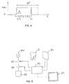
- the chronogram of the figure 4 allows to better illustrate the operation in time of the device.
- the timing chart indicates on the ordinate the supply voltage applied to the X-ray source of the X-ray device. It is considered that the source emits X-rays when the voltage is equal to the nominal power value V alim. On the abscissa, the chronogram indicates, in free scale, the time.
- ⁇ T The maximum duration of exposure, denoted ⁇ T, is set according to the maximum dose of X-rays that it is desired to administer to a patient. It is of the order of 80 to 200 milliseconds.
- FIGS. 5, 6 and 7 illustrate the use of a particular image acquisition feature, in the form of histograms. This illustration is given for the special case of dental radiography.
- the figure 5 shows a typical histogram of a correctly exposed dental X-ray, covering exactly the latitude of exposure available.
- the histogram indicates on the abscissa a range of density values, or gray levels, that continually extend from low densities (black), corresponding to transparent tissues, in the left part of the figure, to high densities (white ) corresponding to the opaque tissues, in the right part of the figure.
- the histogram indicates the number of pixels respectively corresponding to each density value. Since the sensor signal is converted to a digital signal, coded in this case as 12 bits, the density values range from 0 to 4095.
- a broken line B indicates a limit beyond the number of X photons. received is weak and the signal-to-noise ratio is degraded to the point of no longer distinguishing the X-rayed tissue.
- a first peak 501 of low density corresponds to the cheek of the patient.
- the envelope, or the spreading of a histogram comparable to that of the figure 5 can be used, for example as a reference acquisition characteristic.
- the figure 6 shows a histogram established during an intermediate reading of the pixels.
- the received dose is still low and the peaks of the histogram 601, 602, 603, 604, which correspond respectively to the peaks 501, 502, 503 and 504 of the figure 5 , are found on the side of high densities, that is to say, opaque materials. This is due to the small amount of light built in at this moment. This is, for example, the moment t1 of the figure 4 .
- the histogram evolves, the peaks become larger and the spreading increases in the direction indicated by an arrow to reach the shape of the figure 5 . At this point, exposure to X-rays can be suspended.
- the histogram evolves even more and takes a shape as represented in figure 7 . Only peaks 703 and 704, corresponding to peaks 503 and 504 of the figure 1 remain. The other peaks disappeared to the left side of the histogram. This reflects over-exposure or dazzle of the sensor, ie a complete discharge of the capacitor of an increasing number of its pixels.
- the histogram of the figure 5 can be used as a set histogram for a global examination of the oral cavity.
- the histogram of the figure 6 could be retained for examination limited to soft and transparent tissues, while that of the figure 7 could be used as a deposit for an examination of enamel or amalgam.
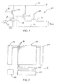
- the figure 8 represents in a simplified manner a device implementing the method described. It comprises an X-ray source indicated with reference 800, a CMOS sensor indicated with reference 810, a calculation unit 812, and a monitor 514.
- Calculation unit 812 for example a computer, or a unit dedicated, has several functions. One of the functions is to collect the sensor reading signal from the sensor 810 and to provide the sensor with read and refresh pulses. It integrates for this purpose a sequencer.
- the computing unit 812 also sets the image acquisition characteristics and compares them to a setpoint characteristic as already described. It can also use the read signals to format an image output by a monitor or screen 814 connected thereto.
- the computing unit controls two switches 816 and 817 connected in series in a supply circuit connecting a power source 818 to the X-ray source.
- the first switch 817 is designed to interrupt the X-ray emission. when a predetermined maximum duration ⁇ T is reached.
- the second switch is provided to interrupt the power supply when the target acquisition value is reached.
- the reference D symbolically represents tissues, in particular a tooth, located in the radiographic field between the source and the sensor.
- the sensor 810 is in particular an intraoral sensor.
Landscapes
- Health & Medical Sciences (AREA)
- Life Sciences & Earth Sciences (AREA)
- Engineering & Computer Science (AREA)
- Medical Informatics (AREA)
- General Health & Medical Sciences (AREA)
- Physics & Mathematics (AREA)
- Surgery (AREA)
- Public Health (AREA)
- Optics & Photonics (AREA)
- Pathology (AREA)
- Radiology & Medical Imaging (AREA)
- Biomedical Technology (AREA)
- Heart & Thoracic Surgery (AREA)
- Molecular Biology (AREA)
- High Energy & Nuclear Physics (AREA)
- Animal Behavior & Ethology (AREA)
- Biophysics (AREA)
- Nuclear Medicine, Radiotherapy & Molecular Imaging (AREA)
- Veterinary Medicine (AREA)
- Multimedia (AREA)
- Signal Processing (AREA)
- Toxicology (AREA)
- Mathematical Physics (AREA)
- Pulmonology (AREA)
- Theoretical Computer Science (AREA)
- Dentistry (AREA)
- Oral & Maxillofacial Surgery (AREA)
- Apparatus For Radiation Diagnosis (AREA)
Claims (11)
- Verfahren zum Regeln einer Röntgenstrahlenquelle (800) in einer Röntgenvorrichtung, die einen Bildaufnehmer (810) des MOS-Typs mit Pixeln (10) umfasst, die mit einer Lesesteuerung (30) und mit einer Auffrischungssteuerung (20), die voneinander unabhängig sind, versehen sind, dadurch gekennzeichnet, dass bei einem Röntgenbetrieb wiederholt die Lesesteuerungen mehrerer Pixel des Bildaufnehmers stimuliert werden und dabei die Röntgenstrahlenquelle gespeist wird, derart, dass in Reaktion auf jedes Lesen wenigstens ein Bilderfassungsmerkmal gebildet wird, wobei die Aussendung von Röntgenstrahlen unterbrochen wird, wenn das Bilderfassungsmerkmal einem Schwellen-Bilderfassungsmerkmal entspricht.
- Verfahren nach Anspruch 1, wobei das Bilderfassungsmerkmal ein Histogramm ist.
- Verfahren nach Anspruch 2, wobei das Schwellenmerkmal eine Histogrammform und insbesondere eine auf wenigstens einen von mehreren Peaks (501, 502, 503, 504, 601', 602, 603, 604, 703, 704) zentrierte Histogrammform ist, wobei die Peaks für Weichgewebe, Knochen und Zahnbein, für Emaille bzw. lichtundurchlässige Substanzen charakteristisch sind.
- Verfahren nach Anspruch 1, wobei das Bilderfassungsmerkmal eine Anzahl von Pixeln ist, die wenigstens einem Dichtewert des Bildes entspricht.
- Verfahren nach Anspruch 1, wobei das Bilderfassungsmerkmal eine Verbreiterung des Dichtespektrums, die einen Schwellenwert übersteigt, ist.
- Verfahren nach Anspruch 1, wobei Lesebefehle an sämtliche Pixel des Bildaufnehmers bzw. an eine Untergesamtheit von Pixeln des Bildaufnehmers gesendet werden und das Bilderfassungsmerkmal anhand von Lesesignalen für sämtliche Pixel bzw. für die Untergesamtheit von Pixeln des Bildaufnehmers gebildet wird.
- Verfahren nach Anspruch 6, wobei die Untergesamtheit von Pixeln Pixel umfasst, die auf der Oberfläche des Aufnehmers gleichmäßig verteilt sind.
- Verfahren nach Anspruch 1, wobei die Lesesteuerungen sequentiell stimuliert werden.
- Röntgenverfahren, das das Regelungsverfahren nach Anspruch 1 verwendet, wobei ein Lesen von Pixeln des Aufnehmers ausgeführt wird, wenn das Bilderfassungsmerkmal einem Schwellen-Bilderfassungsmerkmal entspricht, und ein Bild anhand eines beim Lesen erhaltenen Lesesignals erzeugt wird.
- Röntgenvorrichtung, die eine Röntgenstrahlenquelle (806) und einen Bildaufnehmer (810) des MOS-Typs mit Pixeln, die mit einer Lesesteuerung bzw. mit einer Auffrischungssteuerung, die voneinander unabhängig sind, versehen sind, eine Ablaufsteuerung, um in die Lesesteuerungen eine Reihe von Stimulationssignalen einzugeben, die auf eine Röntgenbestrahlungsperiode verteilt sind, und einen Rechner (812), der die von den Pixeln in Reaktion auf die Stimulationssignale gelieferten Lesesignale empfängt, um ein Bilderfassungsmerkmal zu schaffen und um das Erfassungsmerkmal mit einem Schwellen-Erfassungsmerkmal zu vergleichen, umfasst, dadurch gekennzeichnet, dass sie ein Mittel (817) zum Unterbrechen der Röntgenbestrahlung umfasst, die durch den Rechner gesteuert wird, um die Bestrahlung zu unterbrechen, wenn das Erfassungsmerkmal dem Schwellen-Bilderfassungsmerkmal entspricht.
- Vorrichtung nach Anspruch 10, die außerdem ein Mittel (814) zum Wiederherstellen eines Bildes umfasst, um ein Bild anhand von Lesesignalen, die von den Pixeln geliefert werden, zu erzeugen.
Priority Applications (6)
| Application Number | Priority Date | Filing Date | Title |
|---|---|---|---|
| EP05356199A EP1787585B1 (de) | 2005-11-15 | 2005-11-15 | X-ray source with a feedback loop in a radiography apparatus |
| DE602005007505T DE602005007505D1 (de) | 2005-11-15 | 2005-11-15 | X-ray source with a feedback loop in a radiography apparatus |
| KR1020087014464A KR101320161B1 (ko) | 2005-11-15 | 2006-10-19 | 디지털 방사선 사진 촬영 장치의 엑스선의 소스를서보제어하는 방법 |
| PCT/EP2006/010060 WO2007057083A1 (en) | 2005-11-15 | 2006-10-19 | Method for servoing a source of x-rays of a digital radiography device |
| JP2008539284A JP5822426B2 (ja) | 2005-11-15 | 2006-10-19 | デジタル放射線写真装置のx線源をサーボ制御する方法 |
| US12/093,456 US7860218B2 (en) | 2005-11-15 | 2006-10-19 | Method for servoing a source of X-rays of a digital radiography device |
Applications Claiming Priority (1)
| Application Number | Priority Date | Filing Date | Title |
|---|---|---|---|
| EP05356199A EP1787585B1 (de) | 2005-11-15 | 2005-11-15 | X-ray source with a feedback loop in a radiography apparatus |
Publications (2)
| Publication Number | Publication Date |
|---|---|
| EP1787585A1 EP1787585A1 (de) | 2007-05-23 |
| EP1787585B1 true EP1787585B1 (de) | 2008-06-11 |
Family
ID=35519970
Family Applications (1)
| Application Number | Title | Priority Date | Filing Date |
|---|---|---|---|
| EP05356199A Expired - Lifetime EP1787585B1 (de) | 2005-11-15 | 2005-11-15 | X-ray source with a feedback loop in a radiography apparatus |
Country Status (6)
| Country | Link |
|---|---|
| US (1) | US7860218B2 (de) |
| EP (1) | EP1787585B1 (de) |
| JP (1) | JP5822426B2 (de) |
| KR (1) | KR101320161B1 (de) |
| DE (1) | DE602005007505D1 (de) |
| WO (1) | WO2007057083A1 (de) |
Families Citing this family (3)
| Publication number | Priority date | Publication date | Assignee | Title |
|---|---|---|---|---|
| DK2459070T3 (da) | 2009-07-31 | 2020-06-02 | Dental Imaging Technologies Corp | Panorama-tandbilleddannelse med anvendelse af segmentering og en master-bue |
| KR20130049076A (ko) | 2011-11-03 | 2013-05-13 | 삼성디스플레이 주식회사 | 광검출 화소, 광검출 장치, 및 그 구동방법 |
| FI3673810T3 (fi) * | 2018-12-28 | 2023-12-15 | Sirona Dental Systems Gmbh | Hampaiden röntgenkuvausjärjestelmä suunsisäisten röntgenkuvien tuottamiseksi |
Family Cites Families (23)
| Publication number | Priority date | Publication date | Assignee | Title |
|---|---|---|---|---|
| US4030119A (en) * | 1975-10-01 | 1977-06-14 | General Electric Company | Video window control |
| US5018177A (en) * | 1989-06-01 | 1991-05-21 | Board Of Regents, The University Of Texas System | Apparatus and method for producing digital panoramic x-ray images |
| JPH07171142A (ja) * | 1993-12-21 | 1995-07-11 | Toshiba Corp | 放射線診断装置 |
| US5574764A (en) * | 1995-06-06 | 1996-11-12 | General Electric Company | Digital brightness detector |
| JP3670439B2 (ja) * | 1997-05-09 | 2005-07-13 | 株式会社日立メディコ | X線装置 |
| JP3578378B2 (ja) * | 1997-10-29 | 2004-10-20 | 株式会社日立メディコ | X線装置 |
| US6243441B1 (en) * | 1999-07-13 | 2001-06-05 | Edge Medical Devices | Active matrix detector for X-ray imaging |
| US6246745B1 (en) * | 1999-10-29 | 2001-06-12 | Compumed, Inc. | Method and apparatus for determining bone mineral density |
| JP3893827B2 (ja) * | 1999-11-26 | 2007-03-14 | コニカミノルタホールディングス株式会社 | X線画像撮影システム |
| US6404854B1 (en) * | 2000-06-26 | 2002-06-11 | Afp Imaging Corporation | Dental x-ray imaging system |
| US6307915B1 (en) * | 2000-06-26 | 2001-10-23 | Afp Imaging Corporation | Triggering of solid state X-ray imagers with non-destructive readout capability |
| JP3548507B2 (ja) * | 2000-08-01 | 2004-07-28 | キヤノン株式会社 | 放射線撮像装置 |
| JP3840050B2 (ja) * | 2000-11-01 | 2006-11-01 | キヤノン株式会社 | 電磁波変換装置 |
| US6895077B2 (en) * | 2001-11-21 | 2005-05-17 | University Of Massachusetts Medical Center | System and method for x-ray fluoroscopic imaging |
| FI113897B (fi) * | 2001-11-23 | 2004-06-30 | Planmed Oy | Automaattivalotusmenetelmä ja automaattivalotusjärjestelmä |
| JP2003250789A (ja) * | 2002-02-28 | 2003-09-09 | Canon Inc | 放射線撮影装置、プログラム、及びコンピュータ可読記憶媒体 |
| US6931098B2 (en) * | 2002-03-08 | 2005-08-16 | Ge Medical Systems Global Technology Company, Llc | Method and system for dual or multiple energy imaging |
| ITBO20020440A1 (it) * | 2002-07-05 | 2004-01-05 | Cefla Coop | Unita per l ' acquisizione e la visualizzazione di immagini radiografiche dentali |
| JP2004097465A (ja) * | 2002-09-09 | 2004-04-02 | Canon Inc | 放射線撮像装置 |
| JP3667317B2 (ja) * | 2002-11-26 | 2005-07-06 | キヤノン株式会社 | 放射線断層撮影装置 |
| JP4217505B2 (ja) * | 2003-02-28 | 2009-02-04 | キヤノン株式会社 | 撮像装置及びx線撮像装置 |
| JP2005143802A (ja) * | 2003-11-14 | 2005-06-09 | Konica Minolta Medical & Graphic Inc | 放射線画像読取装置 |
| JP4612796B2 (ja) * | 2004-01-30 | 2011-01-12 | キヤノン株式会社 | X線撮影画像表示制御装置及び方法並びにx線撮影システム |
-
2005
- 2005-11-15 EP EP05356199A patent/EP1787585B1/de not_active Expired - Lifetime
- 2005-11-15 DE DE602005007505T patent/DE602005007505D1/de not_active Expired - Lifetime
-
2006
- 2006-10-19 WO PCT/EP2006/010060 patent/WO2007057083A1/en not_active Ceased
- 2006-10-19 JP JP2008539284A patent/JP5822426B2/ja not_active Expired - Fee Related
- 2006-10-19 US US12/093,456 patent/US7860218B2/en active Active
- 2006-10-19 KR KR1020087014464A patent/KR101320161B1/ko not_active Expired - Fee Related
Also Published As
| Publication number | Publication date |
|---|---|
| JP5822426B2 (ja) | 2015-11-24 |
| US20090220044A1 (en) | 2009-09-03 |
| EP1787585A1 (de) | 2007-05-23 |
| KR101320161B1 (ko) | 2013-10-23 |
| KR20080082643A (ko) | 2008-09-11 |
| JP2009515573A (ja) | 2009-04-16 |
| DE602005007505D1 (de) | 2008-07-24 |
| US7860218B2 (en) | 2010-12-28 |
| WO2007057083A1 (en) | 2007-05-24 |
Similar Documents
| Publication | Publication Date | Title |
|---|---|---|
| EP0817472B1 (de) | Verfahren und Vorrichtung zur Aufnahme von Röntgen- und Gammastrahlen-Bildern mit Optimierung der Belichtungszeit | |
| RU2379712C1 (ru) | Устройство формирования изображений методом излучения, способ управления для него и машиночитаемый носитель, хранящий программу осуществления способа | |
| US5818898A (en) | X-ray imaging apparatus using X-ray planar detector | |
| EP0830619B1 (de) | Röntgenstrahlungs-bildsensor | |
| EP1532927B1 (de) | Zahnärztliches Röntgengerät | |
| FR2832015A1 (fr) | Procede d'identification et de correction de pixel ayant une remanence excessive dans un detecteur de rayons x a l'etat solide. | |
| US6920198B2 (en) | Methods and apparatus for processing a fluoroscopic image | |
| FR2837053A1 (fr) | Procede et systeme d'imagerie bi ou multi-energetique | |
| US20080049900A1 (en) | Radiography apparatus, radiography system, and control method thereof | |
| EP1006719A1 (de) | Verfahren zur Korrektur von Bildartefakten in einem Röntgenstrahlen- oder Gammastrahlendetektor | |
| WO2016120091A1 (fr) | Capteur radiologique avec detection de rayons x | |
| EP1760793B1 (de) | Energieselektiver Röntgendetektor | |
| JP2985731B2 (ja) | X線撮像装置 | |
| EP3193724A1 (de) | Verfahren und anordnung zur aufnahme von medizinischen röntgenbildern mit steuerung des stoppvorgangs der röntgenquelle | |
| US6477228B2 (en) | Method for operating an X-ray diagnosis device with immediate imaging | |
| US7164115B2 (en) | Photoelectric conversion apparatus, manufacturing method therefor, and X-ray imaging apparatus | |
| EP1787585B1 (de) | X-ray source with a feedback loop in a radiography apparatus | |
| US7659517B2 (en) | Method and apparatus for triggering image acquisition in radiography | |
| FR2839231A1 (fr) | Procede et appareil pour accroitre la frequence d'accquisition de donnees dans un detecteur numerique. | |
| JP4707986B2 (ja) | ディジタルx線検出器によって撮影されたx線画像の補正方法、x線検出器の較正方法およびx線装置 | |
| EP1537826B1 (de) | Verfahren zur Signalverarbeitung in einem Dental-Radiologiegerät | |
| JP2009284181A (ja) | 固体撮像装置 | |
| EP2315434B1 (de) | Festkörper-bildgeber und einzelbilddatenkorrekturverfahren | |
| FR2791445A1 (fr) | Procede et dispositif pour la compensation de charge de balayage dans un detecteur numerique | |
| FR2819135A1 (fr) | Procede et dispositif pour corriger le decalage induit par des effets photoconducteurs de transistors a effet de champ dans un detecteur de rayons x a semi conducteur |
Legal Events
| Date | Code | Title | Description |
|---|---|---|---|
| PUAI | Public reference made under article 153(3) epc to a published international application that has entered the european phase |
Free format text: ORIGINAL CODE: 0009012 |
|
| 17P | Request for examination filed |
Effective date: 20060711 |
|
| AK | Designated contracting states |
Kind code of ref document: A1 Designated state(s): AT BE BG CH CY CZ DE DK EE ES FI FR GB GR HU IE IS IT LI LT LU LV MC NL PL PT RO SE SI SK TR |
|
| AX | Request for extension of the european patent |
Extension state: AL BA HR MK YU |
|
| RAP1 | Party data changed (applicant data changed or rights of an application transferred) |
Owner name: TROPHY |
|
| GRAP | Despatch of communication of intention to grant a patent |
Free format text: ORIGINAL CODE: EPIDOSNIGR1 |
|
| GRAS | Grant fee paid |
Free format text: ORIGINAL CODE: EPIDOSNIGR3 |
|
| AKX | Designation fees paid |
Designated state(s): DE ES FI FR GB IT |
|
| GRAA | (expected) grant |
Free format text: ORIGINAL CODE: 0009210 |
|
| AK | Designated contracting states |
Kind code of ref document: B1 Designated state(s): DE ES FI FR GB IT |
|
| REG | Reference to a national code |
Ref country code: GB Ref legal event code: FG4D Free format text: NOT ENGLISH |
|
| REF | Corresponds to: |
Ref document number: 602005007505 Country of ref document: DE Date of ref document: 20080724 Kind code of ref document: P |
|
| PG25 | Lapsed in a contracting state [announced via postgrant information from national office to epo] |
Ref country code: ES Free format text: LAPSE BECAUSE OF FAILURE TO SUBMIT A TRANSLATION OF THE DESCRIPTION OR TO PAY THE FEE WITHIN THE PRESCRIBED TIME-LIMIT Effective date: 20080922 |
|
| PLBE | No opposition filed within time limit |
Free format text: ORIGINAL CODE: 0009261 |
|
| STAA | Information on the status of an ep patent application or granted ep patent |
Free format text: STATUS: NO OPPOSITION FILED WITHIN TIME LIMIT |
|
| 26N | No opposition filed |
Effective date: 20090312 |
|
| PG25 | Lapsed in a contracting state [announced via postgrant information from national office to epo] |
Ref country code: IT Free format text: LAPSE BECAUSE OF FAILURE TO SUBMIT A TRANSLATION OF THE DESCRIPTION OR TO PAY THE FEE WITHIN THE PRESCRIBED TIME-LIMIT Effective date: 20080611 |
|
| REG | Reference to a national code |
Ref country code: FR Ref legal event code: ST Effective date: 20090731 |
|
| REG | Reference to a national code |
Ref country code: FR Ref legal event code: RN |
|
| REG | Reference to a national code |
Ref country code: FR Ref legal event code: FC |
|
| REG | Reference to a national code |
Ref country code: FR Ref legal event code: PLFP Year of fee payment: 11 |
|
| REG | Reference to a national code |
Ref country code: FR Ref legal event code: PLFP Year of fee payment: 12 |
|
| REG | Reference to a national code |
Ref country code: FR Ref legal event code: PLFP Year of fee payment: 13 |
|
| REG | Reference to a national code |
Ref country code: FR Ref legal event code: PLFP Year of fee payment: 14 |
|
| PGFP | Annual fee paid to national office [announced via postgrant information from national office to epo] |
Ref country code: FI Payment date: 20191028 Year of fee payment: 15 |
|
| PGFP | Annual fee paid to national office [announced via postgrant information from national office to epo] |
Ref country code: GB Payment date: 20191029 Year of fee payment: 15 |
|
| REG | Reference to a national code |
Ref country code: FI Ref legal event code: MAE |
|
| GBPC | Gb: european patent ceased through non-payment of renewal fee |
Effective date: 20201115 |
|
| PG25 | Lapsed in a contracting state [announced via postgrant information from national office to epo] |
Ref country code: FI Free format text: LAPSE BECAUSE OF NON-PAYMENT OF DUE FEES Effective date: 20201115 |
|
| PG25 | Lapsed in a contracting state [announced via postgrant information from national office to epo] |
Ref country code: GB Free format text: LAPSE BECAUSE OF NON-PAYMENT OF DUE FEES Effective date: 20201115 |
|
| PGFP | Annual fee paid to national office [announced via postgrant information from national office to epo] |
Ref country code: FR Payment date: 20221020 Year of fee payment: 18 |
|
| PGFP | Annual fee paid to national office [announced via postgrant information from national office to epo] |
Ref country code: DE Payment date: 20221012 Year of fee payment: 18 |
|
| REG | Reference to a national code |
Ref country code: DE Ref legal event code: R119 Ref document number: 602005007505 Country of ref document: DE |
|
| PG25 | Lapsed in a contracting state [announced via postgrant information from national office to epo] |
Ref country code: DE Free format text: LAPSE BECAUSE OF NON-PAYMENT OF DUE FEES Effective date: 20240601 |
|
| PG25 | Lapsed in a contracting state [announced via postgrant information from national office to epo] |
Ref country code: FR Free format text: LAPSE BECAUSE OF NON-PAYMENT OF DUE FEES Effective date: 20231130 |
|
| PG25 | Lapsed in a contracting state [announced via postgrant information from national office to epo] |
Ref country code: FR Free format text: LAPSE BECAUSE OF NON-PAYMENT OF DUE FEES Effective date: 20231130 Ref country code: DE Free format text: LAPSE BECAUSE OF NON-PAYMENT OF DUE FEES Effective date: 20240601 |