EP1787704A2 - Dispositif pour la filtration des microparticules - Google Patents
Dispositif pour la filtration des microparticules Download PDFInfo
- Publication number
- EP1787704A2 EP1787704A2 EP06023725A EP06023725A EP1787704A2 EP 1787704 A2 EP1787704 A2 EP 1787704A2 EP 06023725 A EP06023725 A EP 06023725A EP 06023725 A EP06023725 A EP 06023725A EP 1787704 A2 EP1787704 A2 EP 1787704A2
- Authority
- EP
- European Patent Office
- Prior art keywords
- cells
- fluid
- cell
- particles
- flange
- Prior art date
- Legal status (The legal status is an assumption and is not a legal conclusion. Google has not performed a legal analysis and makes no representation as to the accuracy of the status listed.)
- Ceased
Links
Images


Classifications
-
- B—PERFORMING OPERATIONS; TRANSPORTING
- B01—PHYSICAL OR CHEMICAL PROCESSES OR APPARATUS IN GENERAL
- B01D—SEPARATION
- B01D45/00—Separating dispersed particles from gases or vapours by gravity, inertia, or centrifugal forces
- B01D45/12—Separating dispersed particles from gases or vapours by gravity, inertia, or centrifugal forces by centrifugal forces
-
- B—PERFORMING OPERATIONS; TRANSPORTING
- B01—PHYSICAL OR CHEMICAL PROCESSES OR APPARATUS IN GENERAL
- B01D—SEPARATION
- B01D46/00—Filters or filtering processes specially modified for separating dispersed particles from gases or vapours
- B01D46/24—Particle separators, e.g. dust precipitators, using rigid hollow filter bodies
- B01D46/2403—Particle separators, e.g. dust precipitators, using rigid hollow filter bodies characterised by the physical shape or structure of the filtering element
- B01D46/2407—Filter candles
-
- B—PERFORMING OPERATIONS; TRANSPORTING
- B01—PHYSICAL OR CHEMICAL PROCESSES OR APPARATUS IN GENERAL
- B01D—SEPARATION
- B01D46/00—Filters or filtering processes specially modified for separating dispersed particles from gases or vapours
- B01D46/56—Filters or filtering processes specially modified for separating dispersed particles from gases or vapours with multiple filtering elements, characterised by their mutual disposition
- B01D46/58—Filters or filtering processes specially modified for separating dispersed particles from gases or vapours with multiple filtering elements, characterised by their mutual disposition connected in parallel
-
- F—MECHANICAL ENGINEERING; LIGHTING; HEATING; WEAPONS; BLASTING
- F01—MACHINES OR ENGINES IN GENERAL; ENGINE PLANTS IN GENERAL; STEAM ENGINES
- F01N—GAS-FLOW SILENCERS OR EXHAUST APPARATUS FOR MACHINES OR ENGINES IN GENERAL; GAS-FLOW SILENCERS OR EXHAUST APPARATUS FOR INTERNAL-COMBUSTION ENGINES
- F01N13/00—Exhaust or silencing apparatus characterised by constructional features
- F01N13/009—Exhaust or silencing apparatus characterised by constructional features having two or more separate purifying devices arranged in series
- F01N13/0097—Exhaust or silencing apparatus characterised by constructional features having two or more separate purifying devices arranged in series the purifying devices are arranged in a single housing
-
- F—MECHANICAL ENGINEERING; LIGHTING; HEATING; WEAPONS; BLASTING
- F01—MACHINES OR ENGINES IN GENERAL; ENGINE PLANTS IN GENERAL; STEAM ENGINES
- F01N—GAS-FLOW SILENCERS OR EXHAUST APPARATUS FOR MACHINES OR ENGINES IN GENERAL; GAS-FLOW SILENCERS OR EXHAUST APPARATUS FOR INTERNAL-COMBUSTION ENGINES
- F01N3/00—Exhaust or silencing apparatus having means for purifying, rendering innocuous, or otherwise treating exhaust
- F01N3/02—Exhaust or silencing apparatus having means for purifying, rendering innocuous, or otherwise treating exhaust for cooling, or for removing solid constituents of, exhaust
- F01N3/021—Exhaust or silencing apparatus having means for purifying, rendering innocuous, or otherwise treating exhaust for cooling, or for removing solid constituents of, exhaust by means of filters
- F01N3/0212—Exhaust or silencing apparatus having means for purifying, rendering innocuous, or otherwise treating exhaust for cooling, or for removing solid constituents of, exhaust by means of filters with one or more perforated tubes surrounded by filtering material, e.g. filter candles
-
- F—MECHANICAL ENGINEERING; LIGHTING; HEATING; WEAPONS; BLASTING
- F01—MACHINES OR ENGINES IN GENERAL; ENGINE PLANTS IN GENERAL; STEAM ENGINES
- F01N—GAS-FLOW SILENCERS OR EXHAUST APPARATUS FOR MACHINES OR ENGINES IN GENERAL; GAS-FLOW SILENCERS OR EXHAUST APPARATUS FOR INTERNAL-COMBUSTION ENGINES
- F01N3/00—Exhaust or silencing apparatus having means for purifying, rendering innocuous, or otherwise treating exhaust
- F01N3/02—Exhaust or silencing apparatus having means for purifying, rendering innocuous, or otherwise treating exhaust for cooling, or for removing solid constituents of, exhaust
- F01N3/021—Exhaust or silencing apparatus having means for purifying, rendering innocuous, or otherwise treating exhaust for cooling, or for removing solid constituents of, exhaust by means of filters
- F01N3/031—Exhaust or silencing apparatus having means for purifying, rendering innocuous, or otherwise treating exhaust for cooling, or for removing solid constituents of, exhaust by means of filters having means for by-passing filters, e.g. when clogged or during cold engine start
-
- Y—GENERAL TAGGING OF NEW TECHNOLOGICAL DEVELOPMENTS; GENERAL TAGGING OF CROSS-SECTIONAL TECHNOLOGIES SPANNING OVER SEVERAL SECTIONS OF THE IPC; TECHNICAL SUBJECTS COVERED BY FORMER USPC CROSS-REFERENCE ART COLLECTIONS [XRACs] AND DIGESTS
- Y02—TECHNOLOGIES OR APPLICATIONS FOR MITIGATION OR ADAPTATION AGAINST CLIMATE CHANGE
- Y02T—CLIMATE CHANGE MITIGATION TECHNOLOGIES RELATED TO TRANSPORTATION
- Y02T10/00—Road transport of goods or passengers
- Y02T10/10—Internal combustion engine [ICE] based vehicles
- Y02T10/12—Improving ICE efficiencies
Definitions
- the invention refers to an apparatus for filtering micro particles, comprising tubular cells, wherein a first end of each cell is open to let a fluid enter from a distribution area into the cell and a second end of each cell is closed, the fluid being forced to change direction of flow from axial to radial for vacating the cell through a cell mantle into an escape area, and wherein the tubular cells form a package supported by a flange, the flange enveloping the package and separating the distribution area from the escape area.
- This invention refers to a filter for trapping solid particles contained in high pressure and temperature gases. Microparticles are emitted by sources, such as grinding processes, sublimation from smelting process, emissions from inner combustion engines, high pressure and temperature reactors, boilers, chimneys, etc. It also becomes more and more necessary to trap effectively the residues emitted by combustion vehicles.
- the retention of particulate material at vehicle exhausts involves the problems, that particles are of microscopic sizes of about 160 ⁇ to 900 ⁇ (160x10 -10 m to 900x10 -10 m), and the fact that engine residue is ejected at high temperatures of about 300 °C to 400 °C and high pressures (306.122 kilopond/m 2 ).
- the objective of the present invention is to provide an apparatus for filtering micro particles contained in high pressure, high temperature gases, in which the deficiencies mentioned above are reduced or eliminated, and which is produced at reasonable costs, thus solving for example the technical problems of high speed escape or the inconvenience of introduction of an excessive counter pressure to the escape fluids or the extremely small size of the solid particles of the fluid or the high fluid temperature and pressure.
- An apparatus for filtering micro particles emitted by any micro-particle-emitting source such as grinding mills, smelting process sublimation, internal combustion engines, high pressure / temperature reactors, boilers, stacks, etc comprises the following components: an assembly of tubular cells which could for example be cylindrical, square, rectangular or polygonal.
- the cell arrangement designed to force a fluid inside the cell through the a first end of the cell and to exit through a cell mantle because the other, second end of the cell is closed.
- One or more tubular cells preferably comprise a relief valve installed at the second end.
- the relief valve is designed to operate at a certain exhaust back pressure that, for example, can damage the system that generates the exhaust gas or fluid, or the filter itself.
- the tubular cells are distributed to form a package or group supported by a flange, enveloping the package, preferably inside of a casing that contains and protects the bundle or package of tubes.
- the support flange and the casing together form a tight chamber which forces the fluid, for example exhaust gas to enter the tubular cells following an axial direction, and allows the fluid to vacate from the cells towards an escape area following a radial direction.
- the escape area or chamber is for example a section of the casing, which is separated from a distribution area by the cell support flange, which supports the package of cells, preferably in parallel.
- the change of direction of flow of the fluid from axial to radial reduces the speed of the fluid down to such a level that micro particles can settle over a retaining cloth and gradually fill up interstices in the retaining cloth and spaces between the retaining cloths.
- the number of cells and the individual cell mantle area which depends upon the number of layers of retaining cloth wrapped around the cell mantle, are the factors governing the speed of saturation. These two factors are defined when calculating the requirements of each particular case in order to allow the particle flow to pass through the retention cloth layers and to change the direction of the flow from longitudinal to radial.
- the design of the cells takes the velocity of the fluid to a limit very close to zero, which as a physical consequence, reduces the kinetic energy of the particles to a level closer to zero.
- One important aspect of the invention is to provide a low differential pressure or pressure loss between the inside and the outside of the cell. Once the fluid has vacated the cell, it recovers velocity. The differential pressure of the cell can become seriously affected, if the fluid flow is interfered by obstacles in its way outside the cell.
- the inventive cell design allows a high filtration surface, without the proximity of the cells causing the retaining cloths to approach each other too close. The distance should for example not be of less than about 3 mm. A blockade of the intercellular flow and a subsequent increase of the loss of pressure of the system is thereby prevented.
- the inventive apparatus provides an efficient trapping of micro particles issued for example from any ontogenic or geogenic source.
- the remarkable effect of speed reduction, that the cells produce allows for example that the retention cloth traps the micro particles easily.
- the micro particles reach a speed near zero in the axial direction, approximately at the moment when they change direction of flow to the perpendicular, i.e. radial direction of flow towards the cell mantle, which produces a non negligible retaining effect.
- the cells preferably comprise a supporting structure, which consist in a perforated metal tube, spread metal or a structurally self-supporting metal mesh, and the supporting structure is wrapped around with layers of the retaining cloth, which is resistant to exhaust gas/fluid temperature and pressure.
- a part of the first end of each cell projects through an opening in the supporting flange, the part of the first end preferably being bent in angle of about 90° outwardly from the cell axis, the bent parts preferably being welded to the supporting flange and/or a neighbouring bent part of a first end.
- the first ends of the cells form a rectangular and a metal tape, that surrounds the rectangular, is welded to the outwardly facing walls of the cells.
- the apparatus needs to be well structured, to be able for example to resist the extreme vibrations when it is applied for example in mobile sources as trucks, buses, or ships, or, when being static, the fluid or exhaust issuing sources originate high degrees of vibration, for example in Diesel generators of high power, ovens or large kilns.
- the required resistance is improved by the reinforcement of each cell, by bending in about two millimeters of the metal which enforces the structure of the cell in both extremes all around the upper edge of the first end. Welding the metal of the cell to the metal of the flange, and welding all the cells of the package in the central point of every set of four cells further improves stability.
- An external rectangular or square ring, which surrounds the matrix conformed by the package of cells, is also welded to the side walls of the cells. In this way, a virtual column is conformed, giving a high vibration resistance to the package of cells.
- a thermal fabric layer made of mineral wool covers the inside of the second end of the cells in such a way that the thermal fabric layer penetrates the inside space of the cells in a distance of about 0.01 m or more, the thermal fabric layer preferably covering the second ends of a multitude of cells, the second ends being closed by a steel plate, which is pressed against the thermal fabric layer and in that position is welded to the second ends of the cells.
- This provides that there will be less leakage of gases through the second ends of the cells, which is an important aspect of the invention.
- the enclosure of the fluids in each cell inside the casing depends upon a tight sealing of the blind extreme of the cells. If fluid could escape avoiding the retaining cloth, it would transport the accumulated powdered material stocked inside the cell to the outer atmosphere. This is widely prevented by the thermal fabric layer.
- each cell supporting structure is made of spread metal or fine metal mesh in such a way that it allows particulate material to settle over, and accumulate in, mesh spaces, establishing a limit between the already settled material that is permanently accumulated on and between cloth layers on the one hand, and the particulate material that builds up from the metal mesh towards the cylindrical cell centerline or axis on the other hand.
- the cells have to be cleaned periodically, to remove at least the latter particulate material.
- the retaining cloth is arranged as to form a stereo mesh, the retaining cloth comprising visible spaces and being wrapped around itself, thereby forming a labyrinth in the radial flow direction of the fluid.
- the arrangement of the retaining cloth to form a stereo mesh i.e. instead of manufacturing an ultra fine metal mesh using traditional systems is less expansive.
- a retaining cloth with visible spaces is wrapped around itself forming a labyrinth that follows the radial flow direction and is for example more efficient than that obtained with a flat mesh.
- This labyrinth has a low load loss coefficient or, using filtering terminology, a high gas permeability.
- the cells gradually produce an interlayer filling formed by the particulate material, being able to trap particles sized 500 ⁇ and smaller, preferably smaller than the particles that form the reticule. Further it is preferred that the speed of the fluid is reduced down to such a level that the low kinetic energy of the retained particles prevents them from getting packed and/or forming hardened layers.
- the number of layers of retention cloth wrapped around the supporting structure is preferably varied from one layer up to the number of layers producing an exhaust gas back pressure allowed by the system that generates the exhaust gas or fluid.
- the stereo mesh has the beneficial ability to trap micro particles which cannot escape due to their low kinetic energy resulting from the multiplicity of cells. Additionally, the cells produce gradually an interlayer filling formed by the particulate material, which is able to trap particles sized 500 ⁇ and smaller, especially smaller than the particles that form the reticule.
- the number of wraps of retention cloth around the cell mantle is varied from one wrap up to the number of wraps allowed by the loss of load available in the system, i.e. the system constructs by itself a highly permeable micro porous medium.
- the low kinetic energy of the retained particles preferably prevents them from getting packed or forming hardened layers as it may happen in systems that provide the micro porous mediums synthetically.
- the flange supporting the cells acts as a base and a diverter inside the casing, the casing together with the flange allowing the fluid to follow only one way, with no possible alternative, towards the interior of the cells, and further out of the casing after the fluid having deposited its particulate material inside the cells; wherein the cells are preferably removable from the casing, in order to be cleaned and reinstalled later into the casing.
- a primary set of cells is serially arranged with a secondary set of cells, the secondary set of cells containing the same or different number of cells than the primary set, and that preferably the primary and secondary sets of cells are serially arranged with further sets of cells, wherein the limit of serially arranged sets of cells is the exhaust gas back pressure allowed by the system that generates the exhaust gas or fluid.
- the only limit is the loss of load available in the system in order to maintain an acceptable flow of fluid.
- the cells may as well be arranged parallely, or in series with a different filtering system, which for example provides a previous treatment of the fluid.
- a different filtering system which for example provides a previous treatment of the fluid.
- the particulate material trapped inside the cells is self-modified by the environment conditions as for example deliquescence, the property of some materials by which they can absorb atmospheric water. Due to a high hygroscopic capacity of the retained powder a metamorphic change in the structure of the powder might for example cement the retaining cloth of the cells.
- Fine contact of water drops is achieved inside a hydrocyclonic device with sprinklers oriented in radial position.
- the blockade of internal circuits of the sprinkler is avoided by the sprinkler atomizing the water by shooting a fine stream of water at high pressure against a needle in the outside.
- the impact of the stream against the head of the needle atomizes the water in a cloud of extremely fine particles.
- the shape of the outer side of the jet is parabolic in order to allow the cloud of particles to vacate from the sprinkler.
- the throat of the jet, which shoots against the head of the needle is about 1,5 mm in diameter and is protected with a metal mesh filter whose mesh is below 0,5 mm size.
- the sprinkler is oriented in an angle of about 45°, relative of the centrifugal circulation of the fluid flow with respect of the radial position of the sprinkler and oriented towards the perimetric walls of the cyclone.
- the centrifugal force acts over the particles in the fluid flow.
- the particles settle in the perimetric wall of the cyclone which is covered with a descendent layer of water which retains the powder and inhibits its return to the fluid flow.
- the efficiency of this combination of effects in one device and in a simultaneous process is for example over 96% of particle retention. After this treatment, which captures almost the 96% of the particles, the residue or difference is, for example, trapped by the dry system without any damage to its cells.
- Figure 1 shows the essential aspect of the invention, which is the fundamental basic cell 1.
- the different technical solutions will be simple combinations and/or variations of cell size, geometry and total number, arranged in series or in parallel.
- the option of an arrangement in series for self-contained filtering units will depend on the agreeable exhaust back pressure, or the loss of load available in the system, because two identical units combined in series for example need twice the amount of pressure in order to maintain a steadfast gas flow.
- the advantage of a serial arrangement is to increase retention capacity in an equivalent factor applied to the particulate material not retained in the first stage. For example, if the first module retains about 90% of particulate material, the option of two identical modules in series will retain about 99% of particulate material.
- the option in parallel will also increase the retention capacity without increasing loss of load; therefore, it is the adequate option when there is only a limited amount of pressure for fluid to be moved.
- the cells 1 can be fabricated of steel, stainless steel or plastic materials according to conditions of corrosion, temperature and pressure of fluid or filters.
- the basic cell 1 consists of a cylindrical spread-or-fine-mesh-metal column 3 with 1 mm 2 to 10 mm 2 orifices which will support the retention cloth 2 and supply a cavity for accumulated material 4.
- the fluid flow is forced by the support flange 6 to enter the basic cell 1 through the center of a first end and exit through the cylindrical mantle because the other, second end of the basic cell 1 is blocked.
- the solid particles contained in the fluid start to accumulate in cloth interstices and intercloth spaces, thus forming a retention layer able to trap increasingly small particles as intercloth spaces become more and more saturated.
- the cloths 2 will be fixed to the column 3, inside and outside, by means of adequate clamps.
- the retaining cloth 2 can be fabricated of steel, stainless steel or plastic materials according to conditions of corrosion, temperature and pressure of fluid or filters.
- the support flange 6 performs two essential functions, a) it anchors tightly the basic cells 1, and b) it prevents the fluid to exit along a path different from the inside of the cell 1, which is possible because the support flange 6 is tightly welded to the casing walls 10 as shown by Figure 3.
- the support flange 6 is made of stainless steel, for the sake of durability. Flange thickness is determined as per mechanic and structural design for the intended application; flange geometry can be square, rectangular, elliptic, or any other shape more convenient for the application.
- Figure 3 shows a specific solution wherein the cells 1 are distributed within the casing 10, allowing the incoming fluid flow to circulate only inside them, because the support flange 6 prevents any other possibility, pass through the shell towards the inside of the casing 10 and exit the system through the upper opening 11.
- the casing 10 can be fabricated of steel, stainless steel or plastic materials according to conditions of corrosion, temperature and pressure of fluid or filters.
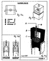
- FIG 4 shows a safety valve, which comprises the following elements: a closing piston (A) actuated by a spring at "D”, a closing piston guide bushing (B), a support frame (C) welded to the cell at "G”, a calibrated spring (D) to close piston “A”, some primary retaining cloth (E), a supporting spread and perforated metal mesh (F); where at point (P) the inside pressure, by overcoming spring "D” will open piston "A”.
- the invention consists of the design and construction of a filter to retain or trap the solid particles contained in high pressure and high temperature exhaust gas.
- the invention consists of the basic cells, Figure 1, the support and fluid distribution flange, Figure 2, and the casing, Figure 3.
- the invention includes at least one, preferably two or three safety valves that are installed at the cell closed, second ends, allowing the fluids to escape freely towards the inside of the casing and exit freely to the atmosphere, thus avoiding damage to engine and to the inventive apparatus itself, and supplying a signal when the latter has to be cleaned.
- the basic cell performs the function to reduce fluid speed so as to retain solids by means of loss of kinetic energy. Such effect is possible because of the big perpendicular surface versus flow; this is obtained through the multiplicity of basic cells arranged in parallel. All of this can be shown by means of the following equation:
- An ordinary bus engine emits around 110 l/sec exhaust gas through a 0.0762 m diameter ( ⁇ ) duct, at a mean speed of about 24,12 m/sec.
- the particles slow down along the axial or longitudinal centerline of the cells and reach a speed of about 0 almost at the time the fluid flow changes direction to follow the perpendicular, radial path towards the mantle, which enhances the retention effect.
- the retention system itself is located inside the equipment.
- the retention area proved to be adequate for meeting in excess the requirements specified by the Chilean norm in force at the time of the experiment.
- the equipment was installed at the end of a big vehicle (truck) tailpipe.
- Installation and cleaning proved to be easy. Installation took no longer than one hour. Subsequent cleaning operation did not take more than 30 minutes including equipment taking off, cleaning and reinstallation.
- the filter was installed in a 320-HP-turbomotor, Model 19231, year 1984, MAN truck.
- particle emission for this type of motor is 4,2 m -1 ; this level corresponds to a previous calibration of the opacimeter carried out with gas flows containing different particulate material concentrations.
- a motor of the latest technology in the market should not exceed 1,6 m -1 .
- a MAHA, type MDO2 opacimeter was used, same brand and type used by all checkup plants and Ministerio de Transportes and Carabineros de Chile mobile units.
- the opacimeter operates basically with a photoelectric cell, which receives a higher or lower amount of light depending on the particle load contained in the gas sample coming in through the suction probe. This operation is carried out in a dark chamber in order to suppress the effect of exterior light and mainly the effect of white particles that, by reflecting exterior light, increase the amount of light on the photocell and produce contradictory results.
- the equipment is previously calibrated according to the characteristics of the motors to be inspected in order to determine a scale which will act as the pattern. As already noted, presently there are three levels of requirement depending on motor technology and fabrication year: 4,2 m -1 for turbo motors without gas retention system, 2,2 m -1 for turbo motors with gas retention system, 1,6 m -1 latest generation ecological motors.
- the motor is accelerated from idle to +/- 4.000/4.500 rpm in 7 seconds; during this time up to 5 measurements can be taken automatically by the equipment. If two consecutive measurements differ by less than 0.5, the equipment considers that measurement as correct. If this is not the situation, measurements are automatically discarded.
- Valid measurements will be those two showing a difference equal to, or less than 0.5.
- the equipment will issue the verdict "approved” every time that coherent measurements (difference less than 0.5) are within the limit established according to type of motor, and adequately set in the opacimeter microprocessor.
- the opacimeter When coherent data are not obtained, or those having been obtained are higher than the accepted limit, the opacimeter will issue the verdict "not approved" together with the list of measurements.
- the filter reaches its maximum retention capacity after reaching some level of saturation because it operates according to the inventive general principle, i.e. the material already accumulated acts as the main retaining element.
- the filter original retention capacity a measurement was made immediately after installing the filter.
- Gas emission was also measured without filter in order to determine the motor pollution level at the time.
- the measurement shows a pollution index 2,9 times less than the motor pollution index without filtering element.
- the index reached with the filter just installed is much lower than that required by the norm for latest generation ecological vehicles, 1.6 m -1 .
- the equipment was disassembled to check the relief system, which was in perfect condition. However, an anomaly between measurement procedure and filter operative system was detected.
- the accumulated particulate material gets loose by the stroke pressure wave, is released, and joins the exhaust flow.
- the opacimeter measures the particles originated during the present combustion plus the particles originated in past combustions and already accumulated at the post-filtering zone.
- the acceleration procedure was, then, corrected to prevent the pressure stroke from occurring and action has been taken so as to prevent the post-filtering material from causing disturbances to the measurements taken by the opacimeter.
- the weight of the particulate material retained by the filter at 3122 km was: 1284,93 g that is 0.41157 g/km.
- the requested filter prevented the following number of micro particles from joining the breathable atmosphere: 3.589.189.900.000.000.000
- Soot or black smoke discharged by imperfect combustion engines is actually native carbon forming a sort of molecular clot with characteristics similar to graphite.
- Some types of soot contain very small micro crystals (so small that contain only a few graphite-structured cells).
- the physical properties of these materials are determined mainly by the nature and size of material surface. Finely divided forms with relatively big surfaces and attraction forces only partially saturated easily absorb huge amounts of gas and solute from solutions. This property, which in the case of gas retention in a solid because of the effect of surface forces superposed to molecular unsaturated forces, is called adsorption, and it is a subsidiary effect of the particle retention filter because it works as a gas mask and traps considerable amounts of combustion gas once the optimum filter saturation level has been reached.
- An average particle size of 525 ⁇ will be chosen; however, as soot particles are produced at high pressure and temperature, it is probable that the sizes of micro crystals will tend to be smaller than the average, not bigger.
- a cubic particle formed of parallel layers, 3.35 ⁇ apart from each other, will be considered. The distance between carbon atoms has been established as being 1,415 ⁇ . The joining angle between lines of the same layer will be 45°.
- NCp Number of carbon atoms per particle
Landscapes
- Engineering & Computer Science (AREA)
- Chemical & Material Sciences (AREA)
- Chemical Kinetics & Catalysis (AREA)
- Combustion & Propulsion (AREA)
- Mechanical Engineering (AREA)
- General Engineering & Computer Science (AREA)
- Physics & Mathematics (AREA)
- Geometry (AREA)
- Apparatus Associated With Microorganisms And Enzymes (AREA)
- Processes For Solid Components From Exhaust (AREA)
- Filtering Of Dispersed Particles In Gases (AREA)
- Filtering Materials (AREA)
Priority Applications (1)
| Application Number | Priority Date | Filing Date | Title |
|---|---|---|---|
| EP06023725A EP1787704A3 (fr) | 2005-11-17 | 2006-11-15 | Dispositif pour la filtration des microparticules |
Applications Claiming Priority (2)
| Application Number | Priority Date | Filing Date | Title |
|---|---|---|---|
| EP05110904 | 2005-11-17 | ||
| EP06023725A EP1787704A3 (fr) | 2005-11-17 | 2006-11-15 | Dispositif pour la filtration des microparticules |
Publications (2)
| Publication Number | Publication Date |
|---|---|
| EP1787704A2 true EP1787704A2 (fr) | 2007-05-23 |
| EP1787704A3 EP1787704A3 (fr) | 2007-06-20 |
Family
ID=37672466
Family Applications (1)
| Application Number | Title | Priority Date | Filing Date |
|---|---|---|---|
| EP06023725A Ceased EP1787704A3 (fr) | 2005-11-17 | 2006-11-15 | Dispositif pour la filtration des microparticules |
Country Status (1)
| Country | Link |
|---|---|
| EP (1) | EP1787704A3 (fr) |
Cited By (1)
| Publication number | Priority date | Publication date | Assignee | Title |
|---|---|---|---|---|
| CN113289777A (zh) * | 2021-05-12 | 2021-08-24 | 成都建筑材料工业设计研究院有限公司 | 一种双层侧壁高效旋风收尘器 |
Family Cites Families (8)
| Publication number | Priority date | Publication date | Assignee | Title |
|---|---|---|---|---|
| US3710554A (en) * | 1971-03-15 | 1973-01-16 | Dustex Corp | Wet collector |
| GB2101497B (en) * | 1981-06-29 | 1984-12-12 | Hamworthy Engineering | Combined scrubber and cyclone |
| DE3823205A1 (de) * | 1988-07-08 | 1990-01-11 | Eberspaecher J | Russfilterkerze fuer die reinigung von abgasen und aus russfilterkerzen gebildete russfilteranordnung |
| US5248481A (en) * | 1992-05-11 | 1993-09-28 | Minnesota Mining And Manufacturing Company | Diesel particulate trap of perforated tubes having laterally offset cross-wound wraps of inorganic yarn |
| US5388400A (en) * | 1992-12-30 | 1995-02-14 | Donaldson Company, Inc. | Diesel engine exhaust regenerable filter system |
| AU689534B2 (en) * | 1994-04-13 | 1998-04-02 | Biomass Energy Services And Technology Pty Ltd | Rotary swirl cyclone scrubber |
| US5830250A (en) * | 1996-03-06 | 1998-11-03 | Minnesota Mining And Manufacturing Company | Stepped hot gas filter cartridge |
| JP3729354B2 (ja) * | 2002-04-04 | 2005-12-21 | 株式会社 ワイ・エム・エス | 集塵装置 |
-
2006
- 2006-11-15 EP EP06023725A patent/EP1787704A3/fr not_active Ceased
Cited By (1)
| Publication number | Priority date | Publication date | Assignee | Title |
|---|---|---|---|---|
| CN113289777A (zh) * | 2021-05-12 | 2021-08-24 | 成都建筑材料工业设计研究院有限公司 | 一种双层侧壁高效旋风收尘器 |
Also Published As
| Publication number | Publication date |
|---|---|
| EP1787704A3 (fr) | 2007-06-20 |
Similar Documents
| Publication | Publication Date | Title |
|---|---|---|
| US9587538B2 (en) | Exhaust aftertreatment system with silica filter | |
| US5246472A (en) | Apparatus for filtering engine exhaust | |
| US4276071A (en) | Ceramic filters for diesel exhaust particulates | |
| RU2506447C2 (ru) | Устройство для улавливания твердых частиц, содержащихся в отработавших газах, направляемых в трубопровод их рециркуляции | |
| JP2005502988A (ja) | 燃料電池に使用される一体化システムおよび方法 | |
| JP2004211692A (ja) | 開端式ディーゼル微粒子トラップ | |
| US20060174695A1 (en) | Method and device for inspecting honeycomb structure | |
| US20150023844A1 (en) | Siloxane filter in an exhaust aftertreatment system | |
| JP2019522139A (ja) | 多孔質セラミックフィルタ及びろ過方法 | |
| US20050208348A1 (en) | Air filtration system for fuel cell systems | |
| JPWO2009019998A1 (ja) | プラズマ発生用電極 | |
| CN103221109B (zh) | 包括排气可流过的金属层的颗粒分离器 | |
| EP1787704A2 (fr) | Dispositif pour la filtration des microparticules | |
| Golkarfard et al. | Comparative performance of 12 crankcase oil mist separators | |
| US5175998A (en) | Exhaust system | |
| US6764532B1 (en) | Method and apparatus for filtering exhaust particulates | |
| CA1092514A (fr) | No translation available | |
| Porter et al. | Benchtop investigation of filtration efficiency and pressure drop behavior of commercial high porosity gasoline particulate filters | |
| CN108716429B (zh) | 一种可移动式且易再生的颗粒捕集装置 | |
| SU1705602A1 (ru) | Устройство очистки отработавших газов двигател внутреннего сгорани | |
| CN114991924A (zh) | 噪声衰减部件 | |
| Warju et al. | The performance of wire mesh particulate type trap to reduce smoke opacity from compression-ignition engine | |
| KR20180115680A (ko) | 다목적 공기 오염 방지 및 열 저감 장치 | |
| KR200465750Y1 (ko) | Dpf가 적용된 집진장치 | |
| US9421488B2 (en) | Cleanable particle separator and motor vehicle having at least one particle separator |
Legal Events
| Date | Code | Title | Description |
|---|---|---|---|
| PUAI | Public reference made under article 153(3) epc to a published international application that has entered the european phase |
Free format text: ORIGINAL CODE: 0009012 |
|
| PUAL | Search report despatched |
Free format text: ORIGINAL CODE: 0009013 |
|
| AK | Designated contracting states |
Kind code of ref document: A2 Designated state(s): AT BE BG CH CY CZ DE DK EE ES FI FR GB GR HU IE IS IT LI LT LU LV MC NL PL PT RO SE SI SK TR |
|
| AX | Request for extension of the european patent |
Extension state: AL BA HR MK YU |
|
| AK | Designated contracting states |
Kind code of ref document: A3 Designated state(s): AT BE BG CH CY CZ DE DK EE ES FI FR GB GR HU IE IS IT LI LT LU LV MC NL PL PT RO SE SI SK TR |
|
| AX | Request for extension of the european patent |
Extension state: AL BA HR MK YU |
|
| RIC1 | Information provided on ipc code assigned before grant |
Ipc: B04C 5/23 20060101ALI20070511BHEP Ipc: B01D 47/06 20060101ALI20070511BHEP Ipc: F01N 3/031 20060101ALI20070511BHEP Ipc: F01N 3/021 20060101ALI20070511BHEP Ipc: B01D 46/24 20060101AFI20070221BHEP |
|
| 17P | Request for examination filed |
Effective date: 20071220 |
|
| 17Q | First examination report despatched |
Effective date: 20080125 |
|
| AKX | Designation fees paid |
Designated state(s): AT BE BG CH CY CZ DE DK EE ES FI FR GB GR HU IE IS IT LI LT LU LV MC NL PL PT RO SE SI SK TR |
|
| APBK | Appeal reference recorded |
Free format text: ORIGINAL CODE: EPIDOSNREFNE |
|
| APBN | Date of receipt of notice of appeal recorded |
Free format text: ORIGINAL CODE: EPIDOSNNOA2E |
|
| APBR | Date of receipt of statement of grounds of appeal recorded |
Free format text: ORIGINAL CODE: EPIDOSNNOA3E |
|
| APAF | Appeal reference modified |
Free format text: ORIGINAL CODE: EPIDOSCREFNE |
|
| RAP1 | Party data changed (applicant data changed or rights of an application transferred) |
Owner name: POLARIS AGM |
|
| RIN1 | Information on inventor provided before grant (corrected) |
Inventor name: POLARIS AGM |
|
| APBT | Appeal procedure closed |
Free format text: ORIGINAL CODE: EPIDOSNNOA9E |
|
| STAA | Information on the status of an ep patent application or granted ep patent |
Free format text: STATUS: THE APPLICATION HAS BEEN REFUSED |
|
| 18R | Application refused |
Effective date: 20120809 |