EP1787826A1 - Luftreifen - Google Patents
Luftreifen Download PDFInfo
- Publication number
- EP1787826A1 EP1787826A1 EP05768776A EP05768776A EP1787826A1 EP 1787826 A1 EP1787826 A1 EP 1787826A1 EP 05768776 A EP05768776 A EP 05768776A EP 05768776 A EP05768776 A EP 05768776A EP 1787826 A1 EP1787826 A1 EP 1787826A1
- Authority
- EP
- European Patent Office
- Prior art keywords
- sipes
- tire
- performance
- block
- pneumatic tire
- Prior art date
- Legal status (The legal status is an assumption and is not a legal conclusion. Google has not performed a legal analysis and makes no representation as to the accuracy of the status listed.)
- Granted
Links
Images



Classifications
-
- B—PERFORMING OPERATIONS; TRANSPORTING
- B60—VEHICLES IN GENERAL
- B60C—VEHICLE TYRES; TYRE INFLATION; TYRE CHANGING; CONNECTING VALVES TO INFLATABLE ELASTIC BODIES IN GENERAL; DEVICES OR ARRANGEMENTS RELATED TO TYRES
- B60C11/00—Tyre tread bands; Tread patterns; Anti-skid inserts
- B60C11/03—Tread patterns
- B60C11/11—Tread patterns in which the raised area of the pattern consists only of isolated elements, e.g. blocks
-
- B—PERFORMING OPERATIONS; TRANSPORTING
- B60—VEHICLES IN GENERAL
- B60C—VEHICLE TYRES; TYRE INFLATION; TYRE CHANGING; CONNECTING VALVES TO INFLATABLE ELASTIC BODIES IN GENERAL; DEVICES OR ARRANGEMENTS RELATED TO TYRES
- B60C11/00—Tyre tread bands; Tread patterns; Anti-skid inserts
- B60C11/03—Tread patterns
- B60C11/12—Tread patterns characterised by the use of narrow slits or incisions, e.g. sipes
-
- B—PERFORMING OPERATIONS; TRANSPORTING
- B60—VEHICLES IN GENERAL
- B60C—VEHICLE TYRES; TYRE INFLATION; TYRE CHANGING; CONNECTING VALVES TO INFLATABLE ELASTIC BODIES IN GENERAL; DEVICES OR ARRANGEMENTS RELATED TO TYRES
- B60C11/00—Tyre tread bands; Tread patterns; Anti-skid inserts
- B60C11/03—Tread patterns
- B60C11/12—Tread patterns characterised by the use of narrow slits or incisions, e.g. sipes
- B60C11/1204—Tread patterns characterised by the use of narrow slits or incisions, e.g. sipes with special shape of the sipe
- B60C11/1218—Three-dimensional shape with regard to depth and extending direction
-
- B—PERFORMING OPERATIONS; TRANSPORTING
- B60—VEHICLES IN GENERAL
- B60C—VEHICLE TYRES; TYRE INFLATION; TYRE CHANGING; CONNECTING VALVES TO INFLATABLE ELASTIC BODIES IN GENERAL; DEVICES OR ARRANGEMENTS RELATED TO TYRES
- B60C11/00—Tyre tread bands; Tread patterns; Anti-skid inserts
- B60C11/03—Tread patterns
- B60C11/12—Tread patterns characterised by the use of narrow slits or incisions, e.g. sipes
- B60C11/1204—Tread patterns characterised by the use of narrow slits or incisions, e.g. sipes with special shape of the sipe
- B60C2011/1213—Tread patterns characterised by the use of narrow slits or incisions, e.g. sipes with special shape of the sipe sinusoidal or zigzag at the tread surface
-
- B—PERFORMING OPERATIONS; TRANSPORTING
- B60—VEHICLES IN GENERAL
- B60C—VEHICLE TYRES; TYRE INFLATION; TYRE CHANGING; CONNECTING VALVES TO INFLATABLE ELASTIC BODIES IN GENERAL; DEVICES OR ARRANGEMENTS RELATED TO TYRES
- B60C11/00—Tyre tread bands; Tread patterns; Anti-skid inserts
- B60C11/03—Tread patterns
- B60C11/12—Tread patterns characterised by the use of narrow slits or incisions, e.g. sipes
- B60C11/1204—Tread patterns characterised by the use of narrow slits or incisions, e.g. sipes with special shape of the sipe
- B60C2011/1227—Tread patterns characterised by the use of narrow slits or incisions, e.g. sipes with special shape of the sipe having different shape within the pattern
-
- B—PERFORMING OPERATIONS; TRANSPORTING
- B60—VEHICLES IN GENERAL
- B60C—VEHICLE TYRES; TYRE INFLATION; TYRE CHANGING; CONNECTING VALVES TO INFLATABLE ELASTIC BODIES IN GENERAL; DEVICES OR ARRANGEMENTS RELATED TO TYRES
- B60C11/00—Tyre tread bands; Tread patterns; Anti-skid inserts
- B60C11/03—Tread patterns
- B60C11/12—Tread patterns characterised by the use of narrow slits or incisions, e.g. sipes
- B60C11/1236—Tread patterns characterised by the use of narrow slits or incisions, e.g. sipes with special arrangements in the tread pattern
- B60C2011/1254—Tread patterns characterised by the use of narrow slits or incisions, e.g. sipes with special arrangements in the tread pattern with closed sipe, i.e. not extending to a groove
Definitions
- the present invention relates to a pneumatic tire having sipes on its tread section. More particularly, the present invention relates to a pneumatic tire suitably used as a winter (snow and ice) tire that requires enhanced performance on snow and icy roads.
- Pneumatic tires suitable for running on snow and icy roads are commonly used. Winter tires have been used as such pneumatic tires.
- the 3D sipes are structured to ensure block rigidity while maintaining edge effects of the block surface at the same level as those of the blocks having normal sipes. With such 3D sipes, difficulty in achieving adequate performance on snow and icy roads and performance on dry/wet roads at the same time is mitigated.
- the invention according to claim 1 is a pneumatic tire in which at least three arrays of land portions are defined in tread of a tread section along a circumferential direction of the tire by main grooves continuously formed in the circumferential direction of the tire, wherein 3D sipes are formed in the land portions at a given area between a width direction end portion of the tire and a tire equator; and 1D sipes or 2D sipes, or alternatively, sipes comprising a combination of 1D and 2D sipes are formed in the land portions at an area provided at the tire equator side with respect to the given area.
- 3D sipes refer to sipes extending in three dimensions (a circumferential direction, a width direction and a depth direction of a tire) while undergoing transformation.
- 2D sipes refer to sipes extending in two dimensions while undergoing transformation.
- 1D sipes refer to sipes extending in a single direction without undergoing transformation.
- the given area described above is defined in view of, for example, density of the sipe provision, dimension of the tread block and rigidity of the tread block.
- the tread since the tread has varying rigidity across its land portion, performance on snow and icy roads can be ensured by the land portion with lower rigidity, and performance on dry/wet roads can be ensured by the land portion with higher rigidity.
- adequate performance on snow and icy roads and adequate performance on dry/wet roads can be effectively achieved at the same time in the pneumatic tire.
- the invention according to claim 2 is characterized in that the pneumatic tire according to claim 1, wherein all of the sipes formed in the land portions at the given area are 3D sipes.
- rigidity of the land portion in the given area can be increased sufficiently.
- the invention according to claim 3 is characterized in that the pneumatic tire according to claim 1 or 2, wherein all of the sipes formed in the land portions at the area provided at the tire equator side with respect to the given area are 2D sipes.
- the invention according to claim 4 is a pneumatic tire in which at least three arrays of land portions are defined in tread of a tread section along a circumferential direction of the tire by main grooves continuously formed in the circumferential direction of the tire, wherein the sipes formed in the land portions continuously formed from a tread end portion in a width direction of the tire are 3D sipes; and the sipes of the land portions provided at the tire equator side with respect to the land portions in which 3D sipes are formed are 1D sipes or 2D sipes, or alternatively, sipes comprising a combination of 1D sipes and 2D sipes.
- performance on snow and icy roads can be ensured by the land portion with lower rigidity, and performance on dry/wet roads can be ensured by the land portion with higher rigidity.
- adequate performance on snow and icy roads and adequate performance on dry/wet roads can be effectively achieved at the same time in the pneumatic tire.
- the invention according to claim 5 is characterized in that the pneumatic tire according to claim 4, wherein all of the sipes formed in the land portions continuously formed from the tread end portion in the width direction of the tire are 3D sipes.
- the invention according to claim 6 is characterized in that the pneumatic tire according to claim 4 or 5, wherein all of the sipes of the land portions provided at the tire equator side with respect to the land portions in which 3D sipes are formed are 2D sipes.
- edge effects can be sufficiently working during traveling on snow and icy roads that are suffered from smaller lateral force than on dry/wet roads.
- the invention according to claim 7 is characterized in that the pneumatic tire according to any one of claims 1 to 6, wherein the 3D sipes extend in a crank shape in a depth direction of the tire.
- transverse grooves are formed across the land portion and the land portion is formed as block arrays along the circumferential direction of the tire, adequate performance on wet roads can be obtained through sufficient drainage effects of the transverse grooves while ensuring required performance on snow and icy roads.
- the present inventors have found that, because the block rigidity of a width direction central area of a tread section mainly contributes to the performance on snow and icy roads, it is effective to lower the block rigidity of the central area of the tread section so that the edge effect is exhibited enough to ensure adequate performance on snow and icy roads. Additionally, because the block rigidity of a width direction outer side of the tread section mainly contributes to the performance on dry/wet roads, it is effective to increase the block rigidity of the outer side of the tread section to ensure the performance on dry/wet roads.
- each of the blocks constituting the block arrays of the width direction outermost side of the tire may include 3D sipes
- each of the blocks constituting the block arrays nearest to the tire equator may include at least one of 1D sipes extending without undergoing transformation both in the depth direction of the sipes and in the longitudinal direction of the sipes on the tread surface and 2D sipes extending while undergoing transformation in the longitudinal direction of the sipes on the tread surface and without undergoing transformation in the depth direction of the sipes.
- the block rigidity at the width direction central area of the tread section can be reduced and the block rigidity at the width direction outer side of the tread section can be increased with a simple structure.
- a pneumatic tire can be obtained in which adequate performance on snow and icy roads and adequate performance on dry/wet roads are effectively achieved at the same time with a simple structure.
- types and number of sipes may be defined such that the block rigidity of these intermediate block arrays are at an intermediate level between those of the block arrays of the width direction outermost side of the tire and the block arrays nearest to the tire equator. In this case, it is effective to make the ratio and the number of 3D sipes of the intermediate block arrays different from those of the block arrays of the width direction outermost side of the tire.
- the 2D sipes or the 3D sipes may extend on the tread surface in a shape of wave, circular arc, triangle or trapezoid.
- edge components of the tire tread required for traveling on snow and icy roads can be ensured.
- the sipes extending in a shape of wave means that the sipes extend in the longitudinal direction thereof while alternately bending back and forth in a wave pattern.
- the sipes extending in a circular arc means that the sipes extend in the longitudinal direction thereof while alternately bending back and forth in a circular-arc (e.g., a semicircular-arc) shape.
- the sipes extending in a shape of triangle means that the sipes extend in the longitudinal direction thereof while alternately bending back and forth such that incline directions of portions of the sipes that are inclined with respect to the longitudinal direction of the sipe are different from each other.
- the sipes extending in a shape of trapezoid means that the sipes extend in a staggered shape, and that a sipe portion extending in the same direction as the longitudinal direction of the sipe and sipe portions that are inclined with respect to the longitudinal direction of the sipe together form a sipe combination and the sipe combinations extend in the longitudinal direction of the sipe so as to be different from each sipe combination, whereby sipe combinations are arranged in a staggared manner.
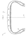
- pneumatic tire 10 includes carcass 12 which extends in a toroidal shape, belt 14 provided at an outside of a crown portion of carcass 12, and tread section 16 provided outside of belt 14 and continues in a toroidal manner between side wall portions.
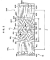
- center area 19 of tread 17 of tread section 16 includes center main grooves 20L and 20R formed symmetrically with respect to tire equator surface CL and extending in the circumferential direction of the tire.
- Shoulder main grooves 22L and 22R extending in the circumferential direction of the tire are formed in the tire width direction outer side of center main grooves 20L and 20R, respectively.
- lug groove 28L connecting center main groove 20L and shoulder main groove 22L, and lug groove 28R connecting center main groove 20R and shoulder main groove 22R are formed in center area 19.
- center land portion 24 is defined by center main grooves 20L and 20R and positioned on tire equator surface CL.
- Second block array 26L is defined by center main groove 20L, shoulder main groove 22L and lug groove 28L.
- Second block array 26R is defined by center main groove 20R, shoulder main groove 22R and lug groove 28R.
- Second block arrays 26L and 26R are each formed by an array of second blocks 30.
- Lug groove 58L connecting shoulder main groove 22L and an end of a ground contact area is formed in tread section 16.
- Shoulder block array 54L in which shoulder blocks 40 are arranged linearly is formed at the tire width direction outer side of shoulder main groove 22L.
- lug groove 58R connecting shoulder main groove 22R and an end of a ground contact area is formed in tread section 16.
- Shoulder block array 54R is formed at the tire width direction outer side of shoulder main groove 22R.
- the outer ends of lug grooves 58L and 58R in the width direction of the tire are positioned further toward the outer side of the tread end in the width direction of the tire.
- the tread end means a ground contact area of a pneumatic tire positioned at a width direction outermost side of the tire, the pneumatic tire being fitted to a standard rim provided in JATMA YEAR BOOK (2002, Standards of The Japan Automobile Tire Manufacturers Association), filled with 100% of air pressure (maximum air pressure) corresponding to the maximum load performance (load indicated in boldface in the internal pressure - load performance table) at an applied size/Ply Rating in JATMA YEAR BOOK, and loaded with the maximum load performance.
- JATMA YEAR BOOK 2002, Standards of The Japan Automobile Tire Manufacturers Association
- 3D sipes 42L are formed in shoulder blocks 40L constituting shoulder block array 54L, and 3D sipes 42R are formed in shoulder blocks 40R constituting shoulder block array 54R.
- 3D sipes 42L and 42R run like a wave in the width direction of the tire and extend in the depth direction of the block (depth direction of the tire) as a plane at the surface of the block and like a wave at an inner portion of the block deeper than the block surface.
- washboard-like block plate portions 44 formed by 3D sipes 42 are arranged in a parallel manner.
- 2D sipes 36L are formed in second blocks 30L constituting second block array 26L.
- 2D sipes 36L extend like a wave substantially in a similar extending direction as the lug groove 28R and extend as a plane with respect to the depth direction of the block (depth direction of the tire).
- shapes and positions of the sipes are the same as those of the block surface in any cross-section along the surface of second blocks 30.
- Second blocks 30R constituting second block array 26R and second blocks 30L are symmetric with respect to tire equator surface CL.
- 2D sipes 36R that are equivalent to 2D sipes 36L are formed in second blocks 30R.
- the sipes formed in shoulder block arrays 54L and 54R are 3D sipes
- the sipes formed in second block arrays 26L and 26R are 2D sipes
- the sipes formed in center land portion 24 are 2D sipes.
- block rigidity is highest at shoulder block arrays 54L and 54R, is lowest at center land portion 24, and is intermediate at second block arrays 26L and 26R.
- center land portion 24 and second block arrays 26L and 26R an adequate edge effect on snow and icy roads is provided by center land portion 24 and second block arrays 26L and 26R, and adequate brake performance and drivability on dry/wet roads are provided by shoulder block arrays 54L and 54R.
- rigidity of blocks 30L and 30R constituting second block arrays 26L and 26R respectively may be the same as that of center land portion 24, or at an intermediate level between those of center land portion 24 and shoulder block 40.
- the sipes formed in center land portion 24 may be 1D sipes (linear sipes) alone, or may be a combination of 1D sipes and 2D sipes.
- the sipes formed in second blocks 30L and 30R may be 1D sipes alone, a combination of 1D sipes and 2D sipes, a combination of 1D sipes and 3D sipes, or a combination of 2D sipes and 3D sipes.
- the sipes formed in shoulder blocks 40R and 40L may be a combination of 1D sipes and 3D sipes or a combination of 2D sipes and 3D sipes.
- a pneumatic tire that has a tread section on which main groove (center main groove) extending in the circumferential direction of the tire is formed on the tire equator surface instead of a center land portion
- main groove center main groove
- adequate performance on snow and icy roads and adequate performance on dry/wet roads can be effectively achieved at the same time, as in the present embodiment, by forming the sipes on the block arrays adjacent to the both sides of the center main groove to be the same as the sipes on center land portion 24.
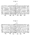
- all of the 2D sipes 63L and 63R formed in the center land portion, 2D sipes 66L and 66R formed in the second block arrays, and 3D sipes 62L and 62R formed in the shoulder block arrays run in a triangular shape, i.e., in a zigzag manner, on the tread surface.
- tread patterns can further be varied.
- 3D sipes 82 formed in the shoulder block arrays extend in a crank shape along a depth direction of the block.
- the rigidity ratio of the shoulder block with respect to those of the center block and the second block may be set larger when needed.
- 3D sipes 92 formed in the shoulder block arrays extend as a plane in the depth direction of the block and then extend in a shape of circular arc, thereby presenting the shape of a roof tile.
- the present inventors conducted several tests on performance on snow and icy roads, performance on dry roads and performance on wet roads for each of the following:
- performance of conventional pneumatic tire 1 was measured in view of performance on snow, performance on wet roads and performance on dry roads, and each performance was referred to as index 100.
- Performance of other pneumatic tires was evaluated and represented by relative indices. Evaluated indices are also shown in Table 1. In Table 1, higher index shows higher performance.
- the pneumatic tire according to the invention is suitable for use as a tire in which performance on snow and icy roads and performance on dry/wet roads are effectively achieved at the same time.
Landscapes
- Engineering & Computer Science (AREA)
- Mechanical Engineering (AREA)
- Tires In General (AREA)
Applications Claiming Priority (2)
| Application Number | Priority Date | Filing Date | Title |
|---|---|---|---|
| JP2004245706 | 2004-08-25 | ||
| PCT/JP2005/014081 WO2006022120A1 (ja) | 2004-08-25 | 2005-08-02 | 空気入りタイヤ |
Publications (3)
| Publication Number | Publication Date |
|---|---|
| EP1787826A1 true EP1787826A1 (de) | 2007-05-23 |
| EP1787826A4 EP1787826A4 (de) | 2008-09-10 |
| EP1787826B1 EP1787826B1 (de) | 2010-06-16 |
Family
ID=35967339
Family Applications (1)
| Application Number | Title | Priority Date | Filing Date |
|---|---|---|---|
| EP05768776A Expired - Lifetime EP1787826B1 (de) | 2004-08-25 | 2005-08-02 | Luftreifen |
Country Status (5)
| Country | Link |
|---|---|
| US (1) | US20080156405A1 (de) |
| EP (1) | EP1787826B1 (de) |
| JP (1) | JP4677408B2 (de) |
| DE (1) | DE602005021891D1 (de) |
| WO (1) | WO2006022120A1 (de) |
Cited By (5)
| Publication number | Priority date | Publication date | Assignee | Title |
|---|---|---|---|---|
| WO2009005565A1 (en) * | 2007-06-27 | 2009-01-08 | Bridgestone Firestone North American Tire, Llc | Tire including segmented sipes |
| EP2199111A2 (de) | 2008-12-22 | 2010-06-23 | Sumtiomo Rubber Industries Ltd | Luftreifen mit Lamellen |
| CN103909787A (zh) * | 2013-01-08 | 2014-07-09 | 住友橡胶工业株式会社 | 充气轮胎 |
| CN104070937A (zh) * | 2013-03-26 | 2014-10-01 | 株式会社普利司通 | 轮胎 |
| WO2018192694A1 (de) * | 2017-04-21 | 2018-10-25 | Continental Reifen Deutschland Gmbh | Fahrzeugluftreifen mit einem feineinschnitt in einem profilblockelement |
Families Citing this family (29)
| Publication number | Priority date | Publication date | Assignee | Title |
|---|---|---|---|---|
| US9521999B2 (en) | 2005-09-13 | 2016-12-20 | Arthrex, Inc. | Fully-threaded bioabsorbable suture anchor |
| JP2007314137A (ja) * | 2006-05-29 | 2007-12-06 | Bridgestone Corp | 空気入りタイヤ |
| US8261789B2 (en) * | 2007-10-25 | 2012-09-11 | Continental Tire North America, Inc. | Tire tread having three different sipe types |
| JP5102711B2 (ja) * | 2008-07-16 | 2012-12-19 | 株式会社ブリヂストン | 空気入りタイヤ |
| USD608724S1 (en) | 2009-03-16 | 2010-01-26 | Trek Bicycle Corporation | Bicycle tire tread |
| JP5603563B2 (ja) * | 2009-04-24 | 2014-10-08 | 株式会社ブリヂストン | タイヤ |
| CN102448745B (zh) * | 2009-05-29 | 2015-02-18 | 倍耐力轮胎股份公司 | 冬季轮胎 |
| JP5404378B2 (ja) * | 2009-12-28 | 2014-01-29 | 株式会社ブリヂストン | 空気入りタイヤ |
| JP5316591B2 (ja) * | 2011-06-08 | 2013-10-16 | 横浜ゴム株式会社 | 空気入りタイヤ |
| JP5440583B2 (ja) * | 2011-10-04 | 2014-03-12 | 横浜ゴム株式会社 | 空気入りタイヤ |
| US9463670B2 (en) | 2011-10-04 | 2016-10-11 | The Yokohama Rubber Co., Ltd. | Pneumatic tire |
| JP5440584B2 (ja) * | 2011-10-04 | 2014-03-12 | 横浜ゴム株式会社 | 空気入りタイヤ |
| JP5923917B2 (ja) * | 2011-10-04 | 2016-05-25 | 横浜ゴム株式会社 | 空気入りタイヤ |
| JP5440590B2 (ja) | 2011-11-14 | 2014-03-12 | 横浜ゴム株式会社 | 空気入りタイヤ |
| JP5948995B2 (ja) * | 2012-03-14 | 2016-07-06 | 横浜ゴム株式会社 | 空気入りタイヤ |
| AU2014227282B2 (en) * | 2013-03-06 | 2016-03-17 | The Yokohama Rubber Co., Ltd. | Pneumatic tire |
| JP5690375B2 (ja) | 2013-06-05 | 2015-03-25 | 株式会社ブリヂストン | タイヤ |
| KR101513362B1 (ko) * | 2013-10-23 | 2015-04-17 | 한국타이어 주식회사 | 스노우 타이어용 커프 구조 |
| JP6330568B2 (ja) | 2014-08-11 | 2018-05-30 | 横浜ゴム株式会社 | 空気入りタイヤ |
| JP6300691B2 (ja) * | 2014-09-29 | 2018-03-28 | 東洋ゴム工業株式会社 | 空気入りタイヤ |
| JP6107843B2 (ja) | 2015-01-22 | 2017-04-05 | 横浜ゴム株式会社 | 空気入りタイヤ |
| JP5983788B2 (ja) * | 2015-01-22 | 2016-09-06 | 横浜ゴム株式会社 | 空気入りタイヤ |
| JP6714985B2 (ja) * | 2015-09-09 | 2020-07-01 | 株式会社ブリヂストン | タイヤ |
| JP6672900B2 (ja) * | 2016-03-04 | 2020-03-25 | 住友ゴム工業株式会社 | 空気入りタイヤ |
| JP7577570B2 (ja) * | 2021-03-01 | 2024-11-05 | 株式会社ブリヂストン | 空気入りタイヤ |
| FI20235512A1 (en) * | 2023-05-08 | 2024-11-09 | Nokian Renkaat Oyj | STUD FOR STUD TIRE |
| JP2025125976A (ja) * | 2024-02-16 | 2025-08-28 | 住友ゴム工業株式会社 | タイヤ |
| US20260061777A1 (en) * | 2024-08-27 | 2026-03-05 | The Goodyear Tire & Rubber Company | Tire tread with tilted sipes |
| USD1116989S1 (en) | 2025-01-31 | 2026-03-10 | The Goodyear Tire & Rubber Company | Tire |
Family Cites Families (11)
| Publication number | Priority date | Publication date | Assignee | Title |
|---|---|---|---|---|
| JP3471503B2 (ja) * | 1995-11-20 | 2003-12-02 | 横浜ゴム株式会社 | 空気入りタイヤ |
| JP4081177B2 (ja) * | 1997-07-07 | 2008-04-23 | 株式会社ブリヂストン | 空気入りタイヤ |
| US6427737B1 (en) * | 1998-04-22 | 2002-08-06 | Bridgestone Corporation | Pneumatic tire having at least four sipes |
| JP2001063322A (ja) * | 1999-08-31 | 2001-03-13 | Bridgestone Corp | 空気入りタイヤ |
| JP3504632B2 (ja) * | 2001-04-27 | 2004-03-08 | 東洋ゴム工業株式会社 | 空気入りタイヤ |
| JP3648179B2 (ja) * | 2001-07-18 | 2005-05-18 | 住友ゴム工業株式会社 | 空気入りタイヤ及びその加硫金型 |
| DE10312488A1 (de) * | 2003-03-20 | 2004-09-30 | Continental Aktiengesellschaft | Fahrzeugreifen, insbesondere Winterreifen mit einem Laufstreifenprofil |
| JP2005041393A (ja) * | 2003-07-24 | 2005-02-17 | Bridgestone Corp | 空気入りタイヤ |
| JP2005153787A (ja) * | 2003-11-27 | 2005-06-16 | Bridgestone Corp | 空気入りタイヤ |
| JP4433804B2 (ja) * | 2004-01-21 | 2010-03-17 | 横浜ゴム株式会社 | 空気入りラジアルタイヤ |
| JP4294532B2 (ja) * | 2004-04-09 | 2009-07-15 | 株式会社ブリヂストン | 空気入りタイヤ |
-
2005
- 2005-08-02 DE DE602005021891T patent/DE602005021891D1/de not_active Expired - Lifetime
- 2005-08-02 WO PCT/JP2005/014081 patent/WO2006022120A1/ja not_active Ceased
- 2005-08-02 JP JP2006531474A patent/JP4677408B2/ja not_active Expired - Fee Related
- 2005-08-02 US US11/661,196 patent/US20080156405A1/en not_active Abandoned
- 2005-08-02 EP EP05768776A patent/EP1787826B1/de not_active Expired - Lifetime
Cited By (12)
| Publication number | Priority date | Publication date | Assignee | Title |
|---|---|---|---|---|
| WO2009005565A1 (en) * | 2007-06-27 | 2009-01-08 | Bridgestone Firestone North American Tire, Llc | Tire including segmented sipes |
| EP2199111A2 (de) | 2008-12-22 | 2010-06-23 | Sumtiomo Rubber Industries Ltd | Luftreifen mit Lamellen |
| EP2199111A3 (de) * | 2008-12-22 | 2013-03-06 | Sumitomo Rubber Industries, Ltd. | Luftreifen mit Lamellen |
| US8578985B2 (en) | 2008-12-22 | 2013-11-12 | Sumitomo Rubber Industries, Ltd. | Pneumatic tire with sipes |
| RU2508204C2 (ru) * | 2008-12-22 | 2014-02-27 | Сумитомо Раббер Индастриз, Лтд. | Пневматическая шина со щелевидными дренажными канавками |
| CN103909787A (zh) * | 2013-01-08 | 2014-07-09 | 住友橡胶工业株式会社 | 充气轮胎 |
| CN103909787B (zh) * | 2013-01-08 | 2017-09-08 | 住友橡胶工业株式会社 | 充气轮胎 |
| CN104070937A (zh) * | 2013-03-26 | 2014-10-01 | 株式会社普利司通 | 轮胎 |
| US9393842B2 (en) | 2013-03-26 | 2016-07-19 | Bridgestone Corporation | Tire |
| CN104070937B (zh) * | 2013-03-26 | 2017-04-12 | 株式会社普利司通 | 轮胎 |
| WO2018192694A1 (de) * | 2017-04-21 | 2018-10-25 | Continental Reifen Deutschland Gmbh | Fahrzeugluftreifen mit einem feineinschnitt in einem profilblockelement |
| CN110520308A (zh) * | 2017-04-21 | 2019-11-29 | 大陆轮胎德国有限公司 | 具有胎纹块单元中的细切入口的车辆充气轮胎 |
Also Published As
| Publication number | Publication date |
|---|---|
| JPWO2006022120A1 (ja) | 2008-05-08 |
| JP4677408B2 (ja) | 2011-04-27 |
| EP1787826B1 (de) | 2010-06-16 |
| WO2006022120A1 (ja) | 2006-03-02 |
| EP1787826A4 (de) | 2008-09-10 |
| DE602005021891D1 (de) | 2010-07-29 |
| US20080156405A1 (en) | 2008-07-03 |
Similar Documents
| Publication | Publication Date | Title |
|---|---|---|
| EP1787826B1 (de) | Luftreifen | |
| CN103832220B (zh) | 充气轮胎 | |
| CA2124608C (en) | Radial pneumatic light truck or automobile tire | |
| US9855801B2 (en) | Pneumatic tire | |
| RU2596390C2 (ru) | Пневматическая шина | |
| US9884519B2 (en) | Pneumatic tire | |
| US9090134B2 (en) | Pneumatic tire | |
| CN110406327B (zh) | 轮胎 | |
| CN107199833B (zh) | 充气轮胎 | |
| US20150151586A1 (en) | Pneumatic Tire | |
| CN108859612B (zh) | 轮胎 | |
| US20160144668A1 (en) | Pneumatic tire | |
| US12515479B2 (en) | Tire | |
| CN113173037B (zh) | 轮胎 | |
| US20120037289A1 (en) | Pneumatic tire | |
| US11845302B2 (en) | Tire | |
| CN108602391A (zh) | 充气轮胎 | |
| AU2009318659A1 (en) | Pneumatic tire | |
| US8746303B2 (en) | Pneumatic tire | |
| US11407256B2 (en) | Tyre | |
| CN105644271A (zh) | 重载充气轮胎 | |
| US9446629B2 (en) | Pneumatic tire | |
| JP4425064B2 (ja) | 空気入りタイヤ | |
| JP4233665B2 (ja) | 空気入りタイヤ | |
| JP2025005864A (ja) | タイヤ |
Legal Events
| Date | Code | Title | Description |
|---|---|---|---|
| PUAI | Public reference made under article 153(3) epc to a published international application that has entered the european phase |
Free format text: ORIGINAL CODE: 0009012 |
|
| 17P | Request for examination filed |
Effective date: 20070316 |
|
| AK | Designated contracting states |
Kind code of ref document: A1 Designated state(s): DE FI FR GB SE |
|
| DAX | Request for extension of the european patent (deleted) | ||
| RBV | Designated contracting states (corrected) |
Designated state(s): DE FI FR GB SE |
|
| A4 | Supplementary search report drawn up and despatched |
Effective date: 20080812 |
|
| 17Q | First examination report despatched |
Effective date: 20081106 |
|
| GRAJ | Information related to disapproval of communication of intention to grant by the applicant or resumption of examination proceedings by the epo deleted |
Free format text: ORIGINAL CODE: EPIDOSDIGR1 |
|
| GRAP | Despatch of communication of intention to grant a patent |
Free format text: ORIGINAL CODE: EPIDOSNIGR1 |
|
| GRAS | Grant fee paid |
Free format text: ORIGINAL CODE: EPIDOSNIGR3 |
|
| GRAA | (expected) grant |
Free format text: ORIGINAL CODE: 0009210 |
|
| AK | Designated contracting states |
Kind code of ref document: B1 Designated state(s): DE FI FR GB SE |
|
| REF | Corresponds to: |
Ref document number: 602005021891 Country of ref document: DE Date of ref document: 20100729 Kind code of ref document: P |
|
| REG | Reference to a national code |
Ref country code: SE Ref legal event code: TRGR |
|
| PLBE | No opposition filed within time limit |
Free format text: ORIGINAL CODE: 0009261 |
|
| STAA | Information on the status of an ep patent application or granted ep patent |
Free format text: STATUS: NO OPPOSITION FILED WITHIN TIME LIMIT |
|
| REG | Reference to a national code |
Ref country code: FR Ref legal event code: ST Effective date: 20110502 |
|
| 26N | No opposition filed |
Effective date: 20110317 |
|
| GBPC | Gb: european patent ceased through non-payment of renewal fee |
Effective date: 20100916 |
|
| REG | Reference to a national code |
Ref country code: DE Ref legal event code: R097 Ref document number: 602005021891 Country of ref document: DE Effective date: 20110316 |
|
| PG25 | Lapsed in a contracting state [announced via postgrant information from national office to epo] |
Ref country code: FR Free format text: LAPSE BECAUSE OF NON-PAYMENT OF DUE FEES Effective date: 20100831 |
|
| PG25 | Lapsed in a contracting state [announced via postgrant information from national office to epo] |
Ref country code: GB Free format text: LAPSE BECAUSE OF NON-PAYMENT OF DUE FEES Effective date: 20100916 |
|
| REG | Reference to a national code |
Ref country code: DE Ref legal event code: R082 Ref document number: 602005021891 Country of ref document: DE Representative=s name: BARDEHLE PAGENBERG PARTNERSCHAFT MBB PATENTANW, DE |
|
| REG | Reference to a national code |
Ref country code: DE Ref legal event code: R081 Ref document number: 602005021891 Country of ref document: DE Owner name: BRIDGESTONE CORPORATION, JP Free format text: FORMER OWNER: BRIDGESTONE CORP., TOKIO/TOKYO, JP Effective date: 20140828 Ref country code: DE Ref legal event code: R082 Ref document number: 602005021891 Country of ref document: DE Representative=s name: BARDEHLE PAGENBERG PARTNERSCHAFT MBB PATENTANW, DE Effective date: 20140828 |
|
| PGFP | Annual fee paid to national office [announced via postgrant information from national office to epo] |
Ref country code: SE Payment date: 20190821 Year of fee payment: 15 Ref country code: FI Payment date: 20190822 Year of fee payment: 15 Ref country code: DE Payment date: 20190822 Year of fee payment: 15 |
|
| REG | Reference to a national code |
Ref country code: DE Ref legal event code: R119 Ref document number: 602005021891 Country of ref document: DE |
|
| REG | Reference to a national code |
Ref country code: FI Ref legal event code: MAE |
|
| REG | Reference to a national code |
Ref country code: SE Ref legal event code: EUG |
|
| PG25 | Lapsed in a contracting state [announced via postgrant information from national office to epo] |
Ref country code: FI Free format text: LAPSE BECAUSE OF NON-PAYMENT OF DUE FEES Effective date: 20200802 |
|
| PG25 | Lapsed in a contracting state [announced via postgrant information from national office to epo] |
Ref country code: SE Free format text: LAPSE BECAUSE OF NON-PAYMENT OF DUE FEES Effective date: 20200803 |
|
| PG25 | Lapsed in a contracting state [announced via postgrant information from national office to epo] |
Ref country code: DE Free format text: LAPSE BECAUSE OF NON-PAYMENT OF DUE FEES Effective date: 20210302 |