EP1787882A1 - Système de frein a commande électromécanique - Google Patents
Système de frein a commande électromécanique Download PDFInfo
- Publication number
- EP1787882A1 EP1787882A1 EP06023839A EP06023839A EP1787882A1 EP 1787882 A1 EP1787882 A1 EP 1787882A1 EP 06023839 A EP06023839 A EP 06023839A EP 06023839 A EP06023839 A EP 06023839A EP 1787882 A1 EP1787882 A1 EP 1787882A1
- Authority
- EP
- European Patent Office
- Prior art keywords
- electro
- parking brake
- brake
- motor
- parking
- Prior art date
- Legal status (The legal status is an assumption and is not a legal conclusion. Google has not performed a legal analysis and makes no representation as to the accuracy of the status listed.)
- Granted
Links
- 230000007257 malfunction Effects 0.000 claims abstract description 22
- 230000005540 biological transmission Effects 0.000 claims description 45
- 230000007246 mechanism Effects 0.000 claims description 42
- 230000008859 change Effects 0.000 claims description 10
- 230000001276 controlling effect Effects 0.000 claims description 9
- 230000001105 regulatory effect Effects 0.000 claims description 6
- 238000006073 displacement reaction Methods 0.000 abstract description 11
- 230000005856 abnormality Effects 0.000 description 15
- 238000000034 method Methods 0.000 description 12
- 230000001174 ascending effect Effects 0.000 description 5
- 239000003638 chemical reducing agent Substances 0.000 description 4
- 230000008569 process Effects 0.000 description 4
- 230000002159 abnormal effect Effects 0.000 description 3
- 238000005299 abrasion Methods 0.000 description 2
- 238000006243 chemical reaction Methods 0.000 description 2
- 230000006866 deterioration Effects 0.000 description 2
- 238000010586 diagram Methods 0.000 description 2
- 238000005265 energy consumption Methods 0.000 description 2
- 230000005484 gravity Effects 0.000 description 2
- 238000012986 modification Methods 0.000 description 2
- 230000004048 modification Effects 0.000 description 2
- 230000009471 action Effects 0.000 description 1
- 238000004891 communication Methods 0.000 description 1
- 238000012790 confirmation Methods 0.000 description 1
- 230000020169 heat generation Effects 0.000 description 1
- 230000002401 inhibitory effect Effects 0.000 description 1
- 238000012544 monitoring process Methods 0.000 description 1
- 230000002093 peripheral effect Effects 0.000 description 1
- 230000009467 reduction Effects 0.000 description 1
- 239000007787 solid Substances 0.000 description 1
Images


Classifications
-
- B—PERFORMING OPERATIONS; TRANSPORTING
- B60—VEHICLES IN GENERAL
- B60T—VEHICLE BRAKE CONTROL SYSTEMS OR PARTS THEREOF; BRAKE CONTROL SYSTEMS OR PARTS THEREOF, IN GENERAL; ARRANGEMENT OF BRAKING ELEMENTS ON VEHICLES IN GENERAL; PORTABLE DEVICES FOR PREVENTING UNWANTED MOVEMENT OF VEHICLES; VEHICLE MODIFICATIONS TO FACILITATE COOLING OF BRAKES
- B60T13/00—Transmitting braking action from initiating means to ultimate brake actuator with power assistance or drive; Brake systems incorporating such transmitting means, e.g. air-pressure brake systems
- B60T13/74—Transmitting braking action from initiating means to ultimate brake actuator with power assistance or drive; Brake systems incorporating such transmitting means, e.g. air-pressure brake systems with electrical assistance or drive
-
- B—PERFORMING OPERATIONS; TRANSPORTING
- B60—VEHICLES IN GENERAL
- B60T—VEHICLE BRAKE CONTROL SYSTEMS OR PARTS THEREOF; BRAKE CONTROL SYSTEMS OR PARTS THEREOF, IN GENERAL; ARRANGEMENT OF BRAKING ELEMENTS ON VEHICLES IN GENERAL; PORTABLE DEVICES FOR PREVENTING UNWANTED MOVEMENT OF VEHICLES; VEHICLE MODIFICATIONS TO FACILITATE COOLING OF BRAKES
- B60T7/00—Brake-action initiating means
- B60T7/12—Brake-action initiating means for automatic initiation; for initiation not subject to will of driver or passenger
-
- F—MECHANICAL ENGINEERING; LIGHTING; HEATING; WEAPONS; BLASTING
- F16—ENGINEERING ELEMENTS AND UNITS; GENERAL MEASURES FOR PRODUCING AND MAINTAINING EFFECTIVE FUNCTIONING OF MACHINES OR INSTALLATIONS; THERMAL INSULATION IN GENERAL
- F16D—COUPLINGS FOR TRANSMITTING ROTATION; CLUTCHES; BRAKES
- F16D65/00—Parts or details
- F16D65/14—Actuating mechanisms for brakes; Means for initiating operation at a predetermined position
- F16D65/16—Actuating mechanisms for brakes; Means for initiating operation at a predetermined position arranged in or on the brake
- F16D65/18—Actuating mechanisms for brakes; Means for initiating operation at a predetermined position arranged in or on the brake adapted for drawing members together, e.g. for disc brakes
-
- F—MECHANICAL ENGINEERING; LIGHTING; HEATING; WEAPONS; BLASTING
- F16—ENGINEERING ELEMENTS AND UNITS; GENERAL MEASURES FOR PRODUCING AND MAINTAINING EFFECTIVE FUNCTIONING OF MACHINES OR INSTALLATIONS; THERMAL INSULATION IN GENERAL
- F16D—COUPLINGS FOR TRANSMITTING ROTATION; CLUTCHES; BRAKES
- F16D66/00—Arrangements for monitoring working conditions, e.g. wear, temperature
- F16D2066/003—Position, angle or speed
-
- F—MECHANICAL ENGINEERING; LIGHTING; HEATING; WEAPONS; BLASTING
- F16—ENGINEERING ELEMENTS AND UNITS; GENERAL MEASURES FOR PRODUCING AND MAINTAINING EFFECTIVE FUNCTIONING OF MACHINES OR INSTALLATIONS; THERMAL INSULATION IN GENERAL
- F16D—COUPLINGS FOR TRANSMITTING ROTATION; CLUTCHES; BRAKES
- F16D2121/00—Type of actuator operation force
- F16D2121/18—Electric or magnetic
- F16D2121/24—Electric or magnetic using motors
-
- F—MECHANICAL ENGINEERING; LIGHTING; HEATING; WEAPONS; BLASTING
- F16—ENGINEERING ELEMENTS AND UNITS; GENERAL MEASURES FOR PRODUCING AND MAINTAINING EFFECTIVE FUNCTIONING OF MACHINES OR INSTALLATIONS; THERMAL INSULATION IN GENERAL
- F16D—COUPLINGS FOR TRANSMITTING ROTATION; CLUTCHES; BRAKES
- F16D2125/00—Components of actuators
- F16D2125/18—Mechanical mechanisms
- F16D2125/20—Mechanical mechanisms converting rotation to linear movement or vice versa
- F16D2125/34—Mechanical mechanisms converting rotation to linear movement or vice versa acting in the direction of the axis of rotation
- F16D2125/40—Screw-and-nut
-
- F—MECHANICAL ENGINEERING; LIGHTING; HEATING; WEAPONS; BLASTING
- F16—ENGINEERING ELEMENTS AND UNITS; GENERAL MEASURES FOR PRODUCING AND MAINTAINING EFFECTIVE FUNCTIONING OF MACHINES OR INSTALLATIONS; THERMAL INSULATION IN GENERAL
- F16D—COUPLINGS FOR TRANSMITTING ROTATION; CLUTCHES; BRAKES
- F16D2125/00—Components of actuators
- F16D2125/18—Mechanical mechanisms
- F16D2125/44—Mechanical mechanisms transmitting rotation
- F16D2125/46—Rotating members in mutual engagement
- F16D2125/50—Rotating members in mutual engagement with parallel non-stationary axes, e.g. planetary gearing
-
- F—MECHANICAL ENGINEERING; LIGHTING; HEATING; WEAPONS; BLASTING
- F16—ENGINEERING ELEMENTS AND UNITS; GENERAL MEASURES FOR PRODUCING AND MAINTAINING EFFECTIVE FUNCTIONING OF MACHINES OR INSTALLATIONS; THERMAL INSULATION IN GENERAL
- F16D—COUPLINGS FOR TRANSMITTING ROTATION; CLUTCHES; BRAKES
- F16D2127/00—Auxiliary mechanisms
- F16D2127/06—Locking mechanisms, e.g. acting on actuators, on release mechanisms or on force transmission mechanisms
-
- F—MECHANICAL ENGINEERING; LIGHTING; HEATING; WEAPONS; BLASTING
- F16—ENGINEERING ELEMENTS AND UNITS; GENERAL MEASURES FOR PRODUCING AND MAINTAINING EFFECTIVE FUNCTIONING OF MACHINES OR INSTALLATIONS; THERMAL INSULATION IN GENERAL
- F16D—COUPLINGS FOR TRANSMITTING ROTATION; CLUTCHES; BRAKES
- F16D2129/00—Type of operation source for auxiliary mechanisms
- F16D2129/06—Electric or magnetic
- F16D2129/08—Electromagnets
Definitions
- the present invention relates to an electro-mechanical brake system and an electro-mechanical brake apparatus used for the electro-mechanical brake system, and more particularly to an electro-mechanical brake system preferably employed for a system provided with a parking brake function and an electro-mechanical brake apparatus used for the electro-mechanical brake system.
- the parking brake can be substituted by setting a transmission to a low speed gear in a vehicle having a manual transmission or setting a transmission to a parking range in a vehicle having an automatic transmission.
- an electro-mechanical parking brake apparatus in which a braking member is actuated by a power generated by a motor, a braking force is generated by a friction force generated between the braking member and a braked member, and a stop state of a vehicle is held by a pad pressing force holding means, a parking brake actuation state is generated after a parking brake actuation switch is operated and an operation of the pressing force holding means and an operation check thereof are finished. Accordingly, a time required until the parking brake actuation state is generated after the parking brake actuation switch is operated becomes longer than a wire type parking brake apparatus. Therefore, there is a possibility that a probability at which the states in the items (1) and (2) are generated becomes higher, and a brake control at a time when the malfunction of the parking brake is generated is necessary.
- An object of the present invention is to provide an electro-mechanical brake system which can keep a stop state even if a malfunction is generated in a parking brake, and an electro-mechanical brake apparatus used for the electro-mechanical brake system.
- Fig. 1 is a system block diagram showing the system structure of the electro-mechanical brake system in accordance with the first embodiment of the present invention.
- a driving force of an engine (EG) 40 is shifted by a transmission (TM) 42, is transmitted to each of front wheels 8a and 8b via a differential gear (DF) 44, and rotationally drives the front wheels 8a and 8b.
- a motor may be employed, or a hybrid system comprising the engine and the motor may be employed.
- the transmission 42 may be constituted by an automatic transmission or a manual transmission. In this case, at a time of applying a second embodiment mentioned below, it is necessary that the transmission 42 employs an electronically controlled automatic transmission provided with an actuator electronically executing a shift operation, an automatic transmission controlling a change of a shift gear by an actuator, or the like.
- an electro-mechanical power steering is provided.
- the electro-mechanical power steering is constituted by a motor 54, and a motor driver 56 driving the motor 54.
- a hydraulic mechanism may be employed in addition to the electro-mechanical mechanism.
- the front wheels 8a and 8b and rear wheels 8c and 8d are respectively provided with disc rotors 7a, 7b, 7c and 7d.
- the disc rotors 7a, 7b, 7c and 7d are respectively rotated together with the front wheels 8a and 8b and the rear wheels 8c and 8d.
- Electro-mechanical brake actuators 6a, 6b, 6c and 6d push the disc rotors 7a, 7b, 7c and 7d so as to slide.
- the electro-mechanical brake actuators 6c and 6d provided in the rear wheel are provided with a parking brake function.
- An amount of displacement of the brake pedal 1 is converted into an electric signal by a stroke sensor 2, and is input to a main controller 3. Further, a parking brake signal output in the case that a parking brake operation switch 9 is operated is input to the main controller 3.
- a road surface slope sensor 60 detects an angle of incline of a road surface at which the vehicle is positioned, and inputs a detected road surface slope signal to the main controller 3. In this case, the road surface slope sensor 60 is used in a second embodiment and a third embodiment which are mentioned below, and is not essential for the first embodiment.
- the main controller 3 generally controls a braking force of each of four wheels on the basis of an electric signal from the stroke sensor 2, and the rear wheel electro-mechanical brake actuators 6c and 6d control the parking brake function on the basis of a parking brake signal from the parking brake operation switch 9.
- Electro-mechanical brake controllers 4a, 4b, 4c and 4d control electro-mechanical brakes of respective wheels on the basis of an electric signal output from the main controller 3.
- Drivers 5a, 5b, 5c and 5d input electric current to motors of the electro-mechanical brake actuators 6a, 6b, 6c and 6d of the respective wheel on the basis of the electric signals output from the electro-mechanical brake controllers 4a, 4b, 4c and 4d, actuate the motor, actuate solenoids provided in the electro-mechanical brake actuators 6c and 6d of the rear wheels, and actuate a parking brake function.
- An electric power of a battery (BA) 24 is supplied to the main controller 3, is supplied to the motors of the electro-mechanical brake actuators 6a, 6b, 6c and 6d via the drivers 5a, 5b, 5c and 5d, and is supplied to the motor 54 via the solenoids of the electro-mechanical brake actuators 6c and 6d, and the motor driver 56.
- BA battery
- Fig. 2 is a cross sectional view of a main portion and shows a structure of the electro-mechanical brake actuator used in the electro-mechanical brake system in accordance with the first embodiment of the present invention.
- the same reference numerals as those in Fig. 1 indicate the same parts.
- the electro-mechanical brake actuator 6 shown in Fig. 2 corresponds to a structure of the electro-mechanical brake actuators 6c and 6d of the rear wheels having the parking brake function.
- the electro-mechanical brake actuators 6a and 6b of the front wheels is structured by removing the parking brake function from the electro-mechanical brake actuator 6 shown in Fig. 2.
- the motor portion of the electro-mechanical brake actuator 6 is constituted by a motor coil 11 fixed to an inner peripheral side of a motor stator 29, a motor rotor 10 rotating in accordance with a change of magnetic field of the motor coil 11, a magnet 12 fixed to the motor rotor 10, and a resolver 18 for detecting a rotational displacement of the motor rotor 10.
- An electric current from the motor driver 5 controlled by the electro-mechanical brake controller 4 is input to the motor coil 11, changes a magnetic field generated by the motor coil 11, and rotates the motor rotor 10.
- the resolver 18 is used for controlling the rotation of the motor, and is used for measuring the displacement of the motor.
- a displacement information of the motor detected by the resolver 18 is input to the main controller 3.
- a rotating speed of the motor rotor 10 of the motor is decelerated by a speed reducer 13, and a rotating torque of the motor rotor 10 is amplified so as to be transmitted to a rotation direct acting converting mechanism.
- the rotation direct acting converting mechanism is structured such as to convert a rotating motion decelerated by the speed reducer 13 to the direct acting motion, and is constituted by a ball screw 14, and a piston 16 directly operated by a ball screw rod 15.
- a rotational motion of the ball screw 14 is converted into a direct action by the ball screw rod 15, and the piston 16 fixed to the ball screw rod 15 executes a direct acting motion.
- the ball screw 14 corresponding to the rotation direct acting converting mechanism can use the other mechanism such as a ball lamp or the like.
- Brake pads 17a and 17b corresponding to a braking member are respectively fixed to support members 28a and 28b.
- the brake pad 17b is fixed to the piston 16, and is pressed to a disc rotor 7 corresponding to a braked member in the case that the piston 16 is moved in a leftward direction in the drawings. Pressing forces of the brake pads 17a and 17b are measured by a pressing force sensor 19, and are input to the main controller 3.
- An electric current flowing through the motor coil 11 is measured by a motor current sensor 23 and is input to the main controller 3.
- the parking brake mechanism is constituted by a latch 21 for constraining a rotating motion of the motor rotor 10, and a solenoid 20 for driving the latch 21.
- the parking brake mechanism is provided in the electro-mechanical brake actuators 6c and 6d for the rear wheels, and are not provided in the electro-mechanical brake actuators 6a and 6b for the front wheels.
- a description will be given later of a structure and an operation of the parking brake mechanism with reference to Fig. 3.
- the main controller 3 calculates a necessary braking force on the basis of a pedal applying amount of a driver or the like, and generates a pad pressing force instruction on the basis of the calculated braking force.
- the pad pressing force instruction is transmitted to the electro-mechanical brake controller 4 via a controller area network (CAN) communication.
- the electro-mechanical brake controller 4 calculates a deviation between the pad pressing force instruction and an actual pressing force measured by the pressing force sensor 19, and generates a motor current instruction signal necessary for reducing the pressing force deviation.
- the motor driver 5 applies the current corresponding to the motor current instruction signal to the motor coil 11.
- the speed reducer 13 is rotated together with the motor rotor 10 so as to actuate the ball screw 14.
- the piston 16 executes the direct acting motion on the basis of the actuation of the ball screw 14, and the brake pad 17 is pressed to the disc rotor 7 or disconnected from the disc rotor 7. In the case that the brake pad 17 is pressed to the disc rotor 7, the brake pad 17 is deformed, and the pressing force is generated.
- the motor corresponding to a drive source of the electro-mechanical brake apparatus in accordance with the present embodiment is a brushless motor constituted by a motor stator 29, a motor coil 11, a motor rotor 10, magnet 12 fixed to the motor rotor 10 and a bearing.
- the brushless motor is controlled by the motor driver 5 by using a measured value of a resolver 18 for detecting the rotational displacement of the motor rotor 10, and a measured value of the motor current sensor 23 measuring a value of the electric current flowing through the motor coil 11.
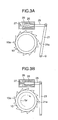
- Fig. 3 is a side elevational view showing a structure of the parking brake mechanism used in the electro-mechanical brake system in accordance with a first embodiment of the present invention.
- Fig. 3A shows a canceled state of the parking brake
- Fig. 3B shows an ON state of the parking brake.
- the same reference numerals as those in Fig. 2 denote the same parts.
- the parking brake mechanism of the present embodiment is constituted by the motor rotor 10 provided with a plurality of latch portions 10a in an outer periphery, a latch 21a constraining a rotation of the motor rotor by locking a latch portion 10a of the motor rotor 10, and the solenoid 20 for driving the latch 21a.
- the latch 21a is provided in the latch rod 21.
- a link mechanism is formed by the latch rod 21 and the solenoid rod 25.
- One end of the latch rod 21 can be rotated around a supporting point O.
- the other end of the latch rod 21 is rotatably engaged with one end of the solenoid rod 25.
- the other end of the solenoid rod 25 is actuated by the solenoid 20.
- the solenoid 20 is schematically structured by a solenoid coil 26, a solenoid spring 27 and the solenoid rod 25.
- the solenoid rod 25 comes to a state of being pressed out by an energizing force of the solenoid spring 27, however, if the electric current is applied to the solenoid coil 26, the solenoid rod 25 is sucked by a magnetic field generated by the solenoid coil 26, and the solenoid spring 27 is compressed.
- Fig. 3A shows a state in which the latch 21 is not engaged with a ratchet of the motor rotor 10, that is, a state at a time of canceling the parking brake.
- the motor rotor 10 can freely rotate.
- Fig. 3B shows a parking brake operating state in which the latch 21 is engaged with the pawl 10a of the motor rotor 10 and the motion of the motor rotor 10 is constrained.
- a clockwise direction is set to a piston backward moving direction (a brake canceling direction)
- a counterclockwise direction is set to a piston forward moving direction (a pad pressing force increasing direction).
- Trf a reaction force of the pressing force
- the latch 21 receives the force in a direction of an arrow Trf from the pawl portion 10a of the motor rotor 10. Since a friction force is generated between the latch 21 and the pawl portion 10a of the motor rotor 10 on the basis of the force, the solenoid rod 25 is not pushed out by an energizing force of the solenoid spring 27 even if the electric current is not applied to the solenoid coil 26. accordingly, it is possible to maintain a state in which the motor rotor 10 is constrained, that is, the parking brake operating state.
- Fig. 4 is a flow chart showing a control contents of the parking brake mechanism used in an electro-mechanical brake system in accordance with a first embodiment of the present invention.
- the control of the present embodiment is executed by the main controller 3. In this case, it is possible to execute by the electro-mechanical brake controller 4.
- the driver operates the parking brake operating switch 9, whereby a parking brake actuation instruction is input to the main controller 3.
- the controller 3 generates a braking force capable of securely holding the vehicle stop by the electro-mechanical brakes 6a and 6b in the front wheels, and generates a braking force capable of securing the vehicle stop by the electro-mechanical brakes 6c and 6d in the rear wheels, in a step s15.
- the controller 3 actuates the parking brakes in the electro-mechanical brakes 6c and 6d in the rear wheels by applying the solenoid 20 shown in Fig. 3.
- the controller 3 executes a parking brake actuation confirmation in a step s25, and judges whether or not the parking brake is abnormal in a step s30.
- Fig. 5 is an explanatory view of the judging method of the parking brake abnormality in the electro-mechanical brake system in accordance with the first embodiment of the present invention.
- Fig. 5A shows a motor current applied to the motors of the electro-mechanical brakes 6c and 6d
- Fig. 5B shows a motor displacement of the motors of the electro-mechanical brakes 6c and 6d
- Fig. 5C shows a pressing force of the motors of the electro-mechanical brakes 6c and 6d.
- Each of these drawing shows a time history by setting a horizontal axis to a time.
- solid lines B1 and C1 show the time history at a time when the parking brake is normal
- broken lines B2 and C2 show the time history at a time when the parking brake is abnormal.
- a state in which the drive of the latch 21 by the solenoid 20 is finished is established at a time t1. If the controller 3 reduces the motor current step by step as shown in Fig. 5A, for confirming the parking brake actuation, from the time t1, the motor rotor 10 is exposed to the torque caused by the reaction force of the pad pressing force. Therefore, the motor rotor 10 is rotated in a direction in which the pressing force is lowered.
- the latch 21a and the ratchet are normal, the latch 21a is engaged with the pawl portion 10a finally even in the case that the motor current is reduced as shown in Fig. 5A, so that the rotation of the motor rotor 10 stops as sown by a solid line B1 in Fig. 5B.
- the motor displacement can be detected by the resolver 18 shown in Fig. 2.
- the controller 3 starts reducing the motor current, and determines a failure of the parking brake actuation in the case that the motor is rotated at a rated amount or more.
- the controller 3 cuts the motor current at a time t2 as shown in Fig. 5A, and cuts the current application to the solenoid coil 26. Thereafter, the controller 3 monitors the motor displacement for a time T, confirms that the motor displacement is not change, and thereafter generates a signal of the parking brake actuation end at a time t3. Accordingly, even in the case that the latch catches on an unstable place such as a top portion of the pawl or the like and the latch comes off by an impact generated at a moment of cutting the electric current of the motor and the solenoid coil, it is possible to recognize as a failure of the parking brake actuation.
- the controller 3 appropriately applies an electric voltage to the motor coil and the solenoid coil in such a manner as to prevent the control of the electro-mechanical brake from being greatly affected, and detects the applied current to the solenoid and the applied current to the motor coil by ampere meters 22 and 23 shown in Fig. 2.
- the abnormality of the parking brake can be determined by assuming that there is generated a power mechanism failure such as disconnection of the motor coil or the solenoid coil or the like.
- a power mechanism failure such as disconnection of the motor coil or the solenoid coil or the like.
- step s30 in the case that the abnormality does not exist in the judgment of the step s30, the step goes to a step s35, and in the case that the abnormality exist, the step goes to a step s50.
- the controller 3 cancels the braking force of the front wheel in the step s35, and monitors the parking brake pressing force of the rear wheel by the pressing force sensor in a step s40.
- the braking force of the front wheel is canceled for the purpose of inhibiting an energy consumption continuously keeping applying the electric current to the motor in correspondence to the braking, and preventing the motor coil from being generated.
- a step s45 the controller 3 judges whether or not the abnormality exists in the pressing force of the rear wheel. In the case that the abnormality does not exist, the controller 3 keeps monitoring the pressing force in the step s40, and in the case that the abnormality exist, the step goes to a step s50.
- step s30 if the controller 3 determines that the abnormality exists in any one of the right and left parking brakes, the controller 3 increases the braking force of the normal parking brake in the step s50 so as to again apply the electric current to the solenoid 26 and actuates the parking brake in a step s55.
- the braking force of the normal parking brake is set to a value corresponding to a total value of the pressing forces generated by the respective parking brakes in the case that both of the parking brakes of the right and left wheels are normal.
- the parking brake is actuated without regarding to the limit.
- the structure is made such that the latch 21 is again actuated after increasing the pressing force at about an interval between the pawl and the pawl of the motor rotor 10 in the case that it is determined that the parking brake actuation is unsuccessful.
- the controller 3 After executing the step s55, the controller 3 outputs the alarm indicating the parking brake failure to the driver, in a step s60.
- the step counts a frequency of the matter that the latch is again actuated by determining the failure of the parking brake actuation, and determines the failure of the parking brake function in the case that the frequency reaches a prescribed frequency C. Accordingly, it is possible to avoid a state in which the pressing force is infinitely increased so as to actuate the latch. In this case, in the case that the value of the prescribed frequency C is set to zero, an operation of increasing the pressing force so as to again actuate the latch is not executed. This means that in the case that the pressing force is lowered at the prescribed amount or more between the time t1 and the time t2 or between the time t2 and the time t3 in Fig. 5, the failure of the parking brake function is immediately determined.
- the present embodiment even in the case that the failure is generated in the parking brake function, in the vehicle in which the electro-mechanical brake is mounted, it is possible to keep the vehicle stop state and it is possible to improve a safety, even in the case that the failure of the parking brake is identified by securing the braking force by the brake apparatus having no parking brake function, and thereafter making the pad pressing force of the normal parking brake equal to or larger than the pad pressing force at a time of the normal parking brake, thereby generating the parking brake actuation instruction in the state in which the driver cancels the normal brake, or even in the case that the failure of the parking brake is identified after outputting the parking brake actuation instruction in the state in which the driver applies the normal brake, and canceling the normal brake.
- a system structure of the electro-mechanical brake system in accordance with the present embodiment is the same as that shown in Fig. 1.
- the road surface slope sensor 60 and the transmission 42 shown in Fig. 1 constitute the electronically controlled automatic transmission provided with the actuator electronically executing the shift operation or the automatic MT controlling the change of the shift gear by the actuator.
- the structures of the electro-mechanical brake actuators 6a, 6b, 6c and 6d used in the electro-mechanical brake system in accordance with the present embodiment are the same as those shown in Fig. 2.
- the structure and the operation of the parking brake mechanism used in the electro-mechanical brake system in accordance with the present embodiment are the same as those shown in Fig. 3.
- Fig. 6 is a flow chart showing an operation of the electro-mechanical brake system in accordance with the second embodiment of the present invention.
- the same step numbers as those in Fig. 4 indicate the same processes.
- the transmission which can be actuated without being constrained by the operation of the driver, the electronically controlled automatic transmission provided with the actuator electronically executing the shift operation, or the automatic MT controlling the change of the shift gear by the actuator.
- the structure has the road surface slope sensor 60 detecting the state of the road surface slope. Further, the structure is made such as to execute the control process for securing the safety by utilizing the transmission in the case that the failure of the parking brake is identified.
- the controller 3 judges in a step s72. whether or not the road surface is an ascending slope with respect to the vehicle; on the basis of the output of the road surface slope sensor 60.
- the controller 3 in the case that it is determined that the road surface is the ascending slope with respect to the vehicle, the controller 3 generates in a step s74 an instruction of setting the gear of the transmission 42 shown in Fig. 1 to a low speed forward moving gear, and controls the actuator of the transmission 42 so as to set to the low speed forward moving gear.
- the controller 3 in the case of determining that the road surface is not the ascending slope, the controller 3 generates in a step s76 an instruction of setting the gear of the transmission 42 shown in Fig. 1 to a reverse gear, and controls the actuator of the transmission 42 so as to set to the low speed forward moving gear.
- the controller 3 After the end of the steps s74 and s76, the controller 3 increases the braking force of the normal parking brake in a step s50, and executes the parking brake actuation in a step s55. Accordingly, it is possible to securely hold the vehicle stop state even on the slope road, and it is possible to secure the safety.
- a system structure of the electro-mechanical brake system in accordance with the present embodiment is the same as that shown in Fig. 1.
- the road surface slope sensor 60 and the transmission 42 shown in Fig. 1 constitute the electronically controlled automatic transmission provided with the actuator electronically executing the shift operation or the automatic MT controlling the change of the shift gear by the actuator, and the steering wheel 50 is provided so as to control the operating direction of the vehicle body.
- the structures of the electro-mechanical brake actuators 6a, 6b, 6c and 6d used in the electro-mechanical brake system in accordance with the present embodiment are the same as those shown in Fig. 2. Further, the structure and the operation of the parking brake mechanism used in the electro-mechanical brake system in accordance with the present embodiment are the same as those shown in Fig. 3.
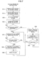
- Fig. 7 is a flow chart showing an operation of the electro-mechanical brake system in accordance with the third embodiment of the present invention.
- the same step numbers as those in Fig. 4 indicate the same processes.
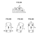
- Fig. 8 is an explanatory view of a steering operation in the electro-mechanical brake system in accordance with the third embodiment of the present invention.
- the transmission which can be actuated without being constrained by the operation of the driver, the electronically controlled automatic transmission provided with the actuator electronically executing the shift operation, or the automatic MT controlling the change of the shift gear by the actuator.
- the structure has the road surface slope sensor 60 detecting the state of the road surface slope.
- the structure has the steering wheel 50 capable of controlling the operating direction of the vehicle body. Further, the structure is made such as to execute the control process for securing the safety by utilizing the transmission in the case that the failure of the parking brake is identified.
- the controller 3 In the case that the step determines in the step s30 in Fig. 7 that the abnormality exists in the parking brake, the controller 3 generated the low speed gear instruction in the step s70. In the case of the automatic transmission, it is possible to set to the parking range.
- the contents of the step s70 is the same control contents as those of the steps s72, s74 and s76 in Fig. 6.
- the controller 3 judges whether or not the slope of the road surface is a steep slope equal to or more than a prescribed value, on the basis of the road surface slope sensor 60. If it is determined that the slope is the steep slope, the controller 3 generates in a step s85 an instruction of operating the steering wheel. It is possible to increase the friction force between the road surface and the wheel so as to more stably hold the vehicle stop state, by operating the steering wheel.
- the controller 3 After the end of the step s85, the controller 3 increases the braking force of the normal parking brake in the step s50, and executes the parking brake actuation in the step s55. Accordingly, it is possible to securely hold the vehicle stop state even on the slope road, and it is possible to secure the safety.
- a description will be given of an operation instruction generating method of the steering wheel by using Fig 8.
- a description will be given by exemplifying the case that the parking brake function of the right rear wheel 8c shown in Fig. 8B is failed on the ascending slope as shown in Fig. 8A, and the vehicle stop state is held only by the parking brake.
- a slope road slope direction component Fg of gravity is applied to a center of gravity of the vehicle body in the ascending slope. Accordingly, a moment (shown by a broken line in the drawing) in a clockwise direction is generated around the left rear wheel 8c braked by the parking brake. In the case that the incline of the slope is steep, the vehicle body is inclined as shown in Fig. 8C on the basis of this moment.
- the friction force in the left forward direction is generated between the front wheel and the road surface by rotating the steering wheel of the front wheel in the right direction and inclining the front wheel in the right direction as shown in Fig.
Landscapes
- Engineering & Computer Science (AREA)
- Mechanical Engineering (AREA)
- Transportation (AREA)
- General Engineering & Computer Science (AREA)
- Regulating Braking Force (AREA)
- Valves And Accessory Devices For Braking Systems (AREA)
- Braking Systems And Boosters (AREA)
- Steering Control In Accordance With Driving Conditions (AREA)
- Control Of Transmission Device (AREA)
Applications Claiming Priority (1)
| Application Number | Priority Date | Filing Date | Title |
|---|---|---|---|
| JP2005331863A JP4912670B2 (ja) | 2005-11-16 | 2005-11-16 | 電動ブレーキシステム |
Publications (2)
| Publication Number | Publication Date |
|---|---|
| EP1787882A1 true EP1787882A1 (fr) | 2007-05-23 |
| EP1787882B1 EP1787882B1 (fr) | 2010-01-27 |
Family
ID=37745982
Family Applications (1)
| Application Number | Title | Priority Date | Filing Date |
|---|---|---|---|
| EP06023839A Not-in-force EP1787882B1 (fr) | 2005-11-16 | 2006-11-16 | Système de frein a commande électromécanique |
Country Status (4)
| Country | Link |
|---|---|
| US (1) | US7850255B2 (fr) |
| EP (1) | EP1787882B1 (fr) |
| JP (1) | JP4912670B2 (fr) |
| DE (1) | DE602006012000D1 (fr) |
Cited By (8)
| Publication number | Priority date | Publication date | Assignee | Title |
|---|---|---|---|---|
| WO2009030726A1 (fr) * | 2007-09-05 | 2009-03-12 | Continental Teves Ag & Co. Ohg | Frein de stationnement à commande électromécanique pour véhicules automobiles et procédé de commande de celui-ci |
| WO2010147323A3 (fr) * | 2009-06-19 | 2011-03-24 | Nam Sang In | Dispositif de retenue de force de freinage pour frein de véhicule |
| KR101118873B1 (ko) * | 2009-06-19 | 2012-03-14 | 남상인 | 자동차 브레이크의 제동력 유지장치 |
| EP2842823A4 (fr) * | 2012-04-24 | 2016-06-22 | Ntn Toyo Bearing Co Ltd | Frein de stationnement électrique |
| EP2913238A4 (fr) * | 2012-10-25 | 2016-09-07 | Ntn Toyo Bearing Co Ltd | Actionneur de frein électrique comprenant une fonction de stationnement |
| EP3318457A4 (fr) * | 2015-07-02 | 2019-03-06 | Mitsubishi Jidosha Kogyo Kabushiki Kaisha | Dispositif de frein électromécanique |
| EP4124527A1 (fr) * | 2021-07-27 | 2023-02-01 | Nabtesco Corporation | Dispositif de freinage, procédé de détermination de fonctionnement anormal et programme de détermination de fonctionnement anormal |
| WO2024114870A1 (fr) * | 2022-12-01 | 2024-06-06 | Continental Automotive Technologies GmbH | Système de freinage électromécanique pour un véhicule automobile avec limitation du couple de lacet |
Families Citing this family (41)
| Publication number | Priority date | Publication date | Assignee | Title |
|---|---|---|---|---|
| JP4333755B2 (ja) * | 2007-03-05 | 2009-09-16 | トヨタ自動車株式会社 | 車両パーキングシステム |
| KR20080111872A (ko) * | 2007-06-20 | 2008-12-24 | 현대모비스 주식회사 | 단일 모터형 전자제어식 웨지브레이크 장치 |
| KR100879890B1 (ko) * | 2007-06-25 | 2009-01-22 | 현대모비스 주식회사 | 솔레노이드를 이용한 부가 기능 구현 타입 단일 모터 전자 웨지 브레이크 시스템 |
| EP2214944B1 (fr) * | 2007-10-24 | 2011-08-31 | Continental Teves AG & Co. oHG | Frein de stationnement et procédé de fonctionnement |
| JP5057164B2 (ja) * | 2008-08-29 | 2012-10-24 | 日立オートモティブシステムズ株式会社 | 電動ディスクブレーキ |
| DE102010003232A1 (de) * | 2009-04-06 | 2010-10-07 | Continental Teves Ag & Co. Ohg | Verfahren zum Betreiben einer Bremsanlage, Bremsanlage und Kraftfahrzeug |
| EP2397384A1 (fr) * | 2010-06-18 | 2011-12-21 | BT Products AB | Agencement et procédé pour détecter une défaillance d'un frein électromécanique |
| DE102010042170A1 (de) * | 2010-10-07 | 2012-04-12 | Honeywell Bremsbelag Gmbh | Messsystem für Eigenfrequenzmessungen an Scheibenbremsbelägen |
| KR101252768B1 (ko) * | 2010-11-22 | 2013-04-09 | 주식회사 현대케피코 | 차량 브레이크 시스템 및 제어 방법 |
| KR101351347B1 (ko) * | 2012-05-25 | 2014-01-15 | 주식회사 만도 | 전자식 주차 브레이크 시스템 및 그 주차 브레이크 스위치의 고장 표시 방법 |
| JP6289855B2 (ja) * | 2013-10-10 | 2018-03-07 | Ntn株式会社 | パーキング機能付き電動ブレーキ装置 |
| JP6260238B2 (ja) * | 2013-12-05 | 2018-01-17 | 株式会社アドヴィックス | 車両の電動制動装置 |
| JP6164071B2 (ja) * | 2013-12-05 | 2017-07-19 | 株式会社アドヴィックス | 車両の電動制動装置 |
| JP6278179B2 (ja) * | 2013-12-05 | 2018-02-14 | 株式会社アドヴィックス | 車両の電動制動装置 |
| KR101574932B1 (ko) * | 2014-09-25 | 2015-12-08 | 현대모비스 주식회사 | 전자식 주차 브레이크의 제어 방법 |
| WO2016047481A1 (fr) * | 2014-09-25 | 2016-03-31 | Ntn株式会社 | Système de frein électrique |
| JP6584877B2 (ja) * | 2014-09-25 | 2019-10-02 | Ntn株式会社 | 電動ブレーキシステム |
| JP6150080B2 (ja) * | 2015-02-25 | 2017-06-21 | 株式会社アドヴィックス | 車両の電動制動装置 |
| JP6156428B2 (ja) * | 2015-03-31 | 2017-07-05 | 株式会社アドヴィックス | 車両の制動力保持装置及び車両の電動制動装置 |
| US10160434B2 (en) * | 2015-05-22 | 2018-12-25 | Robert Bosch Gmbh | Brake device for a motor vehicle and method for the detection of damage to the brake device |
| KR101776496B1 (ko) * | 2016-05-09 | 2017-09-19 | 현대자동차주식회사 | 모터 특성 변화를 감지하는 전동식 브레이크 |
| US10507816B2 (en) * | 2016-08-30 | 2019-12-17 | GM Global Technology Operations LLC | Brake-by-wire system |
| US9995390B2 (en) | 2016-11-03 | 2018-06-12 | Ford Global Technologies, Llc | Brake mechanism for hybrid vehicle engine |
| JP6569644B2 (ja) * | 2016-11-07 | 2019-09-04 | 株式会社アドヴィックス | 車両の電動制動装置 |
| DE102016222045A1 (de) * | 2016-11-10 | 2018-05-17 | Robert Bosch Gmbh | Verfahren und Vorrichtung zum Betreiben einer Bremsanlage eines Kraftfahrzeugs, Bremsanlage |
| JP7040287B2 (ja) * | 2018-05-25 | 2022-03-23 | トヨタ自動車株式会社 | 車両用ブレーキ装置 |
| JP7149212B2 (ja) * | 2019-03-26 | 2022-10-06 | 日立Astemo株式会社 | 電動ブレーキ装置 |
| US12115957B2 (en) * | 2019-04-22 | 2024-10-15 | Hitachi Astemo, Ltd. | Control apparatus |
| JP2021020485A (ja) * | 2019-07-24 | 2021-02-18 | トヨタ自動車株式会社 | 車両の制御装置 |
| CN111114631A (zh) * | 2019-12-27 | 2020-05-08 | 珠海广通汽车有限公司 | 油泵电机的控制方法、控制装置、存储介质和处理器 |
| KR102791266B1 (ko) * | 2020-06-30 | 2025-04-09 | 현대자동차주식회사 | 차량 제어 장치, 시스템 및 방법 |
| CN113264142B (zh) * | 2021-05-28 | 2022-11-11 | 惠州市上理潮玩实业有限公司 | 一种基于木质玩具车的安全保护装置 |
| KR102603347B1 (ko) * | 2021-06-11 | 2023-11-17 | 현대모비스 주식회사 | 전자식 주차 브레이크 제어장치 및 방법 |
| US12145551B2 (en) * | 2021-11-17 | 2024-11-19 | Zf Active Safety Gmbh | Actuator assembly for a vehicle brake and method for activating an actuator assembly for a vehicle brake |
| CN116803781A (zh) * | 2022-03-16 | 2023-09-26 | 六和机械股份有限公司 | 一种车辆电子驻车装置 |
| TWI826958B (zh) * | 2022-03-16 | 2023-12-21 | 六和機械股份有限公司 | 車輛電子駐車裝置 |
| CN115158279B (zh) * | 2022-09-07 | 2022-12-06 | 万向钱潮股份公司 | 电子驻车辅助控制方法及冗余控制系统 |
| WO2024166999A1 (fr) * | 2023-02-10 | 2024-08-15 | 株式会社アドヴィックス | Dispositif de commande de véhicule |
| US12606130B2 (en) * | 2023-06-01 | 2026-04-21 | ZF Active Safety US Inc. | Electromechanical brake for vehicle |
| DE102023205887A1 (de) * | 2023-06-22 | 2024-12-24 | Robert Bosch Gesellschaft mit beschränkter Haftung | Verfahren zum Prüfen einer Funktionsfähigkeit einer elektromechanischen Radbremseinrichtung eines Kraftfahrzeugs, Radbremseinrichtung, Bremssystem |
| DE102023129608A1 (de) * | 2023-10-26 | 2025-04-30 | Svm Schultz Verwaltungs-Gmbh & Co. Kg | Elektromagnet und Verriegelungsanordnung mit Elektromagnet und federvorgespanntem Rastmittel |
Citations (4)
| Publication number | Priority date | Publication date | Assignee | Title |
|---|---|---|---|---|
| EP0924128A1 (fr) * | 1997-12-16 | 1999-06-23 | Toyota Jidosha Kabushiki Kaisha | Procédé et dispositif pour diagnostiquer un frein à action éléctrique sans opérer à main l'élément de frein |
| EP0945322A2 (fr) | 1998-03-26 | 1999-09-29 | Toyota Jidosha Kabushiki Kaisha | Dispositif de freinage électrique de stationnement muni d'un dispositif de changement de force de freinage opérationnel lorsque l'interrupteur d'alimentation en puissance est fermé |
| US6702405B1 (en) * | 1998-03-31 | 2004-03-09 | Continental Teves Ag & Co., Ohg | Electric parking brake |
| EP1686029A1 (fr) * | 2005-01-27 | 2006-08-02 | Hitachi, Ltd. | Système de freinage électrique et unité de commande du système de freinage électrique |
Family Cites Families (10)
| Publication number | Priority date | Publication date | Assignee | Title |
|---|---|---|---|---|
| JPS63189874A (ja) * | 1987-01-31 | 1988-08-05 | Mita Ind Co Ltd | 光学系移動式の複写機 |
| JPS63268941A (ja) * | 1987-04-24 | 1988-11-07 | Fuji Heavy Ind Ltd | エンジンの排気ブレ−キ制御装置 |
| JP3490860B2 (ja) * | 1997-03-25 | 2004-01-26 | 三洋電機株式会社 | 車両の制動制御装置 |
| JP4668380B2 (ja) | 2000-01-21 | 2011-04-13 | 富士重工業株式会社 | 電子制御ブレーキシステム |
| DE10233673A1 (de) * | 2001-07-31 | 2003-03-20 | Tokico Ltd | Elektrische Bremsvorrichtung |
| JP2003083373A (ja) * | 2001-09-07 | 2003-03-19 | Akebono Brake Ind Co Ltd | 電動ブレーキ制御方法 |
| JP4214764B2 (ja) * | 2002-11-11 | 2009-01-28 | 株式会社アドヴィックス | 電動パーキングブレーキ装置 |
| JP2004314756A (ja) * | 2003-04-15 | 2004-11-11 | Asmo Co Ltd | 電動駐車ブレーキシステム |
| JP4239162B2 (ja) * | 2003-06-30 | 2009-03-18 | 株式会社日立製作所 | 電動ブレーキ装置 |
| US7540571B2 (en) * | 2004-05-19 | 2009-06-02 | Hitachi, Ltd. | Motor-driven disk brake system |
-
2005
- 2005-11-16 JP JP2005331863A patent/JP4912670B2/ja not_active Expired - Fee Related
-
2006
- 2006-11-15 US US11/599,489 patent/US7850255B2/en not_active Expired - Fee Related
- 2006-11-16 EP EP06023839A patent/EP1787882B1/fr not_active Not-in-force
- 2006-11-16 DE DE602006012000T patent/DE602006012000D1/de active Active
Patent Citations (4)
| Publication number | Priority date | Publication date | Assignee | Title |
|---|---|---|---|---|
| EP0924128A1 (fr) * | 1997-12-16 | 1999-06-23 | Toyota Jidosha Kabushiki Kaisha | Procédé et dispositif pour diagnostiquer un frein à action éléctrique sans opérer à main l'élément de frein |
| EP0945322A2 (fr) | 1998-03-26 | 1999-09-29 | Toyota Jidosha Kabushiki Kaisha | Dispositif de freinage électrique de stationnement muni d'un dispositif de changement de force de freinage opérationnel lorsque l'interrupteur d'alimentation en puissance est fermé |
| US6702405B1 (en) * | 1998-03-31 | 2004-03-09 | Continental Teves Ag & Co., Ohg | Electric parking brake |
| EP1686029A1 (fr) * | 2005-01-27 | 2006-08-02 | Hitachi, Ltd. | Système de freinage électrique et unité de commande du système de freinage électrique |
Cited By (11)
| Publication number | Priority date | Publication date | Assignee | Title |
|---|---|---|---|---|
| WO2009030726A1 (fr) * | 2007-09-05 | 2009-03-12 | Continental Teves Ag & Co. Ohg | Frein de stationnement à commande électromécanique pour véhicules automobiles et procédé de commande de celui-ci |
| US8925692B2 (en) | 2007-09-05 | 2015-01-06 | Continental Teves Ag & Co Ohg | Electromechanically actuable parking brake for motor vehicles and a method for actuating the same |
| WO2010147323A3 (fr) * | 2009-06-19 | 2011-03-24 | Nam Sang In | Dispositif de retenue de force de freinage pour frein de véhicule |
| KR101118873B1 (ko) * | 2009-06-19 | 2012-03-14 | 남상인 | 자동차 브레이크의 제동력 유지장치 |
| EP2842823A4 (fr) * | 2012-04-24 | 2016-06-22 | Ntn Toyo Bearing Co Ltd | Frein de stationnement électrique |
| EP2913238A4 (fr) * | 2012-10-25 | 2016-09-07 | Ntn Toyo Bearing Co Ltd | Actionneur de frein électrique comprenant une fonction de stationnement |
| US9605722B2 (en) | 2012-10-25 | 2017-03-28 | Ntn Corporation | Electric brake actuator with parking function |
| EP3241713A1 (fr) * | 2012-10-25 | 2017-11-08 | NTN Corporation | Actionneur de frein électrique avec fonction de stationnement |
| EP3318457A4 (fr) * | 2015-07-02 | 2019-03-06 | Mitsubishi Jidosha Kogyo Kabushiki Kaisha | Dispositif de frein électromécanique |
| EP4124527A1 (fr) * | 2021-07-27 | 2023-02-01 | Nabtesco Corporation | Dispositif de freinage, procédé de détermination de fonctionnement anormal et programme de détermination de fonctionnement anormal |
| WO2024114870A1 (fr) * | 2022-12-01 | 2024-06-06 | Continental Automotive Technologies GmbH | Système de freinage électromécanique pour un véhicule automobile avec limitation du couple de lacet |
Also Published As
| Publication number | Publication date |
|---|---|
| JP4912670B2 (ja) | 2012-04-11 |
| EP1787882B1 (fr) | 2010-01-27 |
| DE602006012000D1 (de) | 2010-03-18 |
| US20070114843A1 (en) | 2007-05-24 |
| US7850255B2 (en) | 2010-12-14 |
| JP2007137182A (ja) | 2007-06-07 |
Similar Documents
| Publication | Publication Date | Title |
|---|---|---|
| EP1787882B1 (fr) | Système de frein a commande électromécanique | |
| US20180215368A1 (en) | Brake unit | |
| US11092236B2 (en) | Vehicle control device | |
| US11112008B2 (en) | Vehicle control device | |
| US10633824B2 (en) | Control method for controlling a movable member of an excavator and excavator comprising a control unit implementing such a control method | |
| KR101670675B1 (ko) | 전자식 주차 브레이크 시스템 및 그 제어방법 | |
| US9616864B2 (en) | Method and device for operating a braking device, braking device | |
| US20020100647A1 (en) | Electrically operated parking brake apparatus | |
| JP6150080B2 (ja) | 車両の電動制動装置 | |
| JP6152863B2 (ja) | 車両の電動制動装置 | |
| JP2013501668A (ja) | 駐車ブレーキにより与えられる締付力の設定方法 | |
| US20200247380A1 (en) | Method for Operating a Braking Mechanism, Control Device for a Braking Mechanism of Said Type, Braking Mechanism, and Vehicle Comprising a Braking Mechanism of Said Type | |
| CN101987615A (zh) | 电子停车制动系统及其控制方法 | |
| WO2015120099A1 (fr) | Procédé et système de freinage pour véhicule | |
| KR20110051323A (ko) | 전동식 주차 브레이크 | |
| US7275794B2 (en) | Braking system for a battery powered industrial truck | |
| JP2006070962A (ja) | 電動駐車ブレーキ装置 | |
| JP4322339B2 (ja) | パーキングブレーキのアシスト装置 | |
| CN112041596A (zh) | 用于流体静力的行驶驱动装置的电子的监控系统和具有电子的监控系统的行驶驱动装置 | |
| JP5827835B2 (ja) | 電動パーキングブレーキ装置 | |
| JP2006027415A (ja) | 電動パーキングブレーキ | |
| KR20220104469A (ko) | 전자식 주차 브레이크 시스템 및 그 제어 방법 | |
| JP6572685B2 (ja) | 車両の電動制動装置 | |
| EP4578749A1 (fr) | Appareil de frein de roue, procédé de commande, système de frein électromécanique et véhicule électrique | |
| JP2007263270A (ja) | 電動式パーキングブレーキ制御機構および該制御機構を用いたパーキングブレーキ制御方法 |
Legal Events
| Date | Code | Title | Description |
|---|---|---|---|
| PUAI | Public reference made under article 153(3) epc to a published international application that has entered the european phase |
Free format text: ORIGINAL CODE: 0009012 |
|
| AK | Designated contracting states |
Kind code of ref document: A1 Designated state(s): AT BE BG CH CY CZ DE DK EE ES FI FR GB GR HU IE IS IT LI LT LU LV MC NL PL PT RO SE SI SK TR |
|
| AX | Request for extension of the european patent |
Extension state: AL BA HR MK YU |
|
| 17P | Request for examination filed |
Effective date: 20071123 |
|
| 17Q | First examination report despatched |
Effective date: 20071220 |
|
| AKX | Designation fees paid |
Designated state(s): DE FR |
|
| GRAP | Despatch of communication of intention to grant a patent |
Free format text: ORIGINAL CODE: EPIDOSNIGR1 |
|
| RIN1 | Information on inventor provided before grant (corrected) |
Inventor name: KAWAHARA, YOSHINARI, Inventor name: HIRAKU, KENJI, Inventor name: OIKAWA, HIROTAKA, Inventor name: KURAGAKI, SATORU, Inventor name: YOKOYAMA, ATSUSHI |
|
| GRAS | Grant fee paid |
Free format text: ORIGINAL CODE: EPIDOSNIGR3 |
|
| GRAA | (expected) grant |
Free format text: ORIGINAL CODE: 0009210 |
|
| AK | Designated contracting states |
Kind code of ref document: B1 Designated state(s): DE FR |
|
| REF | Corresponds to: |
Ref document number: 602006012000 Country of ref document: DE Date of ref document: 20100318 Kind code of ref document: P |
|
| PLBE | No opposition filed within time limit |
Free format text: ORIGINAL CODE: 0009261 |
|
| STAA | Information on the status of an ep patent application or granted ep patent |
Free format text: STATUS: NO OPPOSITION FILED WITHIN TIME LIMIT |
|
| 26N | No opposition filed |
Effective date: 20101028 |
|
| REG | Reference to a national code |
Ref country code: FR Ref legal event code: PLFP Year of fee payment: 10 |
|
| REG | Reference to a national code |
Ref country code: FR Ref legal event code: PLFP Year of fee payment: 11 |
|
| REG | Reference to a national code |
Ref country code: FR Ref legal event code: PLFP Year of fee payment: 12 |
|
| REG | Reference to a national code |
Ref country code: FR Ref legal event code: PLFP Year of fee payment: 13 |
|
| PGFP | Annual fee paid to national office [announced via postgrant information from national office to epo] |
Ref country code: DE Payment date: 20191105 Year of fee payment: 14 |
|
| PGFP | Annual fee paid to national office [announced via postgrant information from national office to epo] |
Ref country code: FR Payment date: 20191014 Year of fee payment: 14 |
|
| REG | Reference to a national code |
Ref country code: DE Ref legal event code: R119 Ref document number: 602006012000 Country of ref document: DE |
|
| PG25 | Lapsed in a contracting state [announced via postgrant information from national office to epo] |
Ref country code: FR Free format text: LAPSE BECAUSE OF NON-PAYMENT OF DUE FEES Effective date: 20201130 |
|
| PG25 | Lapsed in a contracting state [announced via postgrant information from national office to epo] |
Ref country code: DE Free format text: LAPSE BECAUSE OF NON-PAYMENT OF DUE FEES Effective date: 20210601 |