EP1787929A1 - Machine ou section de machine dotée d'au moins un électromoteur développé de préférence en tant que moteur synchrone et/ou à emboîtement et destiné à l'engrenage direct d'un axe d'enroulement d'une bobine d'enroulement ou à l'engrenage direct d'un autre composant de rotation, en particulier destiné à l'utilisation dans l'industrie du papier, et son procédé de transformation - Google Patents
Machine ou section de machine dotée d'au moins un électromoteur développé de préférence en tant que moteur synchrone et/ou à emboîtement et destiné à l'engrenage direct d'un axe d'enroulement d'une bobine d'enroulement ou à l'engrenage direct d'un autre composant de rotation, en particulier destiné à l'utilisation dans l'industrie du papier, et son procédé de transformation Download PDFInfo
- Publication number
- EP1787929A1 EP1787929A1 EP07004789A EP07004789A EP1787929A1 EP 1787929 A1 EP1787929 A1 EP 1787929A1 EP 07004789 A EP07004789 A EP 07004789A EP 07004789 A EP07004789 A EP 07004789A EP 1787929 A1 EP1787929 A1 EP 1787929A1
- Authority
- EP
- European Patent Office
- Prior art keywords
- machine
- motor
- electric motor
- section according
- machine section
- Prior art date
- Legal status (The legal status is an assumption and is not a legal conclusion. Google has not performed a legal analysis and makes no representation as to the accuracy of the status listed.)
- Ceased
Links
Images





Classifications
-
- B—PERFORMING OPERATIONS; TRANSPORTING
- B65—CONVEYING; PACKING; STORING; HANDLING THIN OR FILAMENTARY MATERIAL
- B65H—HANDLING THIN OR FILAMENTARY MATERIAL, e.g. SHEETS, WEBS, CABLES
- B65H16/00—Unwinding, paying-out webs
- B65H16/10—Arrangements for effecting positive rotation of web roll
- B65H16/103—Arrangements for effecting positive rotation of web roll in which power is applied to web-roll spindle
-
- B—PERFORMING OPERATIONS; TRANSPORTING
- B65—CONVEYING; PACKING; STORING; HANDLING THIN OR FILAMENTARY MATERIAL
- B65H—HANDLING THIN OR FILAMENTARY MATERIAL, e.g. SHEETS, WEBS, CABLES
- B65H18/00—Winding webs
- B65H18/08—Web-winding mechanisms
- B65H18/10—Mechanisms in which power is applied to web-roll spindle
-
- B—PERFORMING OPERATIONS; TRANSPORTING
- B65—CONVEYING; PACKING; STORING; HANDLING THIN OR FILAMENTARY MATERIAL
- B65H—HANDLING THIN OR FILAMENTARY MATERIAL, e.g. SHEETS, WEBS, CABLES
- B65H2403/00—Power transmission; Driving means
Definitions
- the invention relates to a machine or a machine section for preferably continuous winding of a material web, in particular of paper or cardboard, onto a winding core formed in particular by a spool into a winding roller and / or for preferably continuous unwinding of the material web from such a winding roller.
- the respective winding core is drivable by at least one at least currently operatively associated electric motor having a coupled to the winding core in the sense of a rotary drive or coupled rotor and a directly or indirectly to a chair of the machine or the machine section or a relative to the frame movably arranged motor mount Having torsion supported stator.
- the invention further relates, according to a second aspect, more generally also to a machine or a machine section for the production and / or finishing and / or other treatment or / and handling of a moving material web, in particular of paper or cardboard, comprising at least one rotary component, which is provided by at least one electric motor can be driven, the one coupled to the rotary component in the sense of a rotary drive or coupled rotor and a directly or indirectly on a chair of the machine or the machine section or a relative to the Fung movable arranged motor mount against rotation supported stator.
- Such machines, machine sections and suitable for such machines or machine sections drive assemblies on electric motor base are known in various configurations.
- Regarding winding machines for winding or unwinding a material web is, for example, on the DE 197 35 590 A1 . DE 198 22 261 A1 . DE 40 07 329 A1 . DE 197 45 005 A1 and EP 0 826 615 A1 directed.
- Special reference is made to the Sirius roll-up system from Voith Paper.
- the object of the invention at least according to the first and second aspects is a machine or a machine section of the type specified to provide, which meets the requirements occurring in practice particularly well, especially in terms of compactness of the rotary drive and cost-effectiveness by avoiding mechanical drive elements such as gearboxes, clutches and drive shafts between the electric motor on the one hand and component to be driven on the other.
- the invention proposes (the first aspect of the invention) that the electric motor is designed or operated as a synchronous motor, and that, when operatively associated with a respective winding core, the electric motor is arranged coaxially with this winding core in association with an axial end region thereof, wherein the rotor or a rotary drive connection of the same for the substantially backlash-free common rotation rotatably coupled directly to the winding core or a rotary drive connection thereof or can be coupled.
- the electric motor is designed or operated as a synchronous motor and that the electric motor is arranged coaxially with the rotary component in association with an axial end portion thereof, the rotor or a rotary drive terminal thereof being generally free of play Rotation rotatably coupled directly to the rotary component or a rotary drive terminal thereof or can be coupled.
- a direct drive of the component to be driven in the sense of a so-called “center drive” is provided, being dispensed with intermediate mechanical drive elements such as gearboxes, clutches and propeller shafts, so that on the one hand a very compact .
- intermediate mechanical drive elements such as gearboxes, clutches and propeller shafts
- the electric motor-containing drive unit for rotary drive can be realized and on the other hand, the not inconsiderable costs for intermediate mechanical drive elements are avoided.
- An important consideration is in In this context, the feature of backlash-free joint rotation as a result of the omission of the mentioned mechanical drive elements, which - if technically reasonable - targeted predetermined or from a certain operating situation resulting rotational positions are approached.
- a synchronous motor Compared to an asynchronous motor, a synchronous motor has the advantage that the speed can be optimized more easily, and that the omission of the slip compensation required for an asynchronous motor improves the dynamic control behavior of the motor. It is achieved a higher accuracy than conventional asynchronous motors. In particular, comparatively large torques are possible at low speeds. This is especially true when the motor is designed with permanent magnets. In this connection, it is thought above all of permanent magnets produced on the basis of at least one rare-earth material, for example neodymium-iron-drilling. Particularly ideal are so-called "torque motors", which operate on the principle of a synchronous motor. Torquemotors usually consist of a stator and a rotor with permanently excited magnets. Due to the comparatively high energy density (permanent magnets) such motors can be particularly compact build or deliver very strong torques over a wide speed range. Such motors are therefore particularly suitable for use in the invention.
- the object of the invention is to provide a machine or a machine section of the specified type, which gives the designer over a conventional design and arrangement of individual components a greater design freedom or / and can meet special requirements and possibly by way of Conversion functional and inexpensive on the basis of an existing machine or an existing machine section can be provided.
- the invention proposes (third aspect of the invention that at least one for driving the or a rotary component serving electric motor is arranged on the driver's side.
- driver side and "drive side” are clearly defined for the person skilled in the paper industry and the person skilled in the corresponding machine developing and manufacturing industry and are clearly assigned characteristics of the machine or of the machine section.
- the operator's side is the operating side from which the machine or the machine section is operated and possibly cleaned.
- material web remnants, in particular scraps of paper are removed from the driver's side in the event of a web break, for example using compressed air hoses for which corresponding compressed-air connections are provided on the driver's side.
- the drying cylinders are usually covered by a common or individual hoods, and these hoods can be opened on the operating side, so leader page to remove scraps of paper or the like between the drying cylinders.
- the various components of the machine or of the machine section such as the drying cylinders and guide rollers, are mounted on the chair, so that on the driver's side, no parts of the mounting or of the relevant component protrude substantially beyond the chair.
- On the drive side on the other hand, there are no restrictions here, and parts of the bearing or the components may protrude beyond the stiffening, as appropriate.
- the leader page is also clearly defined by the threading of the web into the machine or machine section serving components and functional configurations.
- a threading or transfer strip of a respective material web Randaugzonen provided on the gnaseite The threading or transfer strip is guided while being guided along the guide side so that this important phase of operation can be better controlled.
- the drive side and the driver's side are also characterized by the fact clearly that there must be only a small distance on the drive side to the next machine or the next wall in a factory or the like, however, that on the leader side to the next machine or the next wall at least a space in the order of the machine width exists or must exist so that drying cylinders, guide rollers and the like on this side of the machine or the machine section are pulled out, such as for replacing a respective worn component. So far as extending transversely to the direction of the web extending rotary components are not permanently installed, but are interchangeable, this is done replacing the leader's side or from the leader's side.
- drive side usually drive motors for the various components of the machine or of the machine section are arranged on the drive side. This arrangement is especially useful in connection with the aforementioned interchangeability of rotary components from the driver's side or to the driver's side because then the respective electric motor is not in the way.
- the arranged on the driver's side electric motor is designed as a plug-on motor. It is especially thought that the driver-side arranged electric motor is arranged coaxially with the rotary component in association with an axial end portion thereof, the rotor or a rotary drive terminal thereof for substantially backlash-free common rotation rotatably coupled directly to the rotary component or a rotary drive terminal thereof or can be coupled. Intermediate mechanical drive elements such as gearboxes, clutches and cardan shafts are accordingly dispensed with. Reference is made in this connection to the above explanations in connection with the first and second aspects of the invention.
- the electric motor can be designed or operated as an asynchronous motor. In contrast, it is preferred that the electric motor is designed or operated as a synchronous motor. This results in the advantages explained in connection with the first and second aspects of the invention. It comes to the first and second aspect addressed training opportunities (permanent magnets, etc.) in Consideration. It is especially thought of using a torque motor.
- the machine or the machine section can be produced by converting a machine or a machine section, in which the respective rotary component was previously driven by an electric motor arranged on the drive side and associated with the rotary component. In the course of the conversion then the arranged on the driver's side electric motor was installed in association with the rotary component.
- the invention also provides a conversion process in this connection (see below).
- the rotor is designed annular and arranged radially inside the stator.
- the electric motor can, as already mentioned in connection with the third aspect of the invention, be designed particularly expedient as plug-on motor or hollow shaft motor.
- the electric motor in the manner of a hollow shaft motor is plugged or plugged directly onto a shaft journal serving as a rotary drive connection of the winding core or the rotary component, wherein the electric motor plugged onto the shaft journal with its rotor is in positive rotational drive connection with the shaft journal ,
- the shaft journal is designed as a hollow shaft, for example, for supplying an operating fluid, possibly process steam, into an interior of the rotary component or for discharging a fluid (possibly process steam or condensate ) from the interior.
- a fluid possibly process steam or condensate
- the electric motor of the synchronous motor type designated as “torque motor” or “permanent magnet motor” is preferred.
- Such motors have proven themselves, for example, for driving machine tools, in particular for direct drive without mechanical transmission elements, such as clutches and gears. Due to their compactness and positioning accuracy, they are used, for example, for use in swivel axes and rotary tables. Due to their high dynamics, they are successfully used in dynamic machine tools and for high-speed lathes of lathes.
- torque motors or permanent magnet motors with integrated air or water cooling are also available, for example from Siemens Linear Motor Systems and ABB.
- the electric motor to be used according to the invention in the machine or the machine section it is especially thought that it has integrated fluid cooling, preferably liquid cooling, most preferably water cooling.
- the stator of the electric motor preferably has integrated fluid cooling, preferably liquid cooling, most preferably water cooling.
- a particularly preferred embodiment is characterized by a closed-loop cooling fluid circuit (in particular cooling water circuit) assigned to the electric motor.
- the cooling fluid circuit in particular the cooling water circuit, can advantageously be designed with a cooling fluid storage arrangement (in particular a cooling water storage arrangement) or / and with a heat exchange arrangement and / or with a filter arrangement. It is also possible to provide a heating arrangement which permits preheating of the cooling fluid, in particular cooling water, in particular for starting operations. The cooling fluid can therefore be preheated before the actual start of operation to bring the electric motor to a minimum operating temperature, and then serve to cool the electric motor.
- the cooling water circuit can be filled with conventional components (feed pump, Metering devices, particle dirt filter, flow monitor, temperature monitor, orifice plate, stopcock, etc.). Preferred is a common cooling water circuit for several electric motors.
- the use of a closed circuit compared to about a cooling water supply from the public network or from a surface water supply has the advantage that consistent cooling conditions (especially constant inlet temperature) and consistent cooling medium quality (cleanliness, freedom from interference particles, etc.) can be guaranteed.
- a common cooling fluid supply in particular cooling water supply.
- the electric motors are each assigned to a different rotary component or another winding core or can be assigned.
- the electric motors can be supplied with cooling fluid, in particular cooling water, via a common, closed cooling fluid circuit, in particular cooling water circuit.
- a thermal encapsulation (insulation) of the motor can be provided.
- the housing or / and the encapsulation may be made of a non-rusting material (eg stainless steel, aluminum die-cast).
- a non-rusting material eg stainless steel, aluminum die-cast.
- various plastic materials come into consideration, such as polyurethane, which is particularly advantageous because of its low thermal conductivity and thus its low requirement of volume and light weight.
- the insulating layer can be particularly expedient directly on and around the motor housing or foamed. As a result, an effective noise reduction of the engine is achieved as an advantageous side effect.
- a preferred embodiment is characterized in that the electric motors are each arranged in a separate one of a plurality of cooling fluid branches connected in parallel to one another and having a common inlet and a common outlet.
- at least one of the cooling fluid branches can be individually shut off and / or individually controlled with respect to the cooling fluid flow or controllable and / or at least one size of interest, such as fluid temperature and / or cooling fluid flow, and / or that at least one of the cooling fluid branches with a own filter arrangement is executed. It can then set and ensure optimally adapted cooling conditions for each electric motor individually to the respective operating situation.
- the cooling circuit is also used to keep the engine at an existing temperature. This may also include a "heating" of the engine, for. B. when the temperature in the dryer section decreases. It is thought in this context to shutdown and falling drive power. Furthermore, a "heating" of the engine during periods of interruption or at least before starting the operation makes sense to avoid condensate water formation or to bring the engine to a minimum operating temperature.
- the condensate can be discharged together with the cooling fluid fed to the electric motor, for example by feeding into the cooling fluid circuit or cooling fluid branch.
- the electric motor may advantageously be displaceable along its engine mount along a motor guideway. Such a design and Application of the electric motor is particularly facilitated by the relative compactness of the synchronous motor provided according to the invention in connection with the proposed invention according to the first or second aspect.
- the electric motor can be arranged on a pivoting lever or carriage, wherein either an active drive for displacement of the electric motor is provided or this is shifted by mediating a correspondingly moving rotary component or a correspondingly displaced winding core or winding roll.
- the addressed winding core or the winding roll along a winding guideway is displaced, and that the motor guideway and the winding guideway at least partially correspond to each other for a common displacement of the winding core or the winding roll and the Winding core operatively associated electric motor.
- the mentioned rotary component it is thought that it can be displaced along a rotary component guideway, and that the motor guideway and the rotary component guideway at least partially correspond to each other for a common displacement of the rotary component and the electric motor.
- the motor guideway may be linear at least in some areas. This can be realized particularly appropriate using a carriage for the engine.
- the motor guideway may also extend at least partially arcuate. This can be realized particularly expedient also by means of a carriage or by means of a pivot lever.
- the or at least one electric motor which according to the first or second aspect of the invention may be designed according to the invention as a synchronous motor, may be arranged on the drive side of the machine or of the machine section. Furthermore, the or at least one electric motor, the According to the first or second aspect of the invention may be designed according to the invention as a synchronous motor, be arranged on the leader side of the machine or the machine section.
- two motors provided on different sides (driver side and drive side) of the machine or of the machine section jointly rotate a rotary component or a winding core.
- a first electric motor is operationally assigned, so that the rotor or the rotary drive connection of the same substantially is coupled directly to the winding core or the rotary drive connection of the same
- a second electric motor is operatively assigned, so that the rotor or the rotary drive connection thereof is the same substantially free of play directly coupled to the winding core or the rotary drive connection thereof
- the rotor or its rotary drive connection of the first electric motor decoupled from the winding core and the rotor or its rotary drive connection of the second electric motor is coupled to the winding core, preferably such that at least in e Iner subphase of the transition phase both electric motors are coupled to the winding core.
- the two electric motors are preferably arranged on different sides of the machine or of the machine section.
- the first electric motor with its motor mount is displaceable along a first motor guideway and the second electric motor with its motor mount can be displaced along a second motor guideway.
- the first motor guideway is preferably arcuate and the second motor guideway is preferably linear.
- the first and the second electric motor are controllable in relation to each other, preferably controllable, that the rotary drive connection of the first electric motor and the rotary drive connection of the second electric motor a predetermined defined relative rotational position or a of several predetermined defined relative rotational positions relative to each other. It can then be ensured that a simple transfer of the rotary drive from the primary winder to the secondary winder is possible by ensuring that the rotary drive connection of the winding core and the rotary drive connection of the rotor of the second motor take up a problem-free engagement enabling relative rotational position to each other, if necessary is maintained at least in phases during the rotation.
- a particularly preferred development of the machine or of the machine section is characterized in that the rotary drive connection of the rotor, on the one hand, and the rotary drive connection of the respective winding core or the rotary component, on the other hand form a couplable and disengageable form-locking coupling, in particular a splined tooth coupling.
- This training proposal is mainly for the mentioned machine or the mentioned machine section for winding or unwinding of a material web of interest, since the training proposal allows an advantageous coupling or decoupling about a spool to a concerning electric motor or of a respective electric motor.
- one of the form-locking coupling forming rotary drive terminals comprises a rotatably mounted on a shaft portion and axially displaceable coupling sleeve having on an inner circumference and / or outer circumference entrainment formations with counter-entrainment formations on a coupling sleeve counter portion of other rotary drive connection with essentially play-free form-fit driving engagement can be brought.
- a relative rotational position between entrainment formations of one rotary drive connection and counter-driving formations of the other rotary drive connection can be detected prior to engaging the form-locking coupling on the basis of at least one associated rotary encoder and that the electric motor for engagement by electrical control in the sense of a control and / or and control defined in a one-engaging relative rotational position between driving formations and counter-driving formations corresponding rotational position is adjustable. Also by this configuration can always short Einkuppel disciplines, ensures reliable engagement and increased wear in the field of positive coupling are avoided.
- the engine output shaft forms the addressed rotary drive connection of the rotor or has this.
- the invention and further development proposals are particularly applicable to a dryer section of a machine for producing or / and finishing a moving material web, for example a paper or board making machine or a coating machine.
- the invention accordingly provides a machine section in the form of a dryer section of a machine for producing or / and finishing a moving web, in which the (respective) electric motor designed as a synchronous motor according to the second aspect of the invention drives a rotary component in the form of a drying cylinder.
- the invention in its various aspects can also be applied to various other rotary components of paper and board making machines and paper or board finishing machines, in addition to the already mentioned winding machines.
- it is also intended to be used in relation to rotational components used in splicing webs of material, in particular paper webs.
- the (respective) electric motor arranged on the driver's side drives a rotary component in the form of a drying cylinder or a guide roller.
- the electric motor is preferably an electric motor designed as a plug-on motor.
- the embodiment of the electric motor as a synchronous motor, in particular torque motor.
- a plurality of drying groups are provided, each comprising a plurality of drying cylinders and associated guide rollers, wherein in each drying group in each case at least one drying cylinder and / or at least one guide roller by an arranged on the driver's side electric motor, in particular plug-on motor, can be driven.
- the electric motors are designed or operated as synchronous motors, in particular torque motors, and that a speed control / regulating arrangement is provided, by means of several associated electric motors matched to each other speed controllable or - Preferably - are speed controlled.
- a plurality of synchronous motors assigned to a drying group and / or a plurality of synchronous motors assigned to different drying groups can be tuned to one another in terms of speed or-preferably-speed controlled.
- the invention further provides a machine section in the form of a headbox or a wire section or a former of a machine for producing or / and finishing a running material web.
- the (respective) electric motor in particular plug-on motor
- a rotary component in the form of a roller possibly a wire guide roller.
- an embodiment of the electric motor as a synchronous motor, in particular torque motor, particularly useful.
- the invention further provides a machine section in the form of a press section of a machine for producing or / and finishing a moving material web.
- the (respective) electric motor arranged on the driver's side in particular plug-on motor, drives a rotary component in the form of a roller, optionally a press roller or a felt guide roller.
- the electric motor is designed as a synchronous motor, in particular torque motor.
- an electric motor is installed on the driver's side which takes over the drive of the rotary component instead of or in addition to or at least one electric motor arranged on the drive side.
- the electric motor arranged on the driver's side alone takes over the drive of the rotary component and that the rotary drive connection between the rotary component and the electric motor arranged on the drive side is interrupted.
- the rotary component in question may have on the driver's side a shaft journal, which is suitable as a rotary drive connection or is equipped in the course of the conversion for suitability as a rotary drive connection.
- a shaft journal suitable as a rotary drive connection.
- the electric motor as Aufsteckmotor this producing a positive rotational driving connection on the shaft journal.
- the conversion may result in a machine or a machine section, which corresponds to a machine according to the invention or a machine section according to the invention according to the second or third aspect of the invention and the mentioned development possibilities for this purpose.
- a machine or a machine section is provided, in particular in the form of a dryer section of a machine for producing or / and finishing a moving material web, preferably with features according to the above proposals.
- at least one electric motor designed or operable as a synchronous motor or that the electric motor drives at least one rotary component, in particular at least one drying cylinder can be cooled by means of a cooling fluid inlet and outlet, in particular cooling liquid inlet and outlet.
- the machine or the machine section has a cooling fluid supply, in particular a cooling fluid supply for the provision of the cooling fluid, in particular the cooling fluid, with a feed temperature of at least 50 ° C, preferably 60 to 70 ° C, to the electric motor.
- cooling fluid or cooling fluid having an inlet temperature of at least 50 ° C., preferably 60 to 70 ° C., be supplied to the electric motor via the cooling fluid inflow, in particular the coolant inflow.
- the invention proposes to drive a running or operated as a synchronous motor electric motor, in particular a so-called “torque motor” with permanently excited to use a high energy density resulting magnet, as the center drive, eliminating all mechanical drive elements such as gears, clutches and universal joints except a coupling and decoupling of a respective drum (generally winding core) to the electric motor enabling coupling, in particular positive coupling, is used for rotary drive.
- the drive unit 10 of Fig. 1 is implemented in implementation of this invention proposal with a so-called torque motor or permanent magnet synchronous motor, which is arranged as shown in FIG. 1 in a cuboid motor lantern 12, on a chair 14 of the winding station (or a paper machine) fixed or longitudinal a guideway is arranged movable (such as mediating a sliding carriage). From the motor lantern 12, the motor output shaft 15 is shown, on which a motor output hub 16 is attached via an expansion screw 17.
- a sliding sleeve 18 which is held by a splined or splined on the outer circumference of the output hub and in the inner circumference of the sliding sleeve on the output hub substantially rotationally fixed and thus is coupled to the output shaft 15 substantially rotatably.
- the inscribable as a sliding or coupling hub sliding sleeve 18 is provided with a Gearing 20 (external teeth) on its outer periphery with an associated counter-toothing 22 (internal teeth) in an inner circumference of a coupling end 24 (often referred to as "Tambourglocke") of a respective spool 108 in substantially play-free Drehitnahemeingriff brought to the respective spool for winding or Unwinding a web of material for common rotation rotatably drive.
- the sliding sleeve is displaceable by means of a pneumatically operated cylinder-piston device 26 relative to the output hub 16 in the Keilnutenan eleven, via a two-armed lever (engagement lever) 28 and an effective between the lever and the sliding sleeve pivot bearing 30th
- the motor output hub 16 also carries a brake disc 32, which allows braking of the rotation of the synchronous motor or its output shaft 16 and thus possibly the spool or the winding roll by means of a brake caliper braking device 34.
- the braking device may advantageously be pneumatically actuated.
- a speed sensor 36 is associated.
- an active cooling of the drive unit 10, especially the torque motor or permanent magnet synchronous motor contained therein (generally synchronous motor) is provided, preferably a water cooling, is actively supplied to the cooling water and discharged again. This is symbolized in Fig. 1 by the arrows 38.
- a connection for supplying lubricant is designated 42 in FIG. 1 and is used in particular for interval lubrication of the splines of the motor output hub 16 and the sliding hub 18.
- a rotary encoder can be integrated, which allows an accurate detection of a current rotational position. Furthermore, such a rotary encoder can be assigned to a respective drum or a device can be provided which determines an angular position of the internal toothing 22 or sets a defined angular position of this internal toothing (absolute or relative to the external toothing 20). This opens up the possibility of the relative rotational angle of the two coupling halves of the form-locking coupling, so the angular position of the outer teeth 20 relative to the internal teeth 22 in the decoupled state match each other such that a safe engagement is guaranteed, such that axial end surfaces of the preferably as "Zahnveriereungen "running gears do not collide.
- a control unit controlling the relative rotational positioning is designated 44 in FIG.
- a torque motor or permanent magnet synchronous motor works on the principle of a synchronous motor and has a stator with windings and a rotor with permanently excited magnets. Regarding the permanently excited magnets, rare-earth magnets are advantageously used.
- Torque motors or permanent magnet synchronous motors are characterized by very high precision and high dynamics, high torques at low speeds and a low moment of inertia. They are particularly well suited for the direct drive of rotating components, are characterized by a compact, robust design, are therefore also suitable for problematic or spatially limited installation situations, relatively maintenance-free, wear-free, quiet and in itself essentially free of play. In contrast to asynchronous motors, no inherent slip occurs. Torque motors or permanent magnet synchronous motors are available with integrated air or water cooling. In particular, by a water cooling a very effective heat dissipation is possible, whereby such motors are especially suitable for high ambient temperatures. In addition, water-cooled engines have a smaller size with the same power, so they are more compact.
- the cooling of the synchronous motor according to the invention preferably torque motor or permanent magnet synchronous motor takes place, as already mentioned, preferably on the basis of cooling water. It is specifically proposed for this purpose to provide a closed cooling water circuit, which can serve very useful for the cooling water supply of multiple synchronous motors.
- the synchronous motors to be supplied with cooling water by means of a cooling water circuit can be synchronous motors of a winding machine, for example the synchronous motor according to the invention of a primary winder and a synchronous motor according to the invention of a secondary winder of a winding machine. If several winding machines are present, their synchronous motors according to the invention can be appropriately supplied with cooling water across machines by a common cooling water circuit (generally cooling fluid circuit).
- a closed cooling water circuit (generally cooling fluid circuit) is also useful for synchronous motors used in other contexts according to the invention, for example for synchronous motors which drive various types of rollers and cylinders in machines for producing or / and finishing a material web, in particular paper or cardboard. It is especially thought of according to the invention for direct drive of drying cylinders used synchronous motors. It also applies with respect to these synchronous motors that a common cooling fluid circuit, in particular cooling water circuit, is provided for a plurality of synchronous motors, wherein it is quite possible, used in various contexts synchronous motors, such as synchronous motors of a winding machine on the one hand and On the other hand, to supply synchronous motors of a drying section with cooling medium by means of a common circuit.
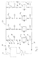
- FIG. 2 shows schematically one of several synchronous motors 11a, 11b, 11c and 11d according to the invention, in particular a plurality of permanent magnet synchronous motors or torque motors 11a, 11b, 11c and 11d, associated, closed cooling water circuit 50.
- the circuit has a plurality of cooling water branches 52a, 52b, 52c and 52d, which are supplied to each other in parallel via a common inlet 54 from a cooling water sucking from a reservoir 56 pump 58 with cooling water and open into a common outlet 60 which leads via a heat exchanger assembly 62 into the reservoir 56.
- the cooling water branches are each designed with shut-off valves, which are designated 64, 66 and 68 in the case of the cooling water branch 52a.
- the cooling water branches are each provided with a dirt filter (dirt filter 70 in the case of the cooling water branch 52a) and a flow monitor (flow switch 72 in the case of the cooling water branch 52a) and with a manually or preferably by means of a remotely controllable actuator adjustable aperture (aperture 74 in the case of the cooling water branch 52a ) and an input side temperature sensor (temperature sensor 76 in the case of the cooling water branch 52a) and an output side temperature sensor (temperature sensor 78 in the case of the cooling water branch 52a) with respect to the respective engine.
- a dirt filter dirty filter 70 in the case of the cooling water branch 52a
- flow monitor flow switch 72 in the case of the cooling water branch 52a
- a dirt filter arrangement can also be arranged in the common inlet 54, preferably on the input side in the pump 58.
- the cooling water circuit 50 is preferably made of corrosion-free components, in particular stainless steel components (in particular Stainless steel piping), manufactured so that it can be dispensed with corrosion inhibitors in the coolant.
- a condensate discharge from the engine or from the region of the engine into the cooling water flowing out from the engine and thus into the reservoir 56 preferably a condensate discharge from the engine or from the region of the engine into the cooling water flowing out from the engine and thus into the reservoir 56.
- a corresponding condensate discharge line is designated 80 and can be provided with suitable valves and the like.
- the cooling water circuit may also have a bypass branch 82 parallel to the cooling water branches, which is designed with a pressure relief valve 84 symbolized by a check valve. This valve opens only when a preset maximum pressure is exceeded to avoid damage due to overpressure.
- FIG. 3 shows an example of a winding machine 100 designed according to the invention with synchronous motors, namely permanent magnet synchronous motors or torque motors, for direct drive of the drums, which has a primary winder 102 and a secondary winder 104.
- the two winders each have one, the synchronous motor according to the invention having drive unit 10a and 10b, for example, according to the drive unit 10 of FIG. 1, in Fig. 3, not all details of this drive unit can be seen.
- the cuboid motor lanterns 12a and 12b can be seen. According to FIG.
- the motor lantern 12b is arranged on a carriage 105b which, after transfer of the winding roller 106 from the primary winder 102 to the secondary winder 104, is displaceable along a linear guide path arranged on a chair 14b in accordance with a linear displacement of the winding roller 106 rotationally driven by the secondary winder 104.
- the motor lantern 12a of the primary winder is held on a pivotally mounted on a chair 14a pivot lever 1 14 and can be pivoted along an arcuate guideway, according to a pivoting of the primary winder associated winding roller 106.
- Their drum 108 is held for this purpose in a pivot lever assembly 116.
- a "Tambourein Wegvorraum” may be provided, comprising a motor output hub corresponding to the motor output hub 16, a sliding or Koppelnabe corresponding to the sliding hub 18 (with an outer toothing 20 corresponding outer teeth) and an engaging lever corresponding to the engagement lever 28.
- the beschiegbarte also as a sliding sleeve sliding hub 18 thus engages radially inside in a sleeve-like coupling end 24 of the respective spool, technically in the "Tambourglocke” a.
- the winding machine according to FIG. 3 has, as is known, a pressure drum or pressure roller 110, also referred to as a supporting drum, which forms a winding gap with the winding roller 106.
- This Anpresstrommel (carrier drum) or pressure roller is also rotatably driven according to the invention proposals by means of a preferably designed as a permanent magnet torque motor synchronous motor, the part of the drive unit 10 of FIG. 1 substantially corresponding Drive unit 10c is.
- a permanent coupling with a rotating shaft 112 of the Anpresstrommel (carrier drum) or pressure roller for example by means of a permanent Drehverkopplung producing coupling sleeve 18c, or a coupling and disengageable coupling, such as by means of a sliding sleeve similar to the embodiment of FIG.
- the drive unit 10c has, as in the embodiment of Fig. 1, a cuboid motor lantern 1 2c, which is arranged on a carriage 105c, which is arranged along a arranged on a chair 15c, comparatively short linear guide track is displaced to a desired contact pressure to keep in the winding nip.
- FIG. 4 shows a schematic side view of the winder 100.
- FIG. 4 is from the published patent application DE 198 22 261 A1 taken there and corresponds to FIG. 1. There were the reference numerals of DE 198 22 261 A1 maintained.
- the element 32 is the drive unit 10a, the element 50 the drive unit 10b, the drum or roller 18 the tapping drum (carrier drum) or pressure roller 110, the element 14 As the primary winder associated drum 108 and the element 14 as already passed to the secondary winder drum (not shown in Fig. 3) to identify.
- 30 denotes the primary winder associated, arcuate guideway along which the drive unit 10a is pivoted.
- the drive units are designed with direct center drives on the basis of synchronous motors without the interposition of bevel gearboxes, gear shafts and the like, as with reference to FIGS. 1 and 3 explained. This represents the most important improvement according to the invention according to the solution DE 198 22 261 A1 represents.
- the features listed above may be provided individually or in combination in connection with winding machines according to the invention and can also be used in other fields of application of the invention proposals, such as in a drying cylinder direct drive in a dryer section.
- the high-temperature grease lubrication is of particular importance, since a flow of fat can be avoided.
- the dropping point is above 230 ° C or even above 250 ° C.
- a cooling water flow of 5 to 50 liters / minute, preferably 5 to 30 liters / minute is considered, for example, at a feed temperature of 5 to 50 ° C, optionally 5 to 35 ° C.
- a lower inlet temperature is usually hardly expedient to avoid condensation.
- the feed temperature should preferably be greater than 50 ° C, preferably 60 to 70 ° C.
- the return temperature should preferably be greater by 2 ° Kelvin than the inlet temperature.
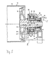
- Fig. 5 shows an example of an application of a motor according to the invention for the direct drive of a drying cylinder 10.
- the plugged onto a shaft journal 13 drive motor 17 is designed as a permanent magnet synchronous motor or torque motor with integrated liquid cooling.
- a feed line Z and a return line R are guided through openings 35, 36, which are connected to terminals of the running with cooling channels, windings 29 having stator 27.
- the rotatably mounted on the shaft journal 13 mounted rotor 24 is designed with permanent magnets 23, which are preferably made on a rare earth basis in order to produce high torques can.
- a heat-insulating layer 26 between the rotor 24 and the shaft journal 13 prevents excessive heating of the electric motor with the aforementioned liquid cooling.
- a corresponding, direct drive according to the invention by means of a slip-on motor is also suitable for other rotary components of a papermaking machine or coater, for example in guide rollers, stabilizer rollers, etc.
- Fig. 6a the dryer section 200 of a paper machine is schematically shown, which has a plurality of drying cylinders.
- Fig. 6a is represented as a representative of all drying cylinders only one drying cylinder 202.
- the drying cylinder 202 is driven by means of an electric motor 204 which is in rotary drive connection via a gear connection 206 to the drying cylinder 202.
- the electric motor 204 is arranged on the drive side TS of the machine.
- the machine points on the drive side a small distance to a wall W on. Worn rotary components, for example drying cylinders or guide rollers of the paper machine, can be exchanged for the guide side FS. On this side, the machine is at a sufficient distance from the next machine or wall.
- the drying cylinder is supplied with working steam via a steam supply line 208 and a steam head 210.
- the steam line 208 and the steam head 210 are arranged on the drive side.
- the removal of condensate also takes place towards the drive side.
- a stiffening of the machine is symbolized by longitudinal members 212 and 214.
- the electric motor 204 and the transmission link 206 are removed. Instead, on the guide side FS a preferably as a synchronous motor, in particular torque motor, executed plug-on motor 220 is installed, which acts directly on a shaft journal 203 of the drying cylinder 202 in the sense of a direct drive.
- the steam continues to be supplied via the steam line 208 and the steam head 210.
- Fig. 7 shows a dryer section of a dryer section having a plurality of dryer cylinders 202a driven and a plurality of non-driven dryer cylinders 202b and associated guide or guide rollers 216a which are driven and guide rollers 216b which are not driven.
- the drive motors 220 of the driven drying cylinders 202a are located on the driver's side, whereas the drive motors 222 driving the guide rollers 216a are on the drive side.
- the drive motors 220 as well as the drive motors 222 are designed as direct drive plug-on motors and on a respective shaft of the respective drying cylinder or the relevant guide or guide roller attached.
- the drive motors 220 and 222 are preferably designed as synchronous motors, in particular torque motors.
- Advantages of the machine according to the invention or of the machine section according to the invention, in the example of the dryer section according to the invention, include the following:
- the use of a plug-on direct drive motor allows the elimination of mechanical drive elements such as gears, clutches and drive shafts.
- several slip motors per dryer group can be used, which can advantageously be arranged on the guide side.
- synchronous motors in particular torque motors, or asynchronous motors can be used as needed.
- Synchronous motors in particular torque motors
- Permanent magnets in particular rare-earth magnets
- the motors usually have a compact, robust design, are largely maintenance-free and wear-free and relatively quiet. It is a backlash-free drive possible.
- a heat dissipation can be done advantageously by a water cooling, so that the motors are also suitable for high ambient temperatures.
- the motors themselves can have a low moment of inertia and provide a nearly constant torque over a wide speed range. Due to its high dynamics, such an engine can react quickly to control processes.
- a high repeat accuracy is possible in principle.
- a noise encapsulation can be provided, in particular by means of water cooling on a fan unit can be dispensed with, so that in this respect a reduced noise emission can be achieved.
- Such motors generally have high availability and, moreover, are highly overloadable. It is possible to approach nominal turning positions with the highest accuracy.
- Asynchronous motors also have advantageous features.
- asynchronous motors are available, which are also designed as Aufsteck- or hollow shaft motor.
- Asynchronous motors may have a compact design and be designed with an integrated water cooling.
- the invention provides a machine or a machine section in which there is at least one drive for at least one roller or at least one other rotary component on the driver's side. It is thought, for example, to a former or headbox, a press and a dryer section. Particularly useful in this context is the execution of the relevant drive as plug-on electric motor, which acts as a direct drive motor, ie without PTO shaft or gear and the like, directly to the relevant roller or rotary component. Specifically, the design of the respective drive motor as Aufsteckmotor allows particularly favorable arrangement of the motor on the driver's side, without the accessibility of the operating side (guide page) of the machine or the machine section is disruptively limited. This is especially important in connection with a dryer section.
- the solution according to the invention is expedient in particular in connection with the conversion of an existing machine or an existing machine section.
- the steam heads for the steam supply to the drying cylinders are often on the drive side.
- the proposed drive the drying cylinder or other associated rotary components on the driver's side allows in particular in the case of using a respective Aufsteckmotors that a costly conversion of the steam supply can be omitted from the drive side to the driver's side.
- the existing steam heads and existing steam supply infrastructure can continue to be used.
- the arrangement of at least one electric motor on the driver's side is not only in connection with the conversion of an existing machine or an existing machine section of interest, but that it also comes into consideration, newly installed machines from the outset with at least one on the driver's side arranged electric motor, possibly synchronous motor and / or Aufsteckmotor execute. This results in additional degrees of freedom for the designer, which can be suitably taken into account, for example, special space requirements.
- a machine or a machine section for the production and / or finishing and / or other treatment or / and handling of a moving material web, in particular of paper or cardboard comprising at least one rotary component, which is drivable by at least one electric motor, one with the rotary component in the Sense of a rotary drive coupled or coupled rotor and a directly or indirectly to a stiffening of the machine or the
- the electric motor is designed or operated as a synchronous motor and that the electric motor is arranged coaxially with the rotary component in association with an axial end region thereof or can be arranged, wherein the rotor or a rotary drive terminal of the same for non-play common rotation rotatably coupled directly to the rotary component or a rotary drive terminal thereof or can be coupled.
- the rotary component can be, for example, a drying cylinder in a drying section or around the winding core of a winding roll in a machine or a machine section for winding the material web onto the winding core to the winding roll and / or for unwinding the material web from the winding roll.
Landscapes
- Connection Of Motors, Electrical Generators, Mechanical Devices, And The Like (AREA)
- Paper (AREA)
- Replacement Of Web Rolls (AREA)
Applications Claiming Priority (3)
| Application Number | Priority Date | Filing Date | Title |
|---|---|---|---|
| DE10312198 | 2003-03-19 | ||
| DE102004001467A DE102004001467A1 (de) | 2003-03-19 | 2004-01-09 | Maschine oder Maschinenabschnitt mit wenigstens einem vorzugsweise als Synchronmotor oder/und Aufsteckmotor ausgeführten und zum Direktantrieb eines Wickelkerns einer Wickelrolle oder zum Direktantrieb einer sonstigen Drehkomponente dienenden Elektromotor, insbesondere zur Verwendung in der Papierindustrie, und sich hierauf beziehendes Umbauverfahren |
| EP20040006599 EP1460010B1 (fr) | 2003-03-19 | 2004-03-18 | Machine avec moteur électrique, de préférence moteur synchrone, pour entraîner directement le noyau d' une bobine, spécialement pour l'usage dans l'industrie de papier, et méthode de transformation en rapport avec cette machine |
Related Parent Applications (1)
| Application Number | Title | Priority Date | Filing Date |
|---|---|---|---|
| EP20040006599 Division EP1460010B1 (fr) | 2003-03-19 | 2004-03-18 | Machine avec moteur électrique, de préférence moteur synchrone, pour entraîner directement le noyau d' une bobine, spécialement pour l'usage dans l'industrie de papier, et méthode de transformation en rapport avec cette machine |
Publications (1)
| Publication Number | Publication Date |
|---|---|
| EP1787929A1 true EP1787929A1 (fr) | 2007-05-23 |
Family
ID=32826218
Family Applications (3)
| Application Number | Title | Priority Date | Filing Date |
|---|---|---|---|
| EP07004788A Expired - Lifetime EP1790599B1 (fr) | 2003-03-19 | 2004-03-18 | Machine ou section de machine dotée d'au moins un électromoteur destiné à l'engrenage direct d'un axe d'enroulement d'une bobine d'enroulement, en particulier destiné à l'utilisation dans l'industrie du papier |
| EP07004789A Ceased EP1787929A1 (fr) | 2003-03-19 | 2004-03-18 | Machine ou section de machine dotée d'au moins un électromoteur développé de préférence en tant que moteur synchrone et/ou à emboîtement et destiné à l'engrenage direct d'un axe d'enroulement d'une bobine d'enroulement ou à l'engrenage direct d'un autre composant de rotation, en particulier destiné à l'utilisation dans l'industrie du papier, et son procédé de transformation |
| EP20040006599 Expired - Lifetime EP1460010B1 (fr) | 2003-03-19 | 2004-03-18 | Machine avec moteur électrique, de préférence moteur synchrone, pour entraîner directement le noyau d' une bobine, spécialement pour l'usage dans l'industrie de papier, et méthode de transformation en rapport avec cette machine |
Family Applications Before (1)
| Application Number | Title | Priority Date | Filing Date |
|---|---|---|---|
| EP07004788A Expired - Lifetime EP1790599B1 (fr) | 2003-03-19 | 2004-03-18 | Machine ou section de machine dotée d'au moins un électromoteur destiné à l'engrenage direct d'un axe d'enroulement d'une bobine d'enroulement, en particulier destiné à l'utilisation dans l'industrie du papier |
Family Applications After (1)
| Application Number | Title | Priority Date | Filing Date |
|---|---|---|---|
| EP20040006599 Expired - Lifetime EP1460010B1 (fr) | 2003-03-19 | 2004-03-18 | Machine avec moteur électrique, de préférence moteur synchrone, pour entraîner directement le noyau d' une bobine, spécialement pour l'usage dans l'industrie de papier, et méthode de transformation en rapport avec cette machine |
Country Status (1)
| Country | Link |
|---|---|
| EP (3) | EP1790599B1 (fr) |
Cited By (1)
| Publication number | Priority date | Publication date | Assignee | Title |
|---|---|---|---|---|
| EP2003060A1 (fr) * | 2007-06-15 | 2008-12-17 | CFS Weert B.V. | Machine d'emballage avec un moteur contrôlé par couplage |
Families Citing this family (15)
| Publication number | Priority date | Publication date | Assignee | Title |
|---|---|---|---|---|
| WO2005073114A2 (fr) * | 2004-01-30 | 2005-08-11 | Koenig & Bauer Aktiengesellschaft | Entrainements d'un changeur de bobines |
| DE102005000037A1 (de) | 2005-04-19 | 2006-10-26 | Voith Patent Gmbh | Walzenantrieb |
| DE102005000116A1 (de) * | 2005-09-14 | 2007-03-15 | Voith Patent Gmbh | Wickelmaschine zum Aufwickeln einer Materialbahn |
| DE102005000118A1 (de) | 2005-09-15 | 2007-03-22 | Voith Patent Gmbh | Antriebseinheit für eine Wickelmaschine zum Wickeln einer Materialbahn |
| DE102005000171A1 (de) | 2005-11-28 | 2007-05-31 | Voith Patent Gmbh | Wickelmaschine zum Aufwickeln einer Materialbahn |
| DE102008000042A1 (de) * | 2007-09-24 | 2009-04-02 | Voith Patent Gmbh | Verfahren und Vorrichtung zum Aufwickeln einer Materialbahn |
| CN101607643B (zh) * | 2008-06-18 | 2011-05-04 | 上海格林赛高新材料有限公司 | 带材连续卷取装置 |
| ES2482390B1 (es) * | 2012-10-08 | 2015-05-12 | Comexi Group Industries S.A.U. | Método y sistema de ajuste de tensión en rebobinado para una máquina con una estación de rebobinado, programa de ordenador que implementa el método y máquina con estación de rebobinado |
| CN103466365B (zh) * | 2013-09-07 | 2016-10-26 | 沧州华海风电设备科技技术开发有限公司 | 胶带集带机 |
| CN105619890A (zh) * | 2016-03-02 | 2016-06-01 | 湖州上银机械科技有限公司 | 瓦楞机双摇臂预热范围可调结构 |
| CH713894A1 (de) * | 2017-06-15 | 2018-12-28 | Rieter Ag Maschf | Vorrichtung an einer Spinnereivorbereitungsmaschine. |
| DE102017214414A1 (de) * | 2017-08-18 | 2019-02-21 | Sms Group Gmbh | Direktantrieb für Saumwickler in der Metallbearbeitung |
| AT523514B1 (de) * | 2020-02-13 | 2021-11-15 | Friedrich Haeupl Ing | Vorrichtung zum Sortieren von Stämmen |
| CN113135321B (zh) * | 2021-04-23 | 2023-03-17 | 上海乐纯生物技术有限公司 | 一种封管机 |
| DE102022120317A1 (de) | 2022-08-11 | 2024-02-22 | Voith Patent Gmbh | Walzenantriebsvorrichtung für eine Walze einer Maschine zur Herstellung oder Behandlung einer Faserstoffbahn |
Citations (6)
| Publication number | Priority date | Publication date | Assignee | Title |
|---|---|---|---|---|
| DE8703410U1 (de) * | 1987-03-06 | 1987-05-21 | J.M. Voith Gmbh, 7920 Heidenheim | Trockenzylinder od.dgl. einer Papier-, Karton- oder Streichmaschine |
| WO2001086781A1 (fr) * | 2000-05-05 | 2001-11-15 | Abb Research Ltd | Entrainement pour rouleaux mobiles |
| DE10025316A1 (de) * | 2000-05-22 | 2001-11-29 | Voith Paper Patent Gmbh | Antriebseinheit |
| AT409853B (de) * | 2001-01-22 | 2002-12-27 | Andritz Ag Maschf | Vorrichtung zum kontinuierlichen aufwickeln einer faserstoffbahn |
| EP1841046A1 (fr) * | 2005-01-17 | 2007-10-03 | Toyota Jidosha Kabushiki Kaisha | Machine electrique rotative |
| US20100264760A1 (en) * | 2009-04-21 | 2010-10-21 | Nippon Soken, Inc. | Electric rotating machine |
Family Cites Families (18)
| Publication number | Priority date | Publication date | Assignee | Title |
|---|---|---|---|---|
| FI76766C (fi) * | 1986-02-27 | 1990-04-24 | Ahlstroem Valmet | Anordning foer uppbromsning av en pappers- eller kartongmaskins maskinrulle. |
| US4804898A (en) * | 1988-02-22 | 1989-02-14 | Rapid-Air Corporation | Stock feed apparatus |
| SE469071B (sv) * | 1991-09-18 | 1993-05-10 | Valmet Karlstad Ab | Rullstol med centrumdriven upprullningsvals |
| DE59309453D1 (de) * | 1992-10-28 | 1999-04-22 | Anton Rueegg | Vorrichtung zum Aufwickeln einer kontinuierlich zugeführten Materialbahn auf eine Anzahl von Wickelkernen |
| US5622328A (en) * | 1993-09-16 | 1997-04-22 | Norley; Michael | Paper winder for winding a length of waste paper from a paper cup making machine |
| DE4401959C2 (de) * | 1994-01-24 | 1996-07-25 | Voith Gmbh J M | Tragtrommelroller für eine Papiermaschine |
| DE19735590A1 (de) * | 1997-05-16 | 1998-11-19 | Voith Sulzer Papiermasch Gmbh | Wickelmaschine zum Aufwickeln einer Materialbahn |
| DE19722209A1 (de) | 1997-05-27 | 1998-12-03 | Voith Sulzer Papiermasch Gmbh | Abrollstation zum kontinuierlichen Abwickeln einer Materialbahn |
| DE19742787A1 (de) * | 1997-09-27 | 1999-04-01 | Voith Sulzer Papiertech Patent | Haube |
| DE19822261A1 (de) | 1998-05-18 | 1999-11-25 | Voith Sulzer Papiertech Patent | Verfahren und Wickelmaschine zum Aufwickeln einer Materialbahn |
| FI120104B (fi) * | 2000-05-05 | 2009-06-30 | Abb Research Ltd | Telakäyttö |
| ATE338893T1 (de) * | 2000-05-22 | 2006-09-15 | Voith Paper Patent Gmbh | Antriebseinheit |
| DE10035578B4 (de) * | 2000-07-21 | 2010-02-18 | Voith Patent Gmbh | Antriebseinheit |
| AT409852B (de) * | 2001-01-22 | 2002-12-27 | Andritz Ag Maschf | Vorrichtung zum kontinuierlichen aufwickeln einer faserstoffbahn |
| DE10117398A1 (de) * | 2001-04-06 | 2002-10-10 | Miscel Oy Ltd | Elektrischer Asynchronmotor |
| DE10137063A1 (de) * | 2001-07-28 | 2003-02-13 | Voith Paper Patent Gmbh | Verfahren und Wickelmaschine zum kontinuierlichen Aufwickeln einer Materialbahn |
| FI116217B (fi) * | 2001-08-27 | 2005-10-14 | Metso Paper Inc | Menetelmä rullan siirtämiseksi ja rullain |
| DE10203089A1 (de) * | 2002-01-28 | 2003-07-31 | Voith Paper Patent Gmbh | Antriebseinheit |
-
2004
- 2004-03-18 EP EP07004788A patent/EP1790599B1/fr not_active Expired - Lifetime
- 2004-03-18 EP EP07004789A patent/EP1787929A1/fr not_active Ceased
- 2004-03-18 EP EP20040006599 patent/EP1460010B1/fr not_active Expired - Lifetime
Patent Citations (6)
| Publication number | Priority date | Publication date | Assignee | Title |
|---|---|---|---|---|
| DE8703410U1 (de) * | 1987-03-06 | 1987-05-21 | J.M. Voith Gmbh, 7920 Heidenheim | Trockenzylinder od.dgl. einer Papier-, Karton- oder Streichmaschine |
| WO2001086781A1 (fr) * | 2000-05-05 | 2001-11-15 | Abb Research Ltd | Entrainement pour rouleaux mobiles |
| DE10025316A1 (de) * | 2000-05-22 | 2001-11-29 | Voith Paper Patent Gmbh | Antriebseinheit |
| AT409853B (de) * | 2001-01-22 | 2002-12-27 | Andritz Ag Maschf | Vorrichtung zum kontinuierlichen aufwickeln einer faserstoffbahn |
| EP1841046A1 (fr) * | 2005-01-17 | 2007-10-03 | Toyota Jidosha Kabushiki Kaisha | Machine electrique rotative |
| US20100264760A1 (en) * | 2009-04-21 | 2010-10-21 | Nippon Soken, Inc. | Electric rotating machine |
Cited By (2)
| Publication number | Priority date | Publication date | Assignee | Title |
|---|---|---|---|---|
| EP2003060A1 (fr) * | 2007-06-15 | 2008-12-17 | CFS Weert B.V. | Machine d'emballage avec un moteur contrôlé par couplage |
| WO2008151816A1 (fr) * | 2007-06-15 | 2008-12-18 | Cfs Weert B.V. | Machine d'emballage à moteur contrôlé par couple |
Also Published As
| Publication number | Publication date |
|---|---|
| EP1460010A2 (fr) | 2004-09-22 |
| EP1460010A3 (fr) | 2005-11-16 |
| EP1790599A1 (fr) | 2007-05-30 |
| EP1460010B1 (fr) | 2010-08-04 |
| EP1790599B1 (fr) | 2010-08-25 |
Similar Documents
| Publication | Publication Date | Title |
|---|---|---|
| EP1460010B1 (fr) | Machine avec moteur électrique, de préférence moteur synchrone, pour entraîner directement le noyau d' une bobine, spécialement pour l'usage dans l'industrie de papier, et méthode de transformation en rapport avec cette machine | |
| DE10024327C2 (de) | Antrieb eines rotierenden Bauteils einer Druckmaschine und Verfahren zum Trennen eines Antriebes | |
| WO2008046737A1 (fr) | Dispositif de transmission comprenant au moins un élément de commutation pouvant être actionné par le biais d'un dispositif d'actionnement présentant au moins un composant électrique | |
| DE19509417A1 (de) | Antriebseinheit | |
| DE102017214412A1 (de) | Direktantrieb bei Rollen, Walzen und Winden in der Stahl/NE-Industrie | |
| EP1262278B1 (fr) | Révolver porte-outil | |
| EP1158188B1 (fr) | Dispositif d'entraînement | |
| EP2593685A2 (fr) | Dispositif pour façonner une matière en forme de bande ou de feuille | |
| DE102008009351A1 (de) | Vorrichtung zur Drehmomentbegrenzung in einem Triebstrang | |
| DE102004001467A1 (de) | Maschine oder Maschinenabschnitt mit wenigstens einem vorzugsweise als Synchronmotor oder/und Aufsteckmotor ausgeführten und zum Direktantrieb eines Wickelkerns einer Wickelrolle oder zum Direktantrieb einer sonstigen Drehkomponente dienenden Elektromotor, insbesondere zur Verwendung in der Papierindustrie, und sich hierauf beziehendes Umbauverfahren | |
| EP3668808B1 (fr) | Entraînement direct d'un enrouleur de filet dans le domaine du travail des métaux | |
| WO2005073114A2 (fr) | Entrainements d'un changeur de bobines | |
| DE29908433U1 (de) | Walze | |
| WO2004042897A1 (fr) | Entrainement direct destine a un cylindre | |
| DE10035578B4 (de) | Antriebseinheit | |
| DE102005045406B4 (de) | Verwendung eines elektromotorischen Direktantriebes als Antrieb einer kontinuierlichen Presse | |
| EP2801660B1 (fr) | Entraînement et système comprenant au moins un cylindre entraîné ou une vis sans fin d'extrusion | |
| DE10324314B4 (de) | Lüfterantrieb für Kraftfahrzeuge | |
| DE69814908T2 (de) | Karussellwickelrolle | |
| DE102011002516B4 (de) | Antriebsvorrichtung einer Druckmaschine | |
| DE102006060853A1 (de) | Walzenantriebseinheit | |
| EP1580317B1 (fr) | Entraînement à câble avec moteur à arbre creux | |
| EP3668661B1 (fr) | Procédé et dispositif pour le freinage électrique pourvus d'un dispositif de retenue mécanique pour un entraînement direct lors du travail des métaux | |
| EP1835073A1 (fr) | Cylindre monté rotatif | |
| EP1749928A1 (fr) | Dispositif pour la fabrication et/ou le traitement d'une bande |
Legal Events
| Date | Code | Title | Description |
|---|---|---|---|
| PUAI | Public reference made under article 153(3) epc to a published international application that has entered the european phase |
Free format text: ORIGINAL CODE: 0009012 |
|
| 17P | Request for examination filed |
Effective date: 20070308 |
|
| AC | Divisional application: reference to earlier application |
Ref document number: 1460010 Country of ref document: EP Kind code of ref document: P |
|
| AK | Designated contracting states |
Kind code of ref document: A1 Designated state(s): AT BE BG CH CY CZ DE DK EE ES FI FR GB GR HU IE IT LI LU MC NL PL PT RO SE SI SK TR |
|
| AKX | Designation fees paid |
Designated state(s): AT BE BG CH CY CZ DE DK EE ES FI FR GB GR HU IE IT LI LU MC NL PL PT RO SE SI SK TR |
|
| 17Q | First examination report despatched |
Effective date: 20080114 |
|
| STAA | Information on the status of an ep patent application or granted ep patent |
Free format text: STATUS: THE APPLICATION HAS BEEN REFUSED |
|
| 18R | Application refused |
Effective date: 20130205 |