EP1787932A2 - Méthode et enrouleuse pour enrouler une bande de materiau - Google Patents
Méthode et enrouleuse pour enrouler une bande de materiau Download PDFInfo
- Publication number
- EP1787932A2 EP1787932A2 EP06123085A EP06123085A EP1787932A2 EP 1787932 A2 EP1787932 A2 EP 1787932A2 EP 06123085 A EP06123085 A EP 06123085A EP 06123085 A EP06123085 A EP 06123085A EP 1787932 A2 EP1787932 A2 EP 1787932A2
- Authority
- EP
- European Patent Office
- Prior art keywords
- winding
- material web
- glue
- web
- roll
- Prior art date
- Legal status (The legal status is an assumption and is not a legal conclusion. Google has not performed a legal analysis and makes no representation as to the accuracy of the status listed.)
- Withdrawn
Links
- 238000004804 winding Methods 0.000 title claims abstract description 97
- 239000000463 material Substances 0.000 title claims abstract description 50
- 238000000034 method Methods 0.000 title claims abstract description 10
- 239000003292 glue Substances 0.000 claims abstract description 44
- XLYOFNOQVPJJNP-UHFFFAOYSA-N water Substances O XLYOFNOQVPJJNP-UHFFFAOYSA-N 0.000 claims description 3
- 230000000977 initiatory effect Effects 0.000 claims 1
- 238000011161 development Methods 0.000 description 2
- 230000018109 developmental process Effects 0.000 description 2
- 230000001154 acute effect Effects 0.000 description 1
- 239000000853 adhesive Substances 0.000 description 1
- 238000004026 adhesive bonding Methods 0.000 description 1
- 230000001070 adhesive effect Effects 0.000 description 1
- 238000003490 calendering Methods 0.000 description 1
- 238000000926 separation method Methods 0.000 description 1
Images
Classifications
-
- B—PERFORMING OPERATIONS; TRANSPORTING
- B65—CONVEYING; PACKING; STORING; HANDLING THIN OR FILAMENTARY MATERIAL
- B65H—HANDLING THIN OR FILAMENTARY MATERIAL, e.g. SHEETS, WEBS, CABLES
- B65H19/00—Changing the web roll
- B65H19/22—Changing the web roll in winding mechanisms or in connection with winding operations
- B65H19/28—Attaching the leading end of the web to the replacement web-roll core or spindle
- B65H19/286—Attaching the leading end of the web to the replacement web-roll core or spindle by applying adhesive to the web
-
- B—PERFORMING OPERATIONS; TRANSPORTING
- B65—CONVEYING; PACKING; STORING; HANDLING THIN OR FILAMENTARY MATERIAL
- B65H—HANDLING THIN OR FILAMENTARY MATERIAL, e.g. SHEETS, WEBS, CABLES
- B65H19/00—Changing the web roll
- B65H19/22—Changing the web roll in winding mechanisms or in connection with winding operations
- B65H19/26—Cutting-off the web running to the wound web roll
- B65H19/267—Cutting-off the web running to the wound web roll by tearing or bursting
-
- B—PERFORMING OPERATIONS; TRANSPORTING
- B65—CONVEYING; PACKING; STORING; HANDLING THIN OR FILAMENTARY MATERIAL
- B65H—HANDLING THIN OR FILAMENTARY MATERIAL, e.g. SHEETS, WEBS, CABLES
- B65H2301/00—Handling processes for sheets or webs
- B65H2301/40—Type of handling process
- B65H2301/41—Winding, unwinding
- B65H2301/414—Winding
- B65H2301/4148—Winding slitting
Definitions
- the invention relates to a method for winding a material web, in particular a paper or board web, on at least one winding tube to at least one winding roll by means of at least one roller on which the winding roll on winding up or rests.
- Material webs must be wound up on shipping or finishing rolls before they can be shipped.
- reel cores usually winding cores are used, which are preferably made of cardboard.
- the finished rolls are produced in that so-called mother or spool rolls, which are produced at the exit of a paper machine or after the calendering, unwound, cut in the longitudinal direction and then wound on each winding cores.
- mother or spool rolls which are produced at the exit of a paper machine or after the calendering, unwound, cut in the longitudinal direction and then wound on each winding cores.
- These cores are either on a support roller of a back-up roll winding machine or laterally on this, or the cores are in one of two support rollers of a double carrier roll winding machine formed winding bed.
- a backup roll winding machine In the EP 0 829 438 B1 a backup roll winding machine will be described.
- a material web supported on a support roller, wound on a winding tube, while passing through a gap formed between the support roller and the wound roll to be produced, wherein the winding roll is additionally supported by a further, two small rollers device .
- a back-up roll winding machine either only a single winding roll may be wound or a plurality of winding rolls each held in winding stations by individual jigs, the jigs alternating the winding rolls alternately on both sides from a vertical through the center of the support roll Keep axis, wherein the connecting lines between the centers of the bobbins and the support roller are inclined in each case to both sides of the vertical at an acute angle or form a right angle with the vertical.
- the clamping heads and the winding tubes in the winding stations can also have different diameters.
- this object is achieved in a method of the type mentioned above in that the material web when changing from a full, wound on the at least one winding core winding roll to at least one empty winding tube with a, based on the web running direction, is provided diagonally extending glue track, that the material web is wound through the glue track to the at least one empty winding tube and at the same time tears off in the web running direction in front of the glue lane.
- the material web breaks off automatically in the web running direction in front of the bond in the (at least substantially) diagonal glue connection between the web and the empty winding tube, ensures that the web always breaks without a separate separating or cutting device, as in the state the technique required, must be used.
- the initial gluing can be realized with only a single glue nozzle, which is moved across a traverse transverse to the web running direction while the web is running, so that a diagonal glue application results.
- the material web is perforated in the web running direction before the glue track. This assists in precisely tearing or tearing the web immediately before the diagonal glue strip when the web is joined by the glue strip to the empty winding tube.
- the invention also relates to a winding machine for winding a material web, in particular a paper or board web, on at least one winding tube to at least one winding roll by means of at least one roller on which the winding roll when winding up or rests.
- the Winding machine at least a single glue nozzle for applying glue on the moving material web, wherein by the glue nozzle to initiate the change from a full winding roll on at least one empty winding tube glue on the material web transverse to its direction can be applied.
- the glue nozzle is arranged pivotably over substantially the entire width of the material web and that during the pivoting movement of the glue nozzle glue transverse to the running direction of the web to which this can be applied.
- a perforating different devices can provide, for example, a laser, a water jet or a perforating roller.
- a perforation roller is in principle of the principle of the DE 36 11 895 C2 known.
- this web-width perforating roller is adapted such that it has a comb applied diagonally on its lateral surface, which, when pressed against the material web, introduces a perforation into it. Therefore, the perforating roller, while rotating at the same time, is pressed against the web of material immediately before the glue line is applied, thereby creating a diagonal perforation in the web.
- the winding machine has at least one Glue nozzle comprises, which is mounted on a crossmember and on this substantially over the entire width of the material web is movable, so that, as the web moves in the longitudinal direction, a diagonal glue line is applied to this. Even with a single glue nozzle, the invention can be carried out.
- a glue nozzle attached in the vicinity of the material web can be pivoted essentially over the entire width of the material web, so that a diagonal application of the glue to it is produced during the course of the material web.
- the winding machine can be provided with a perforating means, through which the material web can be perforated substantially over its entire width.
- the perforating means can advantageously be designed alternatively as a laser, as a water jet or as a perforating roller.
- the invention is used, for example, in a winding device formed by a double-carrier roller winding machine, which has two carrier rollers, of which at least one is driven.
- the support rollers form a roller bed, in which several adjacent winding rollers rest during winding on the support rollers.
- a material web in particular a paper or board web, cut before winding into a plurality of individual webs, which are then passed through the gap between the support rollers or laterally around the shell of one of the two support rollers around in the roll bed, where they are aligned lined up winding tubes are wound up.
- the sleeves When the sleeves are fully wound, that is, when they have reached a specific, fixed winding position, for example, by a pivoting device, a corresponding number of new unwound and aligned successively arranged cores placed in the vicinity of the web, ie in one Anwickelposition to connect to the cores, so that the cores can be inserted into the winding bed when the full cores are lifted by the same pivoting device or another pivoting device from its winding bed.
- the cores and the finished bobbins need not necessarily be in a row.
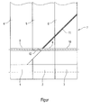
- This shows a plan view of a material web in the region of a winding device with a lying for example in a support bed set of juxtaposed bobbins 1, 2, 3, already (almost) completely with side by side running strips 4, 5, 6 of a web 7 are wound.
- the strips 4, 5, 6 are brought into contact with the winding cores or sleeves 8, 9, 10, so that the strips adhere to the winding tubes 8, 9, 10 and at the same time tear the strips 4, 5, 6 diagonally in front of the glue track 11, so that a new beginning 12 of the material web 7 is formed, which now first spirally on the winding tubes 8, 9th , 10 is wound until all strips 4, 5, 6 are wound over the entire width of the material web 7 on the new cores 8, 9, 10.
- the new hubs are brought by the same or another device in the position in which previously the full bobbins 1, 2, 3 were arranged.
- the tear-off process of the material web 7 can be assisted by providing the material web 7 with a perforation in the web running direction in front of the glue lane 11.
- the invention can also be used in a winding machine which operates on the backup roll principle.
- the winding of a new set of cores can be done according to the invention at full speed. However, it can also be carried out at reduced speed, depending on the type of material web.
Landscapes
- Replacement Of Web Rolls (AREA)
Applications Claiming Priority (1)
| Application Number | Priority Date | Filing Date | Title |
|---|---|---|---|
| DE200510000159 DE102005000159A1 (de) | 2005-11-17 | 2005-11-17 | Verfahren und Wickelmaschine zum Aufwickeln einer Materialbahn |
Publications (2)
| Publication Number | Publication Date |
|---|---|
| EP1787932A2 true EP1787932A2 (fr) | 2007-05-23 |
| EP1787932A3 EP1787932A3 (fr) | 2008-09-17 |
Family
ID=37775195
Family Applications (1)
| Application Number | Title | Priority Date | Filing Date |
|---|---|---|---|
| EP06123085A Withdrawn EP1787932A3 (fr) | 2005-11-17 | 2006-10-27 | Méthode et enrouleuse pour enrouler une bande de materiau |
Country Status (2)
| Country | Link |
|---|---|
| EP (1) | EP1787932A3 (fr) |
| DE (1) | DE102005000159A1 (fr) |
Citations (6)
| Publication number | Priority date | Publication date | Assignee | Title |
|---|---|---|---|---|
| DE3611895C2 (fr) | 1986-04-09 | 1991-08-14 | Jagenberg Ag, 4000 Duesseldorf, De | |
| EP0553232B1 (fr) | 1990-10-15 | 1995-04-19 | Beloit Technologies, Inc. | Procede de modification de reglage dans une enrouleuse |
| EP0792245B1 (fr) | 1995-11-01 | 1999-06-09 | Valmet Corporation | Procede de bobinage |
| DE20013319U1 (de) | 2000-08-02 | 2000-09-28 | Voith Sulzer Papiertechnik Patent GmbH, 89522 Heidenheim | Bahnanfangsbefestigung |
| DE20015034U1 (de) | 2000-08-31 | 2002-01-24 | Schwarzbich, Jörg, 33615 Bielefeld | Freilauf |
| EP0829438B1 (fr) | 1994-05-26 | 2002-04-03 | Metso Paper, Inc. | Méthode pour enrouler une Bande |
Family Cites Families (5)
| Publication number | Priority date | Publication date | Assignee | Title |
|---|---|---|---|---|
| DE1952205C3 (de) * | 1968-10-17 | 1973-10-31 | Inta-Roto, Inc., Richmond, Va. (V.St.A.) | Verfahren zum selbsttätigen konti nuierhchen Aufwickeln endlos anfallen den bahnförmigen Gutes, insbesondere aus mehreren nebeneinanderlaufenden Teil bahnen bestehenden Gutes, und Vorrichtung zur Durchfuhrung desselben |
| US3918654A (en) * | 1973-07-21 | 1975-11-11 | Rca Corp | Automatic winding apparatus for a strip of material |
| DE29504917U1 (de) * | 1995-03-23 | 1995-06-01 | Maschinenfabrik Goebel Gmbh, 64293 Darmstadt | Einrichtung mit Gehäuse |
| US6045085A (en) * | 1997-04-16 | 2000-04-04 | Valmet-Karlstad Ab | Adhesive dispensing device in a reel-up in a paper machine |
| DE20015032U1 (de) * | 2000-08-31 | 2001-02-22 | Voith Paper Patent GmbH, 89522 Heidenheim | Rollenwickeleinrichtung |
-
2005
- 2005-11-17 DE DE200510000159 patent/DE102005000159A1/de not_active Withdrawn
-
2006
- 2006-10-27 EP EP06123085A patent/EP1787932A3/fr not_active Withdrawn
Patent Citations (6)
| Publication number | Priority date | Publication date | Assignee | Title |
|---|---|---|---|---|
| DE3611895C2 (fr) | 1986-04-09 | 1991-08-14 | Jagenberg Ag, 4000 Duesseldorf, De | |
| EP0553232B1 (fr) | 1990-10-15 | 1995-04-19 | Beloit Technologies, Inc. | Procede de modification de reglage dans une enrouleuse |
| EP0829438B1 (fr) | 1994-05-26 | 2002-04-03 | Metso Paper, Inc. | Méthode pour enrouler une Bande |
| EP0792245B1 (fr) | 1995-11-01 | 1999-06-09 | Valmet Corporation | Procede de bobinage |
| DE20013319U1 (de) | 2000-08-02 | 2000-09-28 | Voith Sulzer Papiertechnik Patent GmbH, 89522 Heidenheim | Bahnanfangsbefestigung |
| DE20015034U1 (de) | 2000-08-31 | 2002-01-24 | Schwarzbich, Jörg, 33615 Bielefeld | Freilauf |
Also Published As
| Publication number | Publication date |
|---|---|
| EP1787932A3 (fr) | 2008-09-17 |
| DE102005000159A1 (de) | 2007-05-24 |
Similar Documents
| Publication | Publication Date | Title |
|---|---|---|
| EP0442038B1 (fr) | Méthode et dispositif pour le remplacement automatique d'une bobine pleine par un nouveau noyau d'enroulement | |
| EP0500841B1 (fr) | Procede et dispositif de changement de rouleaux d'enroulement | |
| EP0672015B1 (fr) | Systeme d'enroulage a rouleaux porteurs | |
| DE2948877A1 (de) | Vorrichtung zum lagegenauen einsetzen von wickelhuelsen in wickelmaschinen | |
| EP1319617B1 (fr) | Méthode pour transférer une bande de matériau en mouvement sur un moyeu d'enroulage et enrouleuse | |
| EP0963909B1 (fr) | Procédé et dispositif pour fabriquer un rouleau de matériau en bande emballée circonférenciellement, et un rouleau de matériau en bande | |
| DE10309049A1 (de) | Verfahren und Vorrichtung zum Überführen einer Materialbahn | |
| DE10161073A1 (de) | Verfahren zum Überführen einer laufenden Materialbahn auf einen Wickelkern sowie Vorrichtung zur Durchführung des Verfahrens | |
| EP1140679B1 (fr) | Procede et dispositif pour le raccord de bandes de materiau | |
| EP1127820B1 (fr) | Dispositif pour raccorder des bandes, en particulier des bandes de papier, pour la production de carton ondulé | |
| DE19753870B4 (de) | Verfahren und Vorrichtung zum Verbinden des Endes einer ersten Materialbahn mit dem Anfang einer zweiten Materialbahn | |
| DE19529177C2 (de) | Verfahren zum Herstellen von Selbstklebeetikettenbändern und nach diesem Verfahren hergestelltes Selbstklebeetikettenband | |
| DE4415316A1 (de) | Rollenwickelmaschine | |
| WO2003068646A1 (fr) | Moyen pour transferer une bande de matiere en mouvement sur un mandrin d'enroulement et son procede d'utilisation | |
| EP1818298B1 (fr) | Méthode et dispositif pour enrouler des bandes de parties de matériau sur des noyaux, pour former des rouleaux de partie de matériau | |
| EP1652803B1 (fr) | Procédé d'enroulement | |
| DE10201410A1 (de) | Verfahren zum Überführen einer laufenden Materialbahn auf einen neuen Wickelkern sowie Vorrichtung zur Durchführung des Verfahrens | |
| DE102005000159A1 (de) | Verfahren und Wickelmaschine zum Aufwickeln einer Materialbahn | |
| DE10206575A1 (de) | Verfahren zum Überführen einer laufenden Materialbahn auf einen Wickelkern und Wickelmaschine | |
| WO1997033821A1 (fr) | Dispositif d'enroulement continu de bandes de papier coupees longitudinalement avec changement automatique des rouleaux a vitesse de la machine | |
| DE19843353C1 (de) | Verfahren und Vorrichtung zum Entfernen von Fehlstellen aus einer Bahn | |
| DE19715548A1 (de) | Wechselvorrichtung einer Maschine zur Herstellung einer Materialbahn | |
| EP1818297A1 (fr) | Méthode et dispositif pour enrouler de materiaux en bandes refendues autour de noyaux en rouleax partiles | |
| DE10163554A1 (de) | Verfahren zum Überführen einer laufenden Materialbahn auf einen Wickelkern sowie Vorrichtung zur Durchführung des Verfahrens | |
| EP1847495A1 (fr) | Procédé, mandrin de bobinage et bobineuse destinés à l'embobinage d'au moins deux bandes de matériau passant l'une à côté de l'autre |
Legal Events
| Date | Code | Title | Description |
|---|---|---|---|
| PUAI | Public reference made under article 153(3) epc to a published international application that has entered the european phase |
Free format text: ORIGINAL CODE: 0009012 |
|
| AK | Designated contracting states |
Kind code of ref document: A2 Designated state(s): AT BE BG CH CY CZ DE DK EE ES FI FR GB GR HU IE IS IT LI LT LU LV MC NL PL PT RO SE SI SK TR |
|
| AX | Request for extension of the european patent |
Extension state: AL BA HR MK YU |
|
| RIN1 | Information on inventor provided before grant (corrected) |
Inventor name: WEBERS, UWE Inventor name: SCHORZMANN, FRANK Inventor name: MAURER, JOERG, DR. Inventor name: KORONAI, ANDREAS Inventor name: KLUPP, ALEXANDER Inventor name: HEHNER, REINHARD |
|
| PUAL | Search report despatched |
Free format text: ORIGINAL CODE: 0009013 |
|
| AK | Designated contracting states |
Kind code of ref document: A3 Designated state(s): AT BE BG CH CY CZ DE DK EE ES FI FR GB GR HU IE IS IT LI LT LU LV MC NL PL PT RO SE SI SK TR |
|
| AX | Request for extension of the european patent |
Extension state: AL BA HR MK RS |
|
| RIC1 | Information provided on ipc code assigned before grant |
Ipc: B65H 19/26 20060101ALI20080814BHEP Ipc: B65H 19/22 20060101ALI20080814BHEP Ipc: B65H 19/28 20060101AFI20070312BHEP |
|
| 17P | Request for examination filed |
Effective date: 20090317 |
|
| AKX | Designation fees paid |
Designated state(s): AT DE FI IT |
|
| 17Q | First examination report despatched |
Effective date: 20090422 |
|
| GRAP | Despatch of communication of intention to grant a patent |
Free format text: ORIGINAL CODE: EPIDOSNIGR1 |
|
| STAA | Information on the status of an ep patent application or granted ep patent |
Free format text: STATUS: THE APPLICATION IS DEEMED TO BE WITHDRAWN |
|
| 18D | Application deemed to be withdrawn |
Effective date: 20130213 |