EP1788206A2 - Moteur à combustion interne avec un dispositif pour séparer l'huile du gaz de ventilation - Google Patents
Moteur à combustion interne avec un dispositif pour séparer l'huile du gaz de ventilation Download PDFInfo
- Publication number
- EP1788206A2 EP1788206A2 EP06022363A EP06022363A EP1788206A2 EP 1788206 A2 EP1788206 A2 EP 1788206A2 EP 06022363 A EP06022363 A EP 06022363A EP 06022363 A EP06022363 A EP 06022363A EP 1788206 A2 EP1788206 A2 EP 1788206A2
- Authority
- EP
- European Patent Office
- Prior art keywords
- oil
- internal combustion
- combustion engine
- delivery device
- crankcase
- Prior art date
- Legal status (The legal status is an assumption and is not a legal conclusion. Google has not performed a legal analysis and makes no representation as to the accuracy of the status listed.)
- Granted
Links
Images
Classifications
-
- F—MECHANICAL ENGINEERING; LIGHTING; HEATING; WEAPONS; BLASTING
- F02—COMBUSTION ENGINES; HOT-GAS OR COMBUSTION-PRODUCT ENGINE PLANTS
- F02B—INTERNAL-COMBUSTION PISTON ENGINES; COMBUSTION ENGINES IN GENERAL
- F02B39/00—Component parts, details, or accessories relating to, driven charging or scavenging pumps, not provided for in groups F02B33/00 - F02B37/00
- F02B39/14—Lubrication of pumps; Safety measures therefor
-
- F—MECHANICAL ENGINEERING; LIGHTING; HEATING; WEAPONS; BLASTING
- F01—MACHINES OR ENGINES IN GENERAL; ENGINE PLANTS IN GENERAL; STEAM ENGINES
- F01M—LUBRICATING OF MACHINES OR ENGINES IN GENERAL; LUBRICATING INTERNAL COMBUSTION ENGINES; CRANKCASE VENTILATING
- F01M1/00—Pressure lubrication
- F01M1/12—Closed-circuit lubricating systems not provided for in groups F01M1/02 - F01M1/10
-
- F—MECHANICAL ENGINEERING; LIGHTING; HEATING; WEAPONS; BLASTING
- F01—MACHINES OR ENGINES IN GENERAL; ENGINE PLANTS IN GENERAL; STEAM ENGINES
- F01M—LUBRICATING OF MACHINES OR ENGINES IN GENERAL; LUBRICATING INTERNAL COMBUSTION ENGINES; CRANKCASE VENTILATING
- F01M13/00—Crankcase ventilating or breathing
- F01M13/02—Crankcase ventilating or breathing by means of additional source of positive or negative pressure
- F01M13/021—Crankcase ventilating or breathing by means of additional source of positive or negative pressure of negative pressure
- F01M13/022—Crankcase ventilating or breathing by means of additional source of positive or negative pressure of negative pressure using engine inlet suction
-
- F—MECHANICAL ENGINEERING; LIGHTING; HEATING; WEAPONS; BLASTING
- F01—MACHINES OR ENGINES IN GENERAL; ENGINE PLANTS IN GENERAL; STEAM ENGINES
- F01M—LUBRICATING OF MACHINES OR ENGINES IN GENERAL; LUBRICATING INTERNAL COMBUSTION ENGINES; CRANKCASE VENTILATING
- F01M13/00—Crankcase ventilating or breathing
- F01M13/04—Crankcase ventilating or breathing having means for purifying air before leaving crankcase, e.g. removing oil
-
- F—MECHANICAL ENGINEERING; LIGHTING; HEATING; WEAPONS; BLASTING
- F01—MACHINES OR ENGINES IN GENERAL; ENGINE PLANTS IN GENERAL; STEAM ENGINES
- F01M—LUBRICATING OF MACHINES OR ENGINES IN GENERAL; LUBRICATING INTERNAL COMBUSTION ENGINES; CRANKCASE VENTILATING
- F01M1/00—Pressure lubrication
- F01M1/12—Closed-circuit lubricating systems not provided for in groups F01M1/02 - F01M1/10
- F01M2001/123—Closed-circuit lubricating systems not provided for in groups F01M1/02 - F01M1/10 using two or more pumps
-
- F—MECHANICAL ENGINEERING; LIGHTING; HEATING; WEAPONS; BLASTING
- F01—MACHINES OR ENGINES IN GENERAL; ENGINE PLANTS IN GENERAL; STEAM ENGINES
- F01M—LUBRICATING OF MACHINES OR ENGINES IN GENERAL; LUBRICATING INTERNAL COMBUSTION ENGINES; CRANKCASE VENTILATING
- F01M13/00—Crankcase ventilating or breathing
- F01M2013/0038—Layout of crankcase breathing systems
- F01M2013/005—Layout of crankcase breathing systems having one or more deoilers
- F01M2013/0061—Layout of crankcase breathing systems having one or more deoilers having a plurality of deoilers
-
- F—MECHANICAL ENGINEERING; LIGHTING; HEATING; WEAPONS; BLASTING
- F01—MACHINES OR ENGINES IN GENERAL; ENGINE PLANTS IN GENERAL; STEAM ENGINES
- F01M—LUBRICATING OF MACHINES OR ENGINES IN GENERAL; LUBRICATING INTERNAL COMBUSTION ENGINES; CRANKCASE VENTILATING
- F01M13/00—Crankcase ventilating or breathing
- F01M13/04—Crankcase ventilating or breathing having means for purifying air before leaving crankcase, e.g. removing oil
- F01M2013/0488—Crankcase ventilating or breathing having means for purifying air before leaving crankcase, e.g. removing oil with oil trap in the return conduit to the crankcase
Definitions
- the present invention relates to an internal combustion engine having means for separating oil from the crankcase ventilation gas of the internal combustion engine, with at least one crankcase ventilation line, in the course of which at least one oil separator is arranged with an oil outlet, of which an oil return line for separated from the crankcase ventilation gas to the engine, in particular the crankcase is guided, wherein in the course of the oil return line an oil delivery device is arranged and wherein the oil delivery device is an already existing on the engine oil delivery device, which is used in addition to the return of the separated oil separator in the oil.
- crankcase ventilation line with at least one arranged in the course of oil separator.
- Venting a pressure control valve to maintain the pressure in the crankcase in a desired pressure range.
- crankcase ventilation gas In the oil separator entrained in the crankcase ventilation gas entrained oil components are as far as possible.
- the de-oiled crankcase ventilation gas is then usually supplied to the intake tract of the internal combustion engine.
- the separated in the oil separator oil from the crankcase ventilation gas passes through an oil outlet of the oil separator in an oil return line, which leads back to the engine, especially the crankcase leads.
- the DE-A 196 31 654 shows a venting device for the crankcase of an internal combustion engine.
- the vent line are a vent valve and an oil separator. From the oil separator leads an oil return line, possibly via a buffer memory, to the suction side of the lubrication points supplying lubricating oil pump of the internal combustion engine.
- a disadvantage is considered in this proposal that the arrangement of the oil return line from the oil separator to the suction side of the lubricating oil pump is expensive, because usually the lubricating oil pump is deep inside the crankcase of the engine, while the oil separator usually on top of the engine, usually arranged in a cylinder head cover is. This unfavorably requires long cable routes and a line bushing from the outside into the crankcase.
- the DE-A 41 01 203 shows a crankcase ventilation of an internal combustion engine.
- a vent line is an oil separator with an oil collection area, which is connected via a return line to the oil reservoir of the internal combustion engine.
- an auxiliary pump for discharging the oil.
- a separate pump namely the auxiliary pump is required, which requires an additional manufacturing and installation costs as an additional component of the internal combustion engine and represents an additional wearing part.
- the object is to provide an internal combustion engine of the type mentioned, in which the above-mentioned disadvantages are avoided and is achieved in particular in an economic but reliable manner that under all, even unfavorable circumstances a safe return of separated from the crankcase ventilation gas ⁇ 1 from the oil separator to the internal combustion engine, in particular back in the crankcase, is guaranteed.
- the oil separated from the crankcase ventilation gas in the oil separator is actively conveyed to the internal combustion engine, in particular back into its crankcase, by the oil delivery device.
- the oil delivery device By the oil delivery device, the oil is reliably conveyed back from the oil separator in any position of the oil separator relative to the crankcase of the internal combustion engine, so that arise relative to each other greater design freedom in terms of the arrangement of oil separator and crankcase of the internal combustion engine.
- the promotion of the oil from the oil separator to the crankcase is no longer dependent on the pressure conditions that prevail on the one hand in the oil separator and on the other hand in the crankcase.
- a safe oil return from the oil separator to the crankcase is with the invention in internal combustion engines with large crankcase ventilation gas flow rates, for example, in advanced wear, especially the piston rings, and supercharged internal combustion engines, as well as internal combustion engines in terrain or commercial vehicles, which moves under large and changing inclinations be ensured.
- the invention utilizes the fact that in practice, more and more internal combustion engines are equipped with a turbocharger or compressor, wherein the turbocharger or compressor has a bearing housing, is collected in the leakage oil of the bearing lubrication of the turbocharger or compressor.
- the device according to the invention uses the already existing on such an engine oil delivery device in the form of the suction pump for the bearing housing of the exhaust gas turbocharger or compressor of the engine, which is now also used in addition to the return of the oil separated in the oil separator.
- the suction pump for the bearing housing of an exhaust gas turbocharger or compressor, which is now also used in addition to the return of the oil separated in the oil separator.
- the oil return line may be connected to the bearing housing.
- the first separated from the crankcase ventilation gas oil from the oil separator flows into the bearing housing of the exhaust gas turbocharger or compressor. From there, the separated from the crankcase ventilation gas ⁇ 1 is withdrawn together with the leakage oil of the exhaust gas turbocharger or compressor from the suction pump and the engine, especially in the crankcase, actively conveyed back.
- the oil return line may be connected to a suction side of the suction pump, bypassing the bearing housing. Also in this embodiment the separated from the crankcase ventilation gas oil is active and thus reliably conveyed back from the oil separator to the engine or in the crankcase.
- a vent line is expediently provided by the crankcase ventilation gas from the crankcase or from the crankcase ventilation line or fresh air from an intake tract of the internal combustion engine in the bearing housing is feasible.
- An undesirable vacuum in the bearing housing, which would lead to an increase in oil leakage, is thus avoided.
- the oil separator is of a type in which it is not harmful when a partial flow of the crankcase ventilation gas is withdrawn through the oil outlet, the ventilation of the bearing housing can also be made in this way via the oil return line.
- a solution with a separate ventilation duct is useful if the oil separator is of a type in which it is not permissible to withdraw a partial flow of the crankcase ventilation gas through the oil outlet; this is the case, for example, with an oil separator designed as a cyclone.
- a plurality of oil separators may be provided on an internal combustion engine, which are arranged in series and / or parallel connection.
- the plurality of oil separators each associated with an oil return line and at least in the course of one of the oil return lines, the oil delivery device is provided.
- the one of the plurality of oil return lines that selected for the arrangement of the oil delivery device in which the largest amounts of oiltechnischzu birthdayndem occur during operation of the internal combustion engine.
- This can be, for example, a coarse oil separator, which is connected upstream of a fine oil separator. The amount of deposited oil remaining in the fine oil separator is often so low in practice that an active oil delivery device is not required for this purpose.
- An alternative embodiment of the invention which is also intended for internal combustion engines having a plurality of oil separators, proposes that the oil outlets of the plurality of oil separators are combined to form a common oil return line and that the oil delivery device is provided in the course of the common oil return line.
- the oil is collected from all oil separators and actively fed back to the engine or its crankcase by means of a single oil delivery device, so that it does not matter here, at which the oil separator of the largest amount of oil is obtained.
- the amount of oil that accumulates per oil separator depending on operating conditions of the engine varies greatly and thereby changes the oil separator with the largest accumulation of separated oil.
- a throttle is expediently arranged in the course of the oil return line upstream of the oil delivery device.
- this volume flow can be composed solely of oil or oil and a partial flow of the crankcase ventilation gas.
- the throttle can also be made adjustable in its passage.
- the throttle depending on various operating conditions of the internal combustion engine via a device provided for this purpose, which may be integrated, for example, in an existing engine control electronics to adjust as needed during operation of the internal combustion engine.
- a buffer storage volume for oil separated from the crankcase ventilation gas is provided in the course of the oil return line upstream of the oil conveyor.
- oil can be temporarily stored without there being a transfer of oil to the clean gas side of the oil separator and thereby into the intake tract of the internal combustion engine.
- the buffer volume is conveniently provided upstream of the throttle so as not to hinder the flow of oil from the oil separator into the buffer volume.
- the buffer storage volume can be integrated in the oil separator.
- the drive of the oil delivery device or oil delivery devices of the internal combustion engine can be done in different ways.
- a first preferred embodiment provides in this regard that the oil delivery device has a derived from the internal combustion engine mechanical drive.
- the oil delivery device is operated at a speed and power that depends on the crankshaft speed of the internal combustion engine.
- the drive of the oil delivery device remains technically simple and provides in most applications a suitable performance.
- the oil delivery device may have its own drive with constant or controllable power.
- a drive with constant power is technically easier; a drive with adjustable power allows an adjustment according to the required flow rate.
- the oil delivery device has its own drive, this is preferably an electric or hydraulic or pneumatic drive.
- electrical energy is available from the vehicle electrical system.
- a hydraulic drive for example, the lubricating oil of the internal combustion engine can be used.
- Many commercial vehicles also have a hydraulic system that can be tapped to drive the oil delivery device.
- a compressed air system is present, the compressed air is also suitable for operating a drive of the oil delivery device.
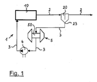
- Figure 1 shows an internal combustion engine 1, which is equipped with an exhaust gas turbocharger 5.
- the exhaust gas turbocharger 5 here has a bearing housing 50, in which leakage oil from the bearing lubrication of the exhaust gas turbocharger 5 collects.
- crankcase ventilation line 2 Connected to the crankcase 10 of the internal combustion engine 1 is a crankcase ventilation line 2 which leads to the right towards an intake tract, not shown here, of the internal combustion engine 1.
- an oil separator 20 is provided in the course of the crankcase ventilation line 2.
- An oil outlet 23 of the oil separator 20 is connected to an oil return line 3.
- the oil return line 3 leads from the oil outlet 23 of the oil separator 20 first into the bearing housing 50 of the exhaust gas turbocharger. 5
- the oil coming from the oil separator 20 is combined with the leakage oil of the exhaust gas turbocharger 5. From the bearing housing 50 then performs a further portion of the oil return line 3 to the crankcase 10 of the internal combustion engine 1. In this second section of the oil return line 3 between the bearing housing 50 and the crankcase 10th an oil conveying device 4 is inserted.
- This oil delivery device 4 is an oil pump, which may have a coupled to the internal combustion engine 1 mechanical drive or a separate drive.
- the oil delivery device 4 In internal combustion engines 1 with an exhaust gas turbocharger 5 or with a compressor, the oil delivery device 4 already exists to suck the accumulating in the bearing housing 50 leakage oil of the exhaust gas turbocharger 5 and to lead into the crankcase 10 of the internal combustion engine 1.
- the oil conveying device 4 which is present anyway for the leakage oil return from the exhaust gas turbocharger 5 is also used for the return of the oil separated from the crankcase ventilation gas in the oil separator 20.
- an additional oil delivery device is not needed; Rather, advantageously in connection with the exhaust gas turbocharger 5 already existing oil delivery device 4 is used to actively promote the oil from the oil separator 20 to the crankcase 10 of the internal combustion engine 1.
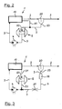
- FIG 2 shows an embodiment of an internal combustion engine 1, in which also an exhaust gas turbocharger 5 is provided. All individual parts, which has the embodiment of Figure 1, also has the embodiment of Figure 2 and reference is made in this regard to the description of the figures for Figure 1.
- a separate ventilation line 51 is provided, which opens from the crankcase 10 of the internal combustion engine 1 into the section of the oil return line 3 lying upstream of the bearing housing 50.
- This embodiment is useful or necessary when no partial flow of the crankcase ventilation gas from the vent line 2 can be diverted through the oil separator 20 and the oil outlet 23, because thereby affects the functions of the oil separator 20 and its efficiency would be unduly reduced. This is the case, for example, when the oil separator 20 is a cyclone separator.
- vent line 51 is gas from the crankcase 10, bypassing the oil separator 20 upstream of the bearing housing 50 in the oil return line 3 and through this further to the bearing housing 50 feasible.
- the ventilation line 51 from the crankcase 10 may also be guided directly into the bearing housing 50 here.
- crankcase ventilation line 2 leads from the crankcase 10 of the internal combustion engine 1 to an intake tract, not shown here, of the internal combustion engine 1, in order to vent the crankcase 10.
- the oil separator 20 is arranged here as well. With the oil outlet 23 of the oil separator 20, the oil return line 3 is also connected here again.
- the internal combustion engine 1 includes an exhaust gas turbocharger 5, which has a bearing housing 50 for collecting oil leakage. Between the crankcase 10 of the internal combustion engine 1 and the bearing housing 50 of the exhaust gas turbocharger 5, a vent line 51 is provided through which crankcase gas from the crankcase 10 in the bearing housing 50 can be guided.
- an oil suction line 53 is further connected, which is brought together at its downstream end with the coming of the oil outlet 23 of the oil separator 20 oil return line 3. Downstream of the merging of the oil return line 3 with the oil suction line 53, the oil feed device 4, again in the form of an oil pump, is provided here. From the oil conveyor 4, a last section of the oil return line 3 leads to the crankcase 10 of the internal combustion engine 1.
- the oil return line 3 bypasses in its portion between the oil outlet 23 of the oil separator 20 and the oil conveyor 4, the bearing housing 50 of the exhaust gas turbocharger 5. Nevertheless, a single oil delivery device 4 is sufficient to both the oil separated in the oil separator 20 from the crankcase ventilation gas as Also, the resulting in the bearing housing 50 of the exhaust gas turbocharger 5 to promote active oil to the crankcase 10 of the internal combustion engine 1.
- a buffer volume 32 is inserted into the oil return line 3 in order to be able to collect oil if required, when the amount of oil deposited in the oil separator 20 exceeds the quantity of oil that can be removed by the oil feed device 4. Since such operating conditions of the internal combustion engine 1 are to be expected only relatively rarely and then only for relatively short periods of time, sufficient for the buffer volume 32 is a relatively small size, which can easily accommodate within the entire device for the separation of oil from the crankcase ventilation gas.
- a throttle 31 serves to the maximum flow of oil or oil and crankcase ventilation gas, which can be removed from the oil separator 20, on to limit a desired value. This is particularly avoided that crankcase ventilation gas in a large extent by the oil outlet 23 of the oil separator 20 from the crankcase ventilation gas flow, which flows through the vent line 2, is branched off.
- the oil delivery device 4 may have a drive with constant power, since this also sufficient function is achieved. If necessary, a drive of the oil delivery device 4 can also be regulated in its performance in order to make a needs-based adjustment can.
- the throttle 31 provided in the example according to FIG. 3 can be adjustable in order to enable control in this way.
Landscapes
- Engineering & Computer Science (AREA)
- Mechanical Engineering (AREA)
- General Engineering & Computer Science (AREA)
- Chemical & Material Sciences (AREA)
- Combustion & Propulsion (AREA)
- Lubrication Details And Ventilation Of Internal Combustion Engines (AREA)
- Supercharger (AREA)
Applications Claiming Priority (1)
| Application Number | Priority Date | Filing Date | Title |
|---|---|---|---|
| DE202005018132U DE202005018132U1 (de) | 2005-11-17 | 2005-11-17 | Brennkraftmaschine mit einer Einrichtung zum Abscheiden von Öl aus dem Kurbelgehäuseentlüftungsgas |
Publications (3)
| Publication Number | Publication Date |
|---|---|
| EP1788206A2 true EP1788206A2 (fr) | 2007-05-23 |
| EP1788206A3 EP1788206A3 (fr) | 2007-12-26 |
| EP1788206B1 EP1788206B1 (fr) | 2009-12-02 |
Family
ID=37561106
Family Applications (1)
| Application Number | Title | Priority Date | Filing Date |
|---|---|---|---|
| EP06022363A Not-in-force EP1788206B1 (fr) | 2005-11-17 | 2006-10-26 | Moteur à combustion interne avec un dispositif pour séparer l'huile du gaz de ventilation |
Country Status (3)
| Country | Link |
|---|---|
| EP (1) | EP1788206B1 (fr) |
| AT (1) | ATE450696T1 (fr) |
| DE (2) | DE202005018132U1 (fr) |
Cited By (4)
| Publication number | Priority date | Publication date | Assignee | Title |
|---|---|---|---|---|
| DE102009051848A1 (de) * | 2009-10-28 | 2011-05-05 | Dr. Ing. H.C. F. Porsche Aktiengesellschaft | Brennkraftmaschine |
| EP3578770A1 (fr) * | 2018-06-04 | 2019-12-11 | Mazda Motor Corporation | Dispositif de blow-by d'un moteur équipé d'un surcompresseur |
| JP2019210930A (ja) * | 2018-06-04 | 2019-12-12 | マツダ株式会社 | 過給機付エンジンのブローバイガス装置 |
| JP2019210847A (ja) * | 2018-06-04 | 2019-12-12 | マツダ株式会社 | 過給機付エンジン |
Families Citing this family (6)
| Publication number | Priority date | Publication date | Assignee | Title |
|---|---|---|---|---|
| DE102007030277A1 (de) * | 2007-06-28 | 2009-01-08 | Mann + Hummel Gmbh | Turbolader für eine Brennkraftmaschine |
| US7699029B2 (en) * | 2007-07-26 | 2010-04-20 | Cummins Filtration Ip, Inc. | Crankcase ventilation system with pumped scavenged oil |
| DE102010009913A1 (de) * | 2010-03-02 | 2011-09-08 | Daimler Ag | Verbrennungskraftmaschine |
| DE102011075933A1 (de) | 2011-05-16 | 2012-11-22 | Bayerische Motoren Werke Aktiengesellschaft | Brennkraftmaschine |
| DE202013008611U1 (de) * | 2013-09-26 | 2014-09-29 | Reinz-Dichtungs-Gmbh | Entlüftungssystem für aufgeladene Brennkraftmaschinen |
| DE102016220658A1 (de) | 2016-10-21 | 2018-04-26 | Bayerische Motoren Werke Aktiengesellschaft | Ölabscheidevorrichtung |
Family Cites Families (14)
| Publication number | Priority date | Publication date | Assignee | Title |
|---|---|---|---|---|
| DE2209909C2 (de) * | 1972-03-02 | 1982-07-22 | Dr.Ing.H.C. F. Porsche Ag, 7000 Stuttgart | Vorrichtung zur Vermeidung von Schmiermittelverlusten bei einem Abgasturbolader, insbesondere bei Brennkraftmaschinen |
| US3978671A (en) * | 1974-10-15 | 1976-09-07 | The Cessna Aircraft Company | Duplex engine oil separator |
| US4480440A (en) * | 1982-04-21 | 1984-11-06 | Wallace Murray Corporation | Turbocharger compressor end ventilation system |
| JPS6047821A (ja) * | 1983-08-24 | 1985-03-15 | Hitachi Ltd | タ−ボ過給機の排油機構 |
| DE8433272U1 (de) * | 1984-11-14 | 1985-05-30 | Wadephul, Jost, Dipl.-Ing., 2150 Buxtehude | Vorrichtung zur verringerung des motoroelverbrauches von oszillierenden verbrennungskraftmaschinen |
| JP2689655B2 (ja) * | 1989-12-05 | 1997-12-10 | 株式会社日本自動車部品総合研究所 | ブローバイガス還元装置 |
| JPH03242411A (ja) * | 1990-02-19 | 1991-10-29 | Aisin Seiki Co Ltd | 内燃機関の気液分離機構 |
| DE4101203A1 (de) * | 1991-01-17 | 1992-07-23 | Bayerische Motoren Werke Ag | Kurbelgehaeuseentlueftung einer brennkraftmaschine |
| DE4431088A1 (de) * | 1994-09-01 | 1996-03-07 | Kloeckner Humboldt Deutz Ag | Ölabsaugung für Abgasturbolader |
| US6092492A (en) * | 1996-08-05 | 2000-07-25 | Motorenfabrik Hatz Gmbh & Co. Kg | Venting device for the crankcase of an internal combustion engine |
| DE19631654A1 (de) * | 1996-08-05 | 1998-02-19 | Hatz Motoren | Entlüftungsvorrichtung für das Kurbelgehäuse einer Brennkraftmaschine |
| DE19913176A1 (de) * | 1999-03-24 | 2000-09-28 | Fev Motorentech Gmbh | Motorblock mit Ölabscheidung im Entlüftungsbereich |
| DE10062483A1 (de) * | 2000-12-14 | 2002-06-20 | Deutz Ag | Filter zur Reinigung von Kurbelgehäuseentlüftungsgasen einer Brennkraftmaschine |
| JP4558984B2 (ja) * | 2001-06-28 | 2010-10-06 | ヤマハ発動機株式会社 | ブローバイガスのセパレータ |
-
2005
- 2005-11-17 DE DE202005018132U patent/DE202005018132U1/de not_active Expired - Lifetime
-
2006
- 2006-10-26 EP EP06022363A patent/EP1788206B1/fr not_active Not-in-force
- 2006-10-26 AT AT06022363T patent/ATE450696T1/de active
- 2006-10-26 DE DE502006005500T patent/DE502006005500D1/de active Active
Cited By (8)
| Publication number | Priority date | Publication date | Assignee | Title |
|---|---|---|---|---|
| DE102009051848A1 (de) * | 2009-10-28 | 2011-05-05 | Dr. Ing. H.C. F. Porsche Aktiengesellschaft | Brennkraftmaschine |
| CN102052145A (zh) * | 2009-10-28 | 2011-05-11 | Dr.Ing.h.c.F.保时捷股份公司 | 内燃发动机 |
| CN102052145B (zh) * | 2009-10-28 | 2013-03-27 | Dr.Ing.h.c.F.保时捷股份公司 | 内燃发动机 |
| US8474259B2 (en) | 2009-10-28 | 2013-07-02 | Dr. Ing. H.C. F. Porsche Aktiengesellschaft | Internal combustion engine |
| EP3578770A1 (fr) * | 2018-06-04 | 2019-12-11 | Mazda Motor Corporation | Dispositif de blow-by d'un moteur équipé d'un surcompresseur |
| JP2019210930A (ja) * | 2018-06-04 | 2019-12-12 | マツダ株式会社 | 過給機付エンジンのブローバイガス装置 |
| JP2019210847A (ja) * | 2018-06-04 | 2019-12-12 | マツダ株式会社 | 過給機付エンジン |
| US10927752B2 (en) * | 2018-06-04 | 2021-02-23 | Mazda Motor Corporation | Blow-by gas device of supercharger-equipped engine |
Also Published As
| Publication number | Publication date |
|---|---|
| DE502006005500D1 (de) | 2010-01-14 |
| EP1788206A3 (fr) | 2007-12-26 |
| ATE450696T1 (de) | 2009-12-15 |
| DE202005018132U1 (de) | 2007-03-29 |
| EP1788206B1 (fr) | 2009-12-02 |
Similar Documents
| Publication | Publication Date | Title |
|---|---|---|
| EP1366272B1 (fr) | Dispositif pour le degazage du carter-cylindres d'un moteur a combustion interne | |
| EP2815089B1 (fr) | Dispositif d'aeration de carter de moteur | |
| EP3020935B1 (fr) | Dispositif de dégazage du carter de vilebrequin | |
| DE102006024816A1 (de) | Einrichtung für die Entlüftung eines Kurbelgehäuses | |
| DE102012220800A1 (de) | Fahrzeug mit Brennkraftmaschine und Kurbelgehäuseentlüftungseinrichtung | |
| EP2057358A2 (fr) | Dispositif d'évacuation d'air du carter moteur | |
| DE10153120A1 (de) | Einrichtung für die Entlüftung des Kurbelgehäuses einer Brennkraftmaschine | |
| EP1788206B1 (fr) | Moteur à combustion interne avec un dispositif pour séparer l'huile du gaz de ventilation | |
| DE102010043060B4 (de) | Kurbelgehäuse und Brennkraftmaschine | |
| DE102014222505A1 (de) | Ölabscheideeinrichtung | |
| EP2313626A1 (fr) | Système turborécupérateur destiné à un dispositif d entraînement | |
| DE102006051143B4 (de) | Adaptiver Ölabscheider | |
| DE102005059668A1 (de) | Brennkraftmaschine | |
| DE102012206650B4 (de) | Turboladeranordnung für einen Verbrennungsmotor | |
| DE102015203337B4 (de) | Brennkraftmaschine und Zylinderkopfhaube | |
| DE19925773B4 (de) | Abgasturbolader mit einem Notöltank | |
| DE102014225817B4 (de) | Entlüftungseinrichtung für eine Brennkraftmaschine sowie Brennkraftmaschine | |
| DE102006017924A1 (de) | Trockensumpfschmierung für eine Brennkraftmaschine sowie Schmieröltank für eine Trockensumpfschmierung | |
| DE102012202405A1 (de) | Fahrzeug | |
| DE102010012118A1 (de) | Verbrennungskraftmaschine | |
| DE102009025535B4 (de) | Schmiermittelpumpe | |
| DE20318633U1 (de) | Einrichtung für die Rück- oder Abführung und die Entölung des Kurbelgehäuse-Entlüftungsgases einer Brennkraftmaschine | |
| EP2525055A2 (fr) | Moteur à combustion interne | |
| DE102005020442B4 (de) | Entlüftungseinrichtung für ein Kurbelgehäuse einer Brennkraftmaschine | |
| DE102016217688A1 (de) | Brennkraftmaschine mit Kurbelgehäuseentlüftungseinrichtung |
Legal Events
| Date | Code | Title | Description |
|---|---|---|---|
| PUAI | Public reference made under article 153(3) epc to a published international application that has entered the european phase |
Free format text: ORIGINAL CODE: 0009012 |
|
| AK | Designated contracting states |
Kind code of ref document: A2 Designated state(s): AT BE BG CH CY CZ DE DK EE ES FI FR GB GR HU IE IS IT LI LT LU LV MC NL PL PT RO SE SI SK TR |
|
| AX | Request for extension of the european patent |
Extension state: AL BA HR MK YU |
|
| PUAL | Search report despatched |
Free format text: ORIGINAL CODE: 0009013 |
|
| AK | Designated contracting states |
Kind code of ref document: A3 Designated state(s): AT BE BG CH CY CZ DE DK EE ES FI FR GB GR HU IE IS IT LI LT LU LV MC NL PL PT RO SE SI SK TR |
|
| AX | Request for extension of the european patent |
Extension state: AL BA HR MK YU |
|
| 17P | Request for examination filed |
Effective date: 20080623 |
|
| AKX | Designation fees paid |
Designated state(s): AT BE BG CH CY CZ DE DK EE ES FI FR GB GR HU IE IS IT LI LT LU LV MC NL PL PT RO SE SI SK TR |
|
| GRAP | Despatch of communication of intention to grant a patent |
Free format text: ORIGINAL CODE: EPIDOSNIGR1 |
|
| GRAC | Information related to communication of intention to grant a patent modified |
Free format text: ORIGINAL CODE: EPIDOSCIGR1 |
|
| GRAC | Information related to communication of intention to grant a patent modified |
Free format text: ORIGINAL CODE: EPIDOSCIGR1 |
|
| GRAS | Grant fee paid |
Free format text: ORIGINAL CODE: EPIDOSNIGR3 |
|
| GRAA | (expected) grant |
Free format text: ORIGINAL CODE: 0009210 |
|
| AK | Designated contracting states |
Kind code of ref document: B1 Designated state(s): AT BE BG CH CY CZ DE DK EE ES FI FR GB GR HU IE IS IT LI LT LU LV MC NL PL PT RO SE SI SK TR |
|
| REG | Reference to a national code |
Ref country code: GB Ref legal event code: FG4D Free format text: NOT ENGLISH |
|
| REG | Reference to a national code |
Ref country code: CH Ref legal event code: EP |
|
| REG | Reference to a national code |
Ref country code: IE Ref legal event code: FG4D |
|
| REF | Corresponds to: |
Ref document number: 502006005500 Country of ref document: DE Date of ref document: 20100114 Kind code of ref document: P |
|
| REG | Reference to a national code |
Ref country code: NL Ref legal event code: VDEP Effective date: 20091202 |
|
| PG25 | Lapsed in a contracting state [announced via postgrant information from national office to epo] |
Ref country code: FI Free format text: LAPSE BECAUSE OF FAILURE TO SUBMIT A TRANSLATION OF THE DESCRIPTION OR TO PAY THE FEE WITHIN THE PRESCRIBED TIME-LIMIT Effective date: 20091202 Ref country code: SE Free format text: LAPSE BECAUSE OF FAILURE TO SUBMIT A TRANSLATION OF THE DESCRIPTION OR TO PAY THE FEE WITHIN THE PRESCRIBED TIME-LIMIT Effective date: 20091202 Ref country code: LT Free format text: LAPSE BECAUSE OF FAILURE TO SUBMIT A TRANSLATION OF THE DESCRIPTION OR TO PAY THE FEE WITHIN THE PRESCRIBED TIME-LIMIT Effective date: 20091202 |
|
| LTIE | Lt: invalidation of european patent or patent extension |
Effective date: 20091202 |
|
| PG25 | Lapsed in a contracting state [announced via postgrant information from national office to epo] |
Ref country code: SI Free format text: LAPSE BECAUSE OF FAILURE TO SUBMIT A TRANSLATION OF THE DESCRIPTION OR TO PAY THE FEE WITHIN THE PRESCRIBED TIME-LIMIT Effective date: 20091202 Ref country code: LV Free format text: LAPSE BECAUSE OF FAILURE TO SUBMIT A TRANSLATION OF THE DESCRIPTION OR TO PAY THE FEE WITHIN THE PRESCRIBED TIME-LIMIT Effective date: 20091202 Ref country code: PL Free format text: LAPSE BECAUSE OF FAILURE TO SUBMIT A TRANSLATION OF THE DESCRIPTION OR TO PAY THE FEE WITHIN THE PRESCRIBED TIME-LIMIT Effective date: 20091202 Ref country code: CY Free format text: LAPSE BECAUSE OF FAILURE TO SUBMIT A TRANSLATION OF THE DESCRIPTION OR TO PAY THE FEE WITHIN THE PRESCRIBED TIME-LIMIT Effective date: 20091202 |
|
| REG | Reference to a national code |
Ref country code: IE Ref legal event code: FD4D |
|
| PG25 | Lapsed in a contracting state [announced via postgrant information from national office to epo] |
Ref country code: IE Free format text: LAPSE BECAUSE OF FAILURE TO SUBMIT A TRANSLATION OF THE DESCRIPTION OR TO PAY THE FEE WITHIN THE PRESCRIBED TIME-LIMIT Effective date: 20091202 Ref country code: ES Free format text: LAPSE BECAUSE OF FAILURE TO SUBMIT A TRANSLATION OF THE DESCRIPTION OR TO PAY THE FEE WITHIN THE PRESCRIBED TIME-LIMIT Effective date: 20100313 Ref country code: IS Free format text: LAPSE BECAUSE OF FAILURE TO SUBMIT A TRANSLATION OF THE DESCRIPTION OR TO PAY THE FEE WITHIN THE PRESCRIBED TIME-LIMIT Effective date: 20100402 Ref country code: RO Free format text: LAPSE BECAUSE OF FAILURE TO SUBMIT A TRANSLATION OF THE DESCRIPTION OR TO PAY THE FEE WITHIN THE PRESCRIBED TIME-LIMIT Effective date: 20091202 Ref country code: NL Free format text: LAPSE BECAUSE OF FAILURE TO SUBMIT A TRANSLATION OF THE DESCRIPTION OR TO PAY THE FEE WITHIN THE PRESCRIBED TIME-LIMIT Effective date: 20091202 Ref country code: BG Free format text: LAPSE BECAUSE OF FAILURE TO SUBMIT A TRANSLATION OF THE DESCRIPTION OR TO PAY THE FEE WITHIN THE PRESCRIBED TIME-LIMIT Effective date: 20100302 Ref country code: PT Free format text: LAPSE BECAUSE OF FAILURE TO SUBMIT A TRANSLATION OF THE DESCRIPTION OR TO PAY THE FEE WITHIN THE PRESCRIBED TIME-LIMIT Effective date: 20100402 Ref country code: EE Free format text: LAPSE BECAUSE OF FAILURE TO SUBMIT A TRANSLATION OF THE DESCRIPTION OR TO PAY THE FEE WITHIN THE PRESCRIBED TIME-LIMIT Effective date: 20091202 |
|
| PG25 | Lapsed in a contracting state [announced via postgrant information from national office to epo] |
Ref country code: SK Free format text: LAPSE BECAUSE OF FAILURE TO SUBMIT A TRANSLATION OF THE DESCRIPTION OR TO PAY THE FEE WITHIN THE PRESCRIBED TIME-LIMIT Effective date: 20091202 Ref country code: CZ Free format text: LAPSE BECAUSE OF FAILURE TO SUBMIT A TRANSLATION OF THE DESCRIPTION OR TO PAY THE FEE WITHIN THE PRESCRIBED TIME-LIMIT Effective date: 20091202 |
|
| PLBE | No opposition filed within time limit |
Free format text: ORIGINAL CODE: 0009261 |
|
| STAA | Information on the status of an ep patent application or granted ep patent |
Free format text: STATUS: NO OPPOSITION FILED WITHIN TIME LIMIT |
|
| PG25 | Lapsed in a contracting state [announced via postgrant information from national office to epo] |
Ref country code: GR Free format text: LAPSE BECAUSE OF FAILURE TO SUBMIT A TRANSLATION OF THE DESCRIPTION OR TO PAY THE FEE WITHIN THE PRESCRIBED TIME-LIMIT Effective date: 20100303 |
|
| 26N | No opposition filed |
Effective date: 20100903 |
|
| PG25 | Lapsed in a contracting state [announced via postgrant information from national office to epo] |
Ref country code: DK Free format text: LAPSE BECAUSE OF FAILURE TO SUBMIT A TRANSLATION OF THE DESCRIPTION OR TO PAY THE FEE WITHIN THE PRESCRIBED TIME-LIMIT Effective date: 20091202 |
|
| PG25 | Lapsed in a contracting state [announced via postgrant information from national office to epo] |
Ref country code: IT Free format text: LAPSE BECAUSE OF FAILURE TO SUBMIT A TRANSLATION OF THE DESCRIPTION OR TO PAY THE FEE WITHIN THE PRESCRIBED TIME-LIMIT Effective date: 20091202 |
|
| BERE | Be: lapsed |
Owner name: HENGST G.M.B.H. & CO. KG Effective date: 20101031 |
|
| PG25 | Lapsed in a contracting state [announced via postgrant information from national office to epo] |
Ref country code: MC Free format text: LAPSE BECAUSE OF NON-PAYMENT OF DUE FEES Effective date: 20101031 |
|
| REG | Reference to a national code |
Ref country code: CH Ref legal event code: PL |
|
| GBPC | Gb: european patent ceased through non-payment of renewal fee |
Effective date: 20101026 |
|
| PG25 | Lapsed in a contracting state [announced via postgrant information from national office to epo] |
Ref country code: CH Free format text: LAPSE BECAUSE OF NON-PAYMENT OF DUE FEES Effective date: 20101031 Ref country code: LI Free format text: LAPSE BECAUSE OF NON-PAYMENT OF DUE FEES Effective date: 20101031 Ref country code: FR Free format text: LAPSE BECAUSE OF NON-PAYMENT OF DUE FEES Effective date: 20101102 |
|
| REG | Reference to a national code |
Ref country code: FR Ref legal event code: ST Effective date: 20110630 |
|
| PG25 | Lapsed in a contracting state [announced via postgrant information from national office to epo] |
Ref country code: GB Free format text: LAPSE BECAUSE OF NON-PAYMENT OF DUE FEES Effective date: 20101026 Ref country code: BE Free format text: LAPSE BECAUSE OF NON-PAYMENT OF DUE FEES Effective date: 20101031 |
|
| PG25 | Lapsed in a contracting state [announced via postgrant information from national office to epo] |
Ref country code: HU Free format text: LAPSE BECAUSE OF FAILURE TO SUBMIT A TRANSLATION OF THE DESCRIPTION OR TO PAY THE FEE WITHIN THE PRESCRIBED TIME-LIMIT Effective date: 20100603 Ref country code: LU Free format text: LAPSE BECAUSE OF NON-PAYMENT OF DUE FEES Effective date: 20101026 |
|
| PG25 | Lapsed in a contracting state [announced via postgrant information from national office to epo] |
Ref country code: TR Free format text: LAPSE BECAUSE OF FAILURE TO SUBMIT A TRANSLATION OF THE DESCRIPTION OR TO PAY THE FEE WITHIN THE PRESCRIBED TIME-LIMIT Effective date: 20091202 |
|
| REG | Reference to a national code |
Ref country code: AT Ref legal event code: MM01 Ref document number: 450696 Country of ref document: AT Kind code of ref document: T Effective date: 20111026 |
|
| PG25 | Lapsed in a contracting state [announced via postgrant information from national office to epo] |
Ref country code: AT Free format text: LAPSE BECAUSE OF NON-PAYMENT OF DUE FEES Effective date: 20111026 |
|
| PGFP | Annual fee paid to national office [announced via postgrant information from national office to epo] |
Ref country code: DE Payment date: 20161219 Year of fee payment: 11 |
|
| REG | Reference to a national code |
Ref country code: DE Ref legal event code: R082 Ref document number: 502006005500 Country of ref document: DE Representative=s name: SCHULZE HORN & PARTNER GBR, DE Ref country code: DE Ref legal event code: R081 Ref document number: 502006005500 Country of ref document: DE Owner name: HENGST SE, DE Free format text: FORMER OWNER: HENGST GMBH & CO. KG, 48147 MUENSTER, DE |
|
| REG | Reference to a national code |
Ref country code: DE Ref legal event code: R081 Ref document number: 502006005500 Country of ref document: DE Owner name: HENGST SE, DE Free format text: FORMER OWNER: HENGST SE & CO. KG, 48147 MUENSTER, DE Ref country code: DE Ref legal event code: R082 Ref document number: 502006005500 Country of ref document: DE Representative=s name: SCHULZE HORN & PARTNER GBR, DE |
|
| REG | Reference to a national code |
Ref country code: DE Ref legal event code: R119 Ref document number: 502006005500 Country of ref document: DE |
|
| PG25 | Lapsed in a contracting state [announced via postgrant information from national office to epo] |
Ref country code: DE Free format text: LAPSE BECAUSE OF NON-PAYMENT OF DUE FEES Effective date: 20180501 |