EP1788334A2 - Echangeur de chaleur - Google Patents
Echangeur de chaleur Download PDFInfo
- Publication number
- EP1788334A2 EP1788334A2 EP20060023813 EP06023813A EP1788334A2 EP 1788334 A2 EP1788334 A2 EP 1788334A2 EP 20060023813 EP20060023813 EP 20060023813 EP 06023813 A EP06023813 A EP 06023813A EP 1788334 A2 EP1788334 A2 EP 1788334A2
- Authority
- EP
- European Patent Office
- Prior art keywords
- heat exchanger
- exchanger according
- plug
- shoe
- halves
- Prior art date
- Legal status (The legal status is an assumption and is not a legal conclusion. Google has not performed a legal analysis and makes no representation as to the accuracy of the status listed.)
- Withdrawn
Links
- 238000007599 discharging Methods 0.000 claims abstract description 4
- 238000005452 bending Methods 0.000 claims description 17
- 238000010276 construction Methods 0.000 claims description 2
- 239000012530 fluid Substances 0.000 description 12
- 238000004519 manufacturing process Methods 0.000 description 7
- 229910052751 metal Inorganic materials 0.000 description 4
- 239000002184 metal Substances 0.000 description 4
- 244000089486 Phragmites australis subsp australis Species 0.000 description 3
- 238000000926 separation method Methods 0.000 description 3
- 125000006850 spacer group Chemical group 0.000 description 3
- 229910052782 aluminium Inorganic materials 0.000 description 2
- XAGFODPZIPBFFR-UHFFFAOYSA-N aluminium Chemical compound [Al] XAGFODPZIPBFFR-UHFFFAOYSA-N 0.000 description 2
- 238000004080 punching Methods 0.000 description 2
- 238000004891 communication Methods 0.000 description 1
- 239000002826 coolant Substances 0.000 description 1
- 238000003780 insertion Methods 0.000 description 1
- 230000037431 insertion Effects 0.000 description 1
- 230000013011 mating Effects 0.000 description 1
- 238000000034 method Methods 0.000 description 1
- 239000010705 motor oil Substances 0.000 description 1
- 239000003921 oil Substances 0.000 description 1
- 238000005476 soldering Methods 0.000 description 1
Images


Classifications
-
- F—MECHANICAL ENGINEERING; LIGHTING; HEATING; WEAPONS; BLASTING
- F28—HEAT EXCHANGE IN GENERAL
- F28D—HEAT-EXCHANGE APPARATUS, NOT PROVIDED FOR IN ANOTHER SUBCLASS, IN WHICH THE HEAT-EXCHANGE MEDIA DO NOT COME INTO DIRECT CONTACT
- F28D1/00—Heat-exchange apparatus having stationary conduit assemblies for one heat-exchange medium only, the media being in contact with different sides of the conduit wall, in which the other heat-exchange medium is a large body of fluid, e.g. domestic or motor car radiators
- F28D1/02—Heat-exchange apparatus having stationary conduit assemblies for one heat-exchange medium only, the media being in contact with different sides of the conduit wall, in which the other heat-exchange medium is a large body of fluid, e.g. domestic or motor car radiators with heat-exchange conduits immersed in the body of fluid
- F28D1/04—Heat-exchange apparatus having stationary conduit assemblies for one heat-exchange medium only, the media being in contact with different sides of the conduit wall, in which the other heat-exchange medium is a large body of fluid, e.g. domestic or motor car radiators with heat-exchange conduits immersed in the body of fluid with tubular conduits
- F28D1/053—Heat-exchange apparatus having stationary conduit assemblies for one heat-exchange medium only, the media being in contact with different sides of the conduit wall, in which the other heat-exchange medium is a large body of fluid, e.g. domestic or motor car radiators with heat-exchange conduits immersed in the body of fluid with tubular conduits the conduits being straight
- F28D1/0535—Heat-exchange apparatus having stationary conduit assemblies for one heat-exchange medium only, the media being in contact with different sides of the conduit wall, in which the other heat-exchange medium is a large body of fluid, e.g. domestic or motor car radiators with heat-exchange conduits immersed in the body of fluid with tubular conduits the conduits being straight the conduits having a non-circular cross-section
- F28D1/05358—Assemblies of conduits connected side by side or with individual headers, e.g. section type radiators
-
- F—MECHANICAL ENGINEERING; LIGHTING; HEATING; WEAPONS; BLASTING
- F28—HEAT EXCHANGE IN GENERAL
- F28F—DETAILS OF HEAT-EXCHANGE AND HEAT-TRANSFER APPARATUS, OF GENERAL APPLICATION
- F28F9/00—Casings; Header boxes; Auxiliary supports for elements; Auxiliary members within casings
- F28F9/02—Header boxes; End plates
- F28F9/0219—Arrangements for sealing end plates into casing or header box; Header box sub-elements
- F28F9/0221—Header boxes or end plates formed by stacked elements
Definitions
- the invention relates to a heat exchanger, in particular for a motor vehicle, with a plurality of stacked and interconnected conduit means, in particular flat tubes, each having at their ends a through hole for supplying or discharging a medium.
- a heat exchanger which has a collecting tube, in which at least one slot is introduced, which lies in a plane approximately perpendicular to the longitudinal axis of the collecting tube, in the slot, a fluid flow-through flat tube can be inserted.
- DE 44 14 979 A1 is a constructed of flat tubes heat exchanger known which has a comb-like connection block with receiving slots for the flat tubes.
- the object of the invention is to provide a stable heat exchanger according to the preamble of claim 1, which is simple in construction and inexpensive to produce.
- the object is in a heat exchanger, in particular for a motor vehicle, with a plurality of stacked and interconnected conduit means, in particular flat tubes, at their ends respectively a through hole for supplying or discharging a medium, achieved in that the Kauss esters are each received in a plug-in shoe.
- a plug-in shoe important for the internal pressure resistance Kirs Rheinsend Scheme is enhanced.
- a preferred embodiment of the heat exchanger is characterized in that a plurality of patch shoes are stacked one above the other.
- the patch shoes replace the manifolds used in conventional heat exchangers to receive the conduit ends.
- a further preferred embodiment of the heat exchanger is characterized in that the plug-in shoe is embossed from a stamped part. As a result, the production costs can be kept low.
- a further preferred embodiment of the heat exchanger is characterized in that the plug-in shoe is integrally formed from two halves which are interconnected by a preferably extending in the transverse direction of the conduit means bending edge or bending line.
- the plug shoe is formed by a substantially rectangular plate which is divided by the bending edge or bending line into two substantially rectangular halves which are folded together.
- the plate is preferably formed of sheet metal, in particular aluminum sheet.
- a further preferred embodiment of the heat exchanger is characterized in that the two plug shoe halves have a recessed edge region, with which the plug shoe halves abut each other.
- the male shoe halves are soldered together at their edge regions.
- a further preferred embodiment of the heat exchanger is characterized in that the recessed edge regions delimit a trough-shaped receiving space for a line device end.
- the trough-shaped receiving space is open at one end and surrounds the associated conduit end.
- the plug-in shoe has two through-holes, which are arranged concentrically to each other.
- the through holes allow the inlet or outlet of the medium in the associated conduit means.
- a further preferred embodiment of the heat exchanger is characterized in that the edge regions of the through holes are raised and each have substantially the shape of a cup having a bottom, in which the associated through hole is recessed.
- the boot takes on the function of a spacer between two conduit devices.
- a further preferred embodiment of the heat exchanger is characterized in that a plurality of line devices, in particular flat tubes, are arranged side by side. As a result, the production of multi-row heat exchangers is made possible in a simple manner.
- a further preferred embodiment of the heat exchanger is characterized in that two conduit means, in particular flat tubes, are arranged side by side. As a result, the production of double-row heat exchangers is made possible in a simple manner.
- a further preferred exemplary embodiment of the heat exchanger is characterized in that the line device ends of at least two line devices arranged side by side, in particular flat tubes, are each received in a multiple plug-in shoe. This simplifies pre-assembly.
- a further preferred embodiment of the heat exchanger is characterized in that a plurality of multiple plug-in shoes are stacked one above the other.
- the multiple sockets replace the headers used in conventional heat exchangers to receive the conduit ends.
- Another preferred embodiment of the heat exchanger is characterized in that the Mehrfachsteckschuh is stamped from a stamped part. As a result, the production costs can be kept low.
- a further preferred embodiment of the heat exchanger is characterized in that the Mehrfachsteckschuh is integrally formed of two halves, which are interconnected by a running in the transverse direction of the Kirsrichtraumsend bending edge or bending line. As a result, the assembly of the heat exchanger according to the invention is simplified.
- a further preferred embodiment of the heat exchanger is characterized in that the Mehrfachsteckschuh has a plurality of separate receiving areas for each one line device end. Depending on the application, the recording areas may also be in communication with each other.
- a further preferred embodiment of the heat exchanger is characterized in that the receiving areas for each one line device end are separated by a separation region in which the two halves from which the Mehrfachsteckschuh is integrally formed, are tightly interconnected.
- the two halves are in the separation region preferably cohesively, for example, by soldering, tightly interconnected.
- a further preferred embodiment of the heat exchanger is characterized in that the Mehrfachsteckschuh is formed by a substantially rectangular plate, which is divided by the bending edge or bending line in two substantially rectangular halves, the folded up.
- the plate is preferably formed of sheet metal, in particular aluminum sheet.
- a further preferred embodiment of the heat exchanger is characterized in that the two Mehrfachsteckschuhhquen recessed edge regions which, at least partially, extend around the receiving areas around and with which the Mehrfachsteckschuhhquen abut each other.
- the Mehrfachsteckschuhhbankn are soldered together at their edge regions.
- a further preferred embodiment of the heat exchanger is characterized in that the recessed edge regions each delimit a trough-shaped receiving space for a line device end.
- the trough-shaped receiving spaces are open at one end and embrace the associated conduit end.
- a further preferred embodiment of the heat exchanger is characterized in that the Mehrfachsteckschuh in each receiving area has two through holes, which are arranged concentrically to each other. The through holes allow the inlet or outlet of the medium in the associated conduit means.
- a further preferred embodiment of the heat exchanger is characterized in that the edge regions of the through holes are raised and each have substantially the shape of a cup having a bottom, in which the associated through hole is recessed.
- the Mehrfachsteckschuh assumes the function of a spacer between two conduit means, both between two side by side and, together with another Mehrfachsteckschuh, between two superimposed Leftungs wornen.
- a further preferred embodiment of the heat exchanger is characterized in that a plurality of line devices are stacked on top of each other, and that between two line devices each one Guide is arranged.
- the guide devices are preferably air guide devices, each of which comprises a plurality of air guide ribs.
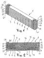
- an oil-air cooler 1 is shown in perspective.
- the oil-air cooler 1 comprises seven flat tubes 3 to 9, which are arranged one above the other.
- the ends of the flat tubes 3 to 9 are each received in a Einsteckschuh 11 to 17, 21 to 27.
- the oil-air cooler 1 of Figure 1 is shown in longitudinal section.
- the Einsteck dilemma 11 to 17, 21 to 27 are arranged one above the other in two stacks.
- the Einsteck dilemma are the Flat tubes arranged parallel to each other.
- the slip-on shoes serve as spacers.
- an air guide 31 to 36 is arranged in each case.
- the flat tube 3 can also be replaced by a base plate, which closes the radiator 1 down.
- the flat tube 9 can be replaced by a cover plate, which closes the radiator 1 upwards.
- the flat tubes 3 to 9 have at their ends in each case at least one opening through which a medium to be cooled, in particular engine oil, can enter or exit.
- the flat tubes 3 to 9 are flowed through in the longitudinal direction of the medium to be cooled.
- the flat tubes 3 to 9 are acted upon by a coolant, preferably with air, which flows around the flat tubes 3 to 9 perpendicular to the plane of the drawing in FIG.
- FIGS. 3 to 5 show a push-fit shoe 41 in the unfolded state.
- the insertion shoe 41 is formed by a substantially rectangular plate 42 made of sheet metal.
- the plate 42 is divided by a bend line 48 into two halves 44 and 45, which are also referred to as flanks.
- the two halves 44, 45 each have substantially the shape of a rectangle.
- the halves 44, 45 have a recessed edge region 51, 52 on three of its sides.
- the halves 44, 45 each have a raised, cup-shaped region 55, 56.
- the cup-shaped region 55, 56 is in each case provided with a central through-hole 61, 62.
- the upper side of the cup-shaped region 55, 56 is arranged at a distance 64 to the upper side of the plate 42.
- the two halves 44, 45 of the Einsteckschuhs 41 are pivotable about the bending line 48.
- the two halves 44, 45 are arranged at an angle of 90 degrees to one another.
- the two halves 44, 45 are each pivoted by 45 degrees relative to the unfolded position illustrated in FIGS. 3 to 5, in which the two halves 44, 45 are arranged in one plane.
- the recessed edge regions 51, 52 of the two halves 44, 45 abut each other.
- the raised areas 55, 56 are then turned away from each other.
- the through holes 61, 62 are then arranged in alignment.
- FIG. 8 shows a push-fit shoe 41 in the folded-up state.
- a flat tube 70 is shown in perspective in Figure 8, which has two ends 71, 72.
- the end 71 of the flat tube 70 has two through holes 74, 75, which are arranged concentrically in the top and the bottom of the flat tube 70.
- the flat tube 70 is, for example, a welded tube with an inserted turbulence insert.
- the through holes 74, 75 are punched into the flat tube 70 on both sides.
- a plug-in shoe 41, 81 is pushed onto the flat tube 70 on both sides.
- the patch shoes 41, 81 are formed from embossed sheet metal parts, which are produced by a bending process.
- the slip-on shoes or slip-in shoes according to the invention reinforce the tube end region, which is important for the internal pressure resistance.
- the block height is defined by the length of the pipe.
- the block width can be easily changed by the number of tubes. By changing the cup height on the patch shoes, other rib widths can be used.
- FIG. 10 shows a conventional oil-air cooler 90 with a plurality of tubes 91, 92 stacked one above the other.
- the tubes 91, 92 are received in a box 93 and open into side parts 94, 95.
- the side parts 94, 95 serve to position the tubes 91, 92 relative to each other.
- On the side parts 94, 95 a collecting box 97, 98 is placed in each case.
- the box 93 is closed by a bottom 99.
- Between the tubes 91, 92 guide means are arranged in the form of ribs.
- the manufacture of the radiator 90 shown in FIG. 10 is relatively complicated and expensive.
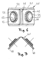
- a Mehrfachsteckschuh 110 is shown in perspective.
- the multiple plug shoe 110 comprises a lower half 111 and an upper half 112.
- the two halves 111 and 112 are formed the same and are formed by punching a rectangular plate, which is folded after punching along a bending line 114.
- the Mehrfachsteckschuh 110 has two receiving areas 116, 117.
- the receiving areas 116, 117 each delimit a trough-shaped receiving space for an associated pipe end.
- a separation region 119 is formed between the two receiving areas 116, 117.
- the two halves 111, 112 are connected to one another in a material-locking manner.
- the Mehrstecksteckschuh 110 further includes recessed edge portions 121, 122, in which the two halves 111, 112 are soldered together.
- the multiple plug shoe has two through holes 124, 125 in each receiving area 116, 117. In the region of the through holes 124, 125, the associated half 111, 112 is deformed to a cup 127, in the bottom 128 of the associated through hole 124 is recessed.
- FIGS. 12 to 14 show two flat tubes 131, 132 in different views, the ends of which are accommodated in two plug-in shoes 110, 130.
- the flat tubes 131, 132 are positioned relative to each other.
- the flat tubes 131, 132 which are connected to one another by the multiple plug-in shoes 110, 130 are also referred to as a double-row tube.
- FIGS. 15 to 17 a heat exchanger according to the invention, in particular a cooler according to the invention, is shown in different views.
- a plurality of pairs of flat tubes 132, 141 to 145 are stacked on top of each other.
- the individual flat tubes are positioned by the Mehrfachsteck dich both side by side and on top of each other.
- the Mehrfachsteck dich 130, 133 to 137 are arranged on one side so that the receiving areas are connected by stacked Mehrfachsteck dichn over the through holes with each other.
- the heat exchanger is closed by a side part 148.
- the heat exchanger is closed by a side part 149.
- the lower side part 148 is integrally connected with end walls 151, 152.
- the end wall 151 closes the lower through holes of the multiple plug shoe 137.
- the end wall 152 closes the lower through holes of the multi-plug shoe above.
- On the top multiple plug-in shoe 133 each have a manifold 154, 155 is arranged. Through the headers 154, 155, a fluid to be cooled is supplied to the heat exchanger or removed. Between the individual flat tubes guiding devices 157 are arranged in the form of corrugated ribs.
- FIG. 18 shows in simplified form a heat exchanger according to the invention with two pipe blocks 161, 162.
- an arrow 164 the incoming fluid is indicated.
- An arrow 165 indicates that the entering fluid 164 simply flows through the heat exchanger block 162.
- arrow 166 the exiting fluid is indicated.
- the flow indicated by the arrows 164 to 166 of the tube block 162 is also referred to as I-flow flow.
- the tube block 161 is flowed through in the same way as the tube block 162.
- two tube blocks 171, 172 are shown in simplified form.
- the fluid entering the pipe blocks 171, 172 is indicated.
- the fluid in the tube blocks 171, 172 is deflected once.
- the exiting fluid is indicated by arrows 178; 188 indicated.
- the two pipe blocks 171, 172 are each flowed through in a U-shape and are therefore also referred to as U-flow pipe blocks.
- the incoming fluid is indicated by an arrow 194.
- an arrow 195 is indicated that the tube block 191 is simply flowed through.
- An arrow 196 indicates that the fluid emerging from the tube block 191 is supplied to the tube block 192. This fluid then flows through the tube block 192, as indicated by an arrow 197.
- the exiting fluid is indicated by an arrow 198.
- the interconnections illustrated in FIGS. 18 to 20 can be realized in a simple manner with multiple slip-on shoes, as shown in FIGS. 11 to 17 and in the installed state.
- the heat exchanger according to the invention provides, inter alia, the following advantages: Illustration of a cost-effective oil / air cooler; Representing a high-strength cooler with a high power density; Depicting a chiller for universal block dimensions; Use of identical parts in the manufacturing process; simple representation of different deflections in the block width / depth; Cost advantage through standardized items; variable block dimensions possible with only one pipe depth; variable connection possibility.
Landscapes
- Engineering & Computer Science (AREA)
- Physics & Mathematics (AREA)
- Thermal Sciences (AREA)
- Mechanical Engineering (AREA)
- General Engineering & Computer Science (AREA)
- Heat-Exchange Devices With Radiators And Conduit Assemblies (AREA)
Applications Claiming Priority (1)
| Application Number | Priority Date | Filing Date | Title |
|---|---|---|---|
| DE102005054730 | 2005-11-17 |
Publications (2)
| Publication Number | Publication Date |
|---|---|
| EP1788334A2 true EP1788334A2 (fr) | 2007-05-23 |
| EP1788334A3 EP1788334A3 (fr) | 2009-04-08 |
Family
ID=37744120
Family Applications (1)
| Application Number | Title | Priority Date | Filing Date |
|---|---|---|---|
| EP20060023813 Withdrawn EP1788334A3 (fr) | 2005-11-17 | 2006-11-16 | Echangeur de chaleur |
Country Status (1)
| Country | Link |
|---|---|
| EP (1) | EP1788334A3 (fr) |
Cited By (1)
| Publication number | Priority date | Publication date | Assignee | Title |
|---|---|---|---|---|
| EP2336697A3 (fr) * | 2009-12-14 | 2015-02-18 | Behr GmbH & Co. KG | Echangeur thermique avec des éléments extrudés et empilés |
Family Cites Families (5)
| Publication number | Priority date | Publication date | Assignee | Title |
|---|---|---|---|---|
| US4846268A (en) * | 1988-01-12 | 1989-07-11 | Thermag Industries Inc. | Heat exchanger with individual twinplate headers |
| FR2834336B1 (fr) * | 2001-12-28 | 2006-12-01 | Valeo Thermique Moteur Sa | Element de circuit pour echangeur de chaleur, notamment de vehicule automobile et echangeur de chaleur ainsi obtenu |
| FR2858399B1 (fr) * | 2003-07-29 | 2005-10-28 | Valeo Thermique Moteur Sa | Embout de tube pour element de circuit hydraulique, en particulier pour echangeur de chaleur |
| FR2860288B1 (fr) * | 2003-09-26 | 2005-11-11 | Valeo Thermique Moteur Sa | Element de circuit pour echangeur de chaleur, et echangeur de chaleur ainsi obtenu |
| FR2864215B1 (fr) * | 2003-12-19 | 2011-07-15 | Valeo Climatisation | Element de circuit pour echangeur de chaleur |
-
2006
- 2006-11-16 EP EP20060023813 patent/EP1788334A3/fr not_active Withdrawn
Non-Patent Citations (1)
| Title |
|---|
| None * |
Cited By (1)
| Publication number | Priority date | Publication date | Assignee | Title |
|---|---|---|---|---|
| EP2336697A3 (fr) * | 2009-12-14 | 2015-02-18 | Behr GmbH & Co. KG | Echangeur thermique avec des éléments extrudés et empilés |
Also Published As
| Publication number | Publication date |
|---|---|
| EP1788334A3 (fr) | 2009-04-08 |
Similar Documents
| Publication | Publication Date | Title |
|---|---|---|
| EP2150757B1 (fr) | Échangeur de chaleur | |
| DE102012006346B4 (de) | Wärmetauscher | |
| DE10056074B4 (de) | Wärmeübertrager | |
| EP2906893B1 (fr) | Échangeur thermique | |
| DE60117693T2 (de) | Wärmetauscher, insbesondere als Kraftstoffkühler bei Brennkraftmaschinen von Kraftfahrzeugen | |
| DE59310250T2 (de) | Plattenwärmetauscher | |
| DE69315281T2 (de) | Plattenwärmetauscher und Verfahren zu dessen Herstellung | |
| EP1273864B1 (fr) | Echangeur de chaleur | |
| EP1701125A2 (fr) | Echangeur de chaleur à tubes plats et tube plat pour échangeur de chaleur | |
| WO2003054467A1 (fr) | Echangeur thermique notamment destine a un vehicule | |
| EP2962056B1 (fr) | Échangeur de chaleur | |
| DE102011079091A1 (de) | Sammler für ein Kühlfluid und Wärmetauscher | |
| DE112016000793T5 (de) | Flexible Bauweise von Wärmetauschern zum Erwärmen und/oder Kühlen von Flüssigkeiten | |
| DE19543234A1 (de) | Lamellen-Wärmetauscher | |
| DE102004002252B4 (de) | Wärmeübertrager für Fahrzeuge | |
| DE102011080499A1 (de) | Wärmeübertrager für ein Fahrzeug und Verfahren zum Herstellen eines Wärmeübertragers für ein Fahrzeug | |
| DE10393269B4 (de) | Kühlvorrichtung für ein motorisiertes Fahrzeug | |
| DE102008036614A1 (de) | Wärmetauscher | |
| DE102010040983A1 (de) | Gaskühler | |
| EP2336697B1 (fr) | Echangeur thermique avec des éléments extrudés et empilés | |
| DE102006054460A1 (de) | Wärmetauscher | |
| EP2049859B1 (fr) | Climatisation pour véhicule à moteur | |
| DE19830846B4 (de) | Wärmetauscher | |
| DE102009056274A1 (de) | Wärmetauscher | |
| DE102015000385A1 (de) | Wärmetauscher, insbesondere zum Aufnehmen von Erdwärme |
Legal Events
| Date | Code | Title | Description |
|---|---|---|---|
| PUAI | Public reference made under article 153(3) epc to a published international application that has entered the european phase |
Free format text: ORIGINAL CODE: 0009012 |
|
| AK | Designated contracting states |
Kind code of ref document: A2 Designated state(s): AT BE BG CH CY CZ DE DK EE ES FI FR GB GR HU IE IS IT LI LT LU LV MC NL PL PT RO SE SI SK TR |
|
| AX | Request for extension of the european patent |
Extension state: AL BA HR MK YU |
|
| PUAL | Search report despatched |
Free format text: ORIGINAL CODE: 0009013 |
|
| AK | Designated contracting states |
Kind code of ref document: A3 Designated state(s): AT BE BG CH CY CZ DE DK EE ES FI FR GB GR HU IE IS IT LI LT LU LV MC NL PL PT RO SE SI SK TR |
|
| AX | Request for extension of the european patent |
Extension state: AL BA HR MK RS |
|
| 17P | Request for examination filed |
Effective date: 20091008 |
|
| 17Q | First examination report despatched |
Effective date: 20091104 |
|
| AKX | Designation fees paid |
Designated state(s): AT BE BG CH CY CZ DE DK EE ES FI FR GB GR HU IE IS IT LI LT LU LV MC NL PL PT RO SE SI SK TR |
|
| RAP1 | Party data changed (applicant data changed or rights of an application transferred) |
Owner name: MAHLE BEHR GMBH & CO. KG |
|
| GRAP | Despatch of communication of intention to grant a patent |
Free format text: ORIGINAL CODE: EPIDOSNIGR1 |
|
| RIC1 | Information provided on ipc code assigned before grant |
Ipc: F28F 9/02 20060101ALI20180404BHEP Ipc: F28D 1/053 20060101AFI20180404BHEP |
|
| INTG | Intention to grant announced |
Effective date: 20180420 |
|
| STAA | Information on the status of an ep patent application or granted ep patent |
Free format text: STATUS: THE APPLICATION IS DEEMED TO BE WITHDRAWN |
|
| 18D | Application deemed to be withdrawn |
Effective date: 20180831 |