EP1788668A2 - Verbinder in dünner Bauweise - Google Patents
Verbinder in dünner Bauweise Download PDFInfo
- Publication number
- EP1788668A2 EP1788668A2 EP07004923A EP07004923A EP1788668A2 EP 1788668 A2 EP1788668 A2 EP 1788668A2 EP 07004923 A EP07004923 A EP 07004923A EP 07004923 A EP07004923 A EP 07004923A EP 1788668 A2 EP1788668 A2 EP 1788668A2
- Authority
- EP
- European Patent Office
- Prior art keywords
- connector
- along
- terminals
- transversal
- transversal direction
- Prior art date
- Legal status (The legal status is an assumption and is not a legal conclusion. Google has not performed a legal analysis and makes no representation as to the accuracy of the status listed.)
- Withdrawn
Links
Images

Classifications
-
- H—ELECTRICITY
- H01—ELECTRIC ELEMENTS
- H01R—ELECTRICALLY-CONDUCTIVE CONNECTIONS; STRUCTURAL ASSOCIATIONS OF A PLURALITY OF MUTUALLY-INSULATED ELECTRICAL CONNECTING ELEMENTS; COUPLING DEVICES; CURRENT COLLECTORS
- H01R13/00—Details of coupling devices of the kinds covered by groups H01R12/70 or H01R24/00 - H01R33/00
- H01R13/648—Protective earth or shield arrangements on coupling devices, e.g. anti-static shielding
- H01R13/658—High frequency shielding arrangements, e.g. against EMI [Electro-Magnetic Interference] or EMP [Electro-Magnetic Pulse]
- H01R13/6581—Shield structure
-
- H—ELECTRICITY
- H01—ELECTRIC ELEMENTS
- H01R—ELECTRICALLY-CONDUCTIVE CONNECTIONS; STRUCTURAL ASSOCIATIONS OF A PLURALITY OF MUTUALLY-INSULATED ELECTRICAL CONNECTING ELEMENTS; COUPLING DEVICES; CURRENT COLLECTORS
- H01R13/00—Details of coupling devices of the kinds covered by groups H01R12/70 or H01R24/00 - H01R33/00
- H01R13/02—Contact members
- H01R13/22—Contacts for co-operating by abutting
- H01R13/24—Contacts for co-operating by abutting resilient; resiliently-mounted
- H01R13/2407—Contacts for co-operating by abutting resilient; resiliently-mounted characterized by the resilient means
- H01R13/2428—Contacts for co-operating by abutting resilient; resiliently-mounted characterized by the resilient means using meander springs
-
- H—ELECTRICITY
- H01—ELECTRIC ELEMENTS
- H01R—ELECTRICALLY-CONDUCTIVE CONNECTIONS; STRUCTURAL ASSOCIATIONS OF A PLURALITY OF MUTUALLY-INSULATED ELECTRICAL CONNECTING ELEMENTS; COUPLING DEVICES; CURRENT COLLECTORS
- H01R13/00—Details of coupling devices of the kinds covered by groups H01R12/70 or H01R24/00 - H01R33/00
- H01R13/02—Contact members
- H01R13/22—Contacts for co-operating by abutting
- H01R13/24—Contacts for co-operating by abutting resilient; resiliently-mounted
-
- H—ELECTRICITY
- H01—ELECTRIC ELEMENTS
- H01R—ELECTRICALLY-CONDUCTIVE CONNECTIONS; STRUCTURAL ASSOCIATIONS OF A PLURALITY OF MUTUALLY-INSULATED ELECTRICAL CONNECTING ELEMENTS; COUPLING DEVICES; CURRENT COLLECTORS
- H01R13/00—Details of coupling devices of the kinds covered by groups H01R12/70 or H01R24/00 - H01R33/00
- H01R13/648—Protective earth or shield arrangements on coupling devices, e.g. anti-static shielding
- H01R13/658—High frequency shielding arrangements, e.g. against EMI [Electro-Magnetic Interference] or EMP [Electro-Magnetic Pulse]
- H01R13/6591—Specific features or arrangements of connection of shield to conductive members
- H01R13/6592—Specific features or arrangements of connection of shield to conductive members the conductive member being a shielded cable
Definitions
- the present invention relates to a connector for connection to a complementary connector along a longitudinal connecting direction, said connector comprising,
- Such a connector is for example disclosed in EP-1 220 370 .
- the outer housing fully surrounds the shield.
- the object of the invention is to solve this problem by providing a connector which can be thinner.
- the invention relates to a connector according to claim 1.
- the invention may comprise one or several of the features recited in the dependent claims.
- the invention also relates to a connection assembly according to claim 10.
- Figures 1 and 2 show a connector or plug 1, such as an input/output plug for a mobile telephone, suitable for connection to a complementary connector or receptacle 2 (only shown on figure 2) along a longitudinal connecting direction LD depicted by a dotted line.
- a connector or plug 1 such as an input/output plug for a mobile telephone
- the connector 1 comprises an outer housing 20 having, in this particular embodiment, of a lower or bottom part 3 and an upper part or cover 4.
- the connector further comprises an electrically insulating body 5 made of an electrically insulating thermoplastic material and is placed inside a shield 6.
- the shield can be made of folded metal sheets. The shield 6 is placed within the outer housing 20.
- the shield 6 comprises a lower part 6a and an upper part 6b.
- the shield 6 surrounds or covers the insulating body 5.
- the insulating body 5 is provided with a plurality of terminals 7 arranged in a row.
- the terminals 7 project forwardly from the insulating body 5 along the longitudinal direction LD.
- the terminals 7 are electrically connected to respective wires (not shown) of a cable 8, whereas the shield 6 is electrically connected to a braid (not shown) of the cable 8, which braid surrounds and thus shields said wires.
- a strain relieving element 9 (overmoulded bushing) is provided in the rear of the outer housing so as to avoid excessive forces on the (solder) connection between the terminals 7 and the wires when the cable 8 is being bent.
- the strain relieve 9 is angled and offset with respect to the longitudinal direction LD.
- the insulating body 5 is provided with two substantially parallel pegs 10, 10', for aligning and polarizing the connector 1 with respect to connector 2.
- Peg 10, 10' includes a latch 11, 11', respectively, for establishing a secure mechanical connection between the connector 1 and the complementary connector 2.
- Buttons 15, 15' provided on the bottom 3 to control the latches 11, 11' to release the mechanical connection between the connector 1 and the connector 2.
- EP-1 220 370 For further details on the connector 1 and the complementary connector 2, one may refer to EP-1 220 370 .
- the outer housing 20 has a general planar shape with a thickness T1 along a first transversal direction TD 1 lower than its thickness T2 along a second transversal direction TD2.
- Directions TD1 and TD2 are perpendicular to the longitudinal direction LD and are perpendicular one with another.
- the outer housing 20 exhibits two major opposing side walls 17 and 19 facing outwardly along the first transversal direction TD1.
- Cutouts defining through openings 21 and 23 are provided in the side walls 17 and 19. These transversal openings 21 and 23 communicate with a front opening 25 of the outer housing 20 through which the terminals 7 and the insulating body 5 protrudes forwardly in the longitudinal direction LD.
- An embossment 60a, respectively 60b, is provided in each shield part 6a, respectively 6b.
- the embossments 60a and 60b define recesses receiving the electrically insulating body 5 so that the body 5 is a least partially covered by the embossments 60a and 60b.
- the embossments 60a and 60b are received respectively in the transversal openings 21 and 23 so that the outer surfaces of the embossments 60a and 60b are transversally exposed and are flush with the outer surfaces of the side walls 17 and 19.
- the thickness T1 of the connector 1 along the first transversal direction TD1 is reduced by the amount of the thicknesses of the side walls 17 and 19, for example by 2 mm.
- an opening can be provided in only one of the side walls 17 and 19 to receive an embossment provided in either one of the shield parts 6a and 6b.
- the shield 6 is not necessarily flush with the outer surface(s) of the side wall(s) through which it extends.
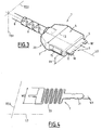
- Figures 3 and 4 illustrate another feature which can also provide for a lower thickness T1 of a connector 1.
- Figures 3 and 4 show a connector 1 having the same general design as the connector 1 of Figures 1 and 2, but for the absence of an exposed shield 6, such as the exposed shield 6 of Figures 1 and 2.
- such a shield 6 may be absent in the connector 1 of figures 3 and 4.
- FIGS 3 and 4 only two terminals 7 have been shown, for clarity. However, the connector 1 may of course comprise more than two terminals 7.
- each terminal 7 of the connector 1 extends along the longitudinal direction LD and comprises a contacting end portion 31 and a spring portion 33.
- the portion 31 protrudes out of the insulating body 5 and the portion 33 is embedded in the insulating body 5.
- the spring portion 33 is carried by the insulating body 5 and provides for an electrical connection of the contacting end portion 31 to the wires of the cable 8.
- the conventional purpose of the contacting end portions 31 is to be placed in contact with contact elements of the connector 2 to establish an electrical connection when connectors 1 and 2 are in abutment.
- the springs portions 33 allows the contacting portions 31 to move transversally with respect to the insulating body 5, thereby reducing potential damages of the contact elements of connector 2 during connection to the connector 1.
- the spring portions 33 have a serpentine shape. This serpentine extends in a plane defined by the longitudinal direction LD and the second transversal direction TD2.
- the terminals 7 have a greater width W2 along the second transversal direction TD2 and a smaller width W1 along the first transversal direction TD1.
- the thickness T1 of the connector 1 along the first transversal direction TD1 can be diminished.
- the terminals 7 may be inclined, with respect to the plane defined by the longitudinal direction LD and the transversal direction TD2, by an angle comprised between 0 and 45°.
- this orientation of the terminals 7 may be used alone, as shown on Figures 3 and 4, or in combination with the feature illustrated by Figures 1 and 2 and relating to the opening(s) in the outer housing receiving the shield 6.
Landscapes
- Details Of Connecting Devices For Male And Female Coupling (AREA)
- Coupling Device And Connection With Printed Circuit (AREA)
- Connector Housings Or Holding Contact Members (AREA)
- Massaging Devices (AREA)
- Paper (AREA)
Applications Claiming Priority (1)
| Application Number | Priority Date | Filing Date | Title |
|---|---|---|---|
| EP04290401A EP1575133B1 (de) | 2004-02-13 | 2004-02-13 | Verbinder in dünner Bauweise |
Related Parent Applications (1)
| Application Number | Title | Priority Date | Filing Date |
|---|---|---|---|
| EP04290401A Division EP1575133B1 (de) | 2004-02-13 | 2004-02-13 | Verbinder in dünner Bauweise |
Publications (2)
| Publication Number | Publication Date |
|---|---|
| EP1788668A2 true EP1788668A2 (de) | 2007-05-23 |
| EP1788668A3 EP1788668A3 (de) | 2008-03-26 |
Family
ID=34814413
Family Applications (2)
| Application Number | Title | Priority Date | Filing Date |
|---|---|---|---|
| EP07004923A Withdrawn EP1788668A3 (de) | 2004-02-13 | 2004-02-13 | Verbinder in dünner Bauweise |
| EP04290401A Expired - Lifetime EP1575133B1 (de) | 2004-02-13 | 2004-02-13 | Verbinder in dünner Bauweise |
Family Applications After (1)
| Application Number | Title | Priority Date | Filing Date |
|---|---|---|---|
| EP04290401A Expired - Lifetime EP1575133B1 (de) | 2004-02-13 | 2004-02-13 | Verbinder in dünner Bauweise |
Country Status (7)
| Country | Link |
|---|---|
| EP (2) | EP1788668A3 (de) |
| KR (1) | KR20060108778A (de) |
| CN (1) | CN1918754A (de) |
| AT (1) | ATE357070T1 (de) |
| DE (1) | DE602004005302T2 (de) |
| TW (1) | TW200534541A (de) |
| WO (1) | WO2005081368A1 (de) |
Families Citing this family (1)
| Publication number | Priority date | Publication date | Assignee | Title |
|---|---|---|---|---|
| KR20160046366A (ko) | 2014-10-20 | 2016-04-29 | 정인환 | 열기 및 스팀 혼합 가열식 구이용 불판 |
Family Cites Families (5)
| Publication number | Priority date | Publication date | Assignee | Title |
|---|---|---|---|---|
| DE3727241A1 (de) * | 1986-08-19 | 1988-03-03 | Feinmetall Gmbh | Kontaktiervorrichtung |
| US5055070A (en) * | 1990-08-29 | 1991-10-08 | Labinal Components And Systems, Inc. | Overmolded shielded connector |
| JP3520468B2 (ja) * | 2000-06-21 | 2004-04-19 | 日本航空電子工業株式会社 | コネクタ |
| NL1017001C2 (nl) * | 2000-12-28 | 2002-07-01 | Fci S Hertogenbosch B V | Connector en kabel die deze omvat. |
| JP4584504B2 (ja) * | 2001-08-20 | 2010-11-24 | 富士通コンポーネント株式会社 | 平衡伝送用コネクタ |
-
2004
- 2004-02-13 DE DE602004005302T patent/DE602004005302T2/de not_active Expired - Fee Related
- 2004-02-13 EP EP07004923A patent/EP1788668A3/de not_active Withdrawn
- 2004-02-13 EP EP04290401A patent/EP1575133B1/de not_active Expired - Lifetime
- 2004-02-13 AT AT04290401T patent/ATE357070T1/de not_active IP Right Cessation
-
2005
- 2005-02-11 KR KR1020067018631A patent/KR20060108778A/ko not_active Withdrawn
- 2005-02-11 CN CNA2005800042535A patent/CN1918754A/zh active Pending
- 2005-02-11 WO PCT/EP2005/001463 patent/WO2005081368A1/en not_active Ceased
- 2005-02-14 TW TW094104228A patent/TW200534541A/zh unknown
Also Published As
| Publication number | Publication date |
|---|---|
| EP1788668A3 (de) | 2008-03-26 |
| DE602004005302D1 (de) | 2007-04-26 |
| CN1918754A (zh) | 2007-02-21 |
| EP1575133B1 (de) | 2007-03-14 |
| DE602004005302T2 (de) | 2008-02-14 |
| EP1575133A1 (de) | 2005-09-14 |
| TW200534541A (en) | 2005-10-16 |
| ATE357070T1 (de) | 2007-04-15 |
| WO2005081368A1 (en) | 2005-09-01 |
| KR20060108778A (ko) | 2006-10-18 |
Similar Documents
| Publication | Publication Date | Title |
|---|---|---|
| CN109804511B (zh) | 连接器结构 | |
| EP2019456B1 (de) | Elektrischer Steckverbinder | |
| EP2019453B1 (de) | Schaltungsplattenstecker, Steckverbinder und elektronische Vorrichtung mit einem solchen Schaltungsplattenstecker | |
| JP4368897B2 (ja) | コネクタ | |
| CN110061375B (zh) | 连接器、对接连接器以及连接器组件 | |
| EP1914841B1 (de) | Elektrischer Steckverbinder | |
| US20070298658A1 (en) | Electrical docking connector | |
| CN109792124B (zh) | 连接器结构 | |
| US9350119B2 (en) | Wrong insertion preventive structure of connector | |
| US6814605B2 (en) | Connector having a shielding shell provided with a locking portion | |
| JPH11126636A (ja) | 圧接コネクタのカバー固定構造 | |
| JP7023499B2 (ja) | 電気コネクタ | |
| CN110277678A (zh) | 连接器 | |
| JP5315912B2 (ja) | 多連装電気コネクタ | |
| US7438595B2 (en) | Small-sized electrical connector easily improved in EMI characteristics | |
| KR101157672B1 (ko) | 커넥터 | |
| US10862236B2 (en) | Connector | |
| EP1686663B1 (de) | Elektrischer Verbinder mit einem Teill zur Aufnahme von Biegekräften während der Kupplung mit Gegenverbindern | |
| US7556530B2 (en) | Connector in which defective electrical connection between a plurality of shell components is suppressed | |
| JP2019185875A (ja) | 端子押し付け構造を有するコネクタ装置 | |
| EP1575133B1 (de) | Verbinder in dünner Bauweise | |
| CN109728462B (zh) | 连接器 | |
| JP2020187896A (ja) | コネクタ | |
| CN110391530B (zh) | 阴端子 | |
| US11381009B2 (en) | Contact and connector |
Legal Events
| Date | Code | Title | Description |
|---|---|---|---|
| PUAI | Public reference made under article 153(3) epc to a published international application that has entered the european phase |
Free format text: ORIGINAL CODE: 0009012 |
|
| AC | Divisional application: reference to earlier application |
Ref document number: 1575133 Country of ref document: EP Kind code of ref document: P |
|
| AK | Designated contracting states |
Kind code of ref document: A2 Designated state(s): AT BE BG CH CY CZ DE DK EE ES FI FR GB GR HU IE IT LI LU MC NL PT RO SE SI SK TR |
|
| PUAL | Search report despatched |
Free format text: ORIGINAL CODE: 0009013 |
|
| AK | Designated contracting states |
Kind code of ref document: A3 Designated state(s): AT BE BG CH CY CZ DE DK EE ES FI FR GB GR HU IE IT LI LU MC NL PT RO SE SI SK TR |
|
| RIC1 | Information provided on ipc code assigned before grant |
Ipc: H01R 13/24 20060101ALI20080219BHEP Ipc: H01R 13/658 20060101AFI20070403BHEP |
|
| 17P | Request for examination filed |
Effective date: 20080926 |
|
| AKX | Designation fees paid |
Designated state(s): AT BE BG CH CY CZ DE DK EE ES FI FR GB GR HU IE IT LI LU MC NL PT RO SE SI SK TR |
|
| 17Q | First examination report despatched |
Effective date: 20081106 |
|
| STAA | Information on the status of an ep patent application or granted ep patent |
Free format text: STATUS: THE APPLICATION IS DEEMED TO BE WITHDRAWN |
|
| 18D | Application deemed to be withdrawn |
Effective date: 20090317 |