EP1789320B1 - Strahltriebwerkpylon für ein flugzeug - Google Patents
Strahltriebwerkpylon für ein flugzeug Download PDFInfo
- Publication number
- EP1789320B1 EP1789320B1 EP05857325A EP05857325A EP1789320B1 EP 1789320 B1 EP1789320 B1 EP 1789320B1 EP 05857325 A EP05857325 A EP 05857325A EP 05857325 A EP05857325 A EP 05857325A EP 1789320 B1 EP1789320 B1 EP 1789320B1
- Authority
- EP
- European Patent Office
- Prior art keywords
- arcs
- pylon
- engine
- aircraft
- set forth
- Prior art date
- Legal status (The legal status is an assumption and is not a legal conclusion. Google has not performed a legal analysis and makes no representation as to the accuracy of the status listed.)
- Expired - Lifetime
Links
Images




Classifications
-
- B—PERFORMING OPERATIONS; TRANSPORTING
- B64—AIRCRAFT; AVIATION; COSMONAUTICS
- B64D—EQUIPMENT FOR FITTING IN OR TO AIRCRAFT; FLIGHT SUITS; PARACHUTES; ARRANGEMENT OR MOUNTING OF POWER PLANTS OR PROPULSION TRANSMISSIONS IN AIRCRAFT
- B64D27/00—Arrangement or mounting of power plants in aircraft; Aircraft characterised by the type or position of power plants
- B64D27/40—Arrangements for mounting power plants in aircraft
- B64D27/402—Arrangements for mounting power plants in aircraft comprising box like supporting frames, e.g. pylons or arrangements for embracing the power plant
-
- B—PERFORMING OPERATIONS; TRANSPORTING
- B64—AIRCRAFT; AVIATION; COSMONAUTICS
- B64D—EQUIPMENT FOR FITTING IN OR TO AIRCRAFT; FLIGHT SUITS; PARACHUTES; ARRANGEMENT OR MOUNTING OF POWER PLANTS OR PROPULSION TRANSMISSIONS IN AIRCRAFT
- B64D27/00—Arrangement or mounting of power plants in aircraft; Aircraft characterised by the type or position of power plants
- B64D27/40—Arrangements for mounting power plants in aircraft
- B64D27/404—Suspension arrangements specially adapted for supporting vertical loads
Definitions
- the present invention relates generally to a turbojet engine mount for an aircraft.
- This type of attachment pole also called “EMS” (of the English “Engine Mounting Structure”), allows to suspend the turbojet below the wing of the aircraft, or to mount the turbojet engine above of this same wing.
- Such an attachment mast is in fact provided to form the connecting interface between a turbojet engine and a wing of the aircraft. It makes it possible to transmit to the structure of this aircraft the forces generated by its associated turbojet, and also authorizes the routing of fuel, electrical, hydraulic and air systems between the engine and the aircraft.
- the mast has a rigid structure, often of the "box" type, that is to say formed by the assembly of upper and lower spars and side panels connected together by the intermediate transverse ribs.
- the mast is provided with a mounting system interposed between the turbojet engine and the rigid structure of the mast, this system generally comprising at least two engine fasteners, generally at least one front attachment and at least one rear attachment.
- the mounting system comprises a device for taking up the thrust forces generated by the turbojet engine.
- this device takes for example the form of two lateral connecting rods connected on the one hand to a rear part of the turbojet fan casing, and on the other hand to a rear attachment fixed to the central casing of the latter .
- the attachment mast also includes a second mounting system interposed between the rigid structure of the mast and the wing of the aircraft, the second system usually consisting of two or three fasteners.
- the mast is provided with a secondary structure ensuring the segregation and maintenance of the systems while supporting aerodynamic fairings.
- a conventional attachment mast of the prior art roughly takes the form of a parallelepiped box, having large dimensions in order to be able to take all the forces generated by the associated turbojet engine.
- this mast then inevitably causes significant disturbances of the secondary flow escaping from the annular fan duct, which which translates directly into losses in terms of drag, turbojet performance, and fuel consumption.
- these disturbances are naturally accentuated by the presence of the thrust recovery rods arranged at the outlet of the annular fan duct.
- the object of the invention is therefore to propose an aircraft turbojet engine mount which at least partially overcomes the aforementioned drawbacks relating to the embodiments of the prior art, and also to present an aircraft having at least one such aircraft mast.
- the subject of the invention is an aircraft turbojet engine mount, having a rigid structure comprising a plurality of arches arranged so as to jointly delimit a portion of a substantially cylindrical dummy surface of circular section. the plurality of arches having at least one annular portion shaped bar substantially centered on a longitudinal axis of the imaginary surface.
- the rigid structure of the attachment mast comprises a central box, also called central torsion box, which extends parallel to the longitudinal axis of the dummy surface, and which is integral with each ring shaped annular portion.
- the plurality of arches also comprises two lateral arches for taking up the thrust forces respectively disposed on either side of the central box, each of the two lateral arches being secured on the one hand to each ring in the form of an annular portion. , and secondly to the central box.
- each of the arches of the plurality of arches thus has a curvature allowing it to extend around this substantially cylindrical imaginary surface of circular section. They therefore together form an assembly of the rigid structure which is advantageously capable of being only very restrictive in terms of disturbance of the secondary flow escaping from the annular fan duct of the turbojet engine associated with it, compared with conventional solutions of the invention.
- prior art in which the attachment mast took the form of a large parallelepipedal central box disposed very close to the central casing of the turbojet engine.
- a diameter of the dummy surface is substantially identical to a diameter of an outer cylindrical surface of the fan casing of the associated turbojet, implying that the rigid assembly formed by the plurality of hoops is located then substantially in the extension of this outer surface of the housing of blower, and more generally in the extension of a peripheral annular portion of this housing.
- the plurality of hoops is similar to a portion of a substantially cylindrical envelope of circular section and of diameter close to that of the fan casing, the disturbances of the secondary flow may be caused by this plurality of hoops are extremely weak or almost non-existent.
- the plurality of arches is generally comparable to a portion of a substantially cylindrical envelope of circular section, it preferably takes the form of a portion of a substantially cylindrical section envelope semicircular, the concept of "portion" being naturally present due to the empty spaces between the different arches.
- this preferred form is entirely adapted to ensure easy mounting of the turbojet engine on the rigid structure of the suspension pylon.
- the plurality of arches comprises at least one annular portion shaped bar substantially centered on a longitudinal axis of the dummy surface, this longitudinal axis being parallel to the longitudinal direction of the mast, and preferably intended to be confused with the longitudinal axis of the turbojet engine.
- it is on such an arch in the form of annular portion that can be fixed all of the aforementioned engine fasteners.
- the mechanical strength provided by the arches allows the central box to have smaller dimensions than those previously used, mainly with regard to its thickness. This implies that this central box is also able to cause only very small disturbances of the secondary flow escaping from the annular fan duct. Furthermore, it should also be observed that the small thickness of the central box is authorized because it is no longer intended to interpose a rear engine attachment between the same box and the central casing of the turbojet, and that it is therefore no longer necessary to approach the box as close as possible to this housing, as was the case previously.
- the plurality of hoops to further comprise two secondary lateral hoops for taking up thrust forces. disposed respectively on either side of the central box, each of these two secondary side arches being secured on the one hand to at least one ring-shaped annular portion, and the other to the central box.
- the plurality of arches may also comprise two arches for holding the lateral arches for taking up the thrust forces, these two holding arches being disposed respectively on either side of the central box and each secured on the one hand to one of two side arches, and secondly to the central box.
- the holding arches are arranged to work in tension, and prevent the deflection of the side arches of recovery of thrust forces.
- the attachment pylon comprises a plurality of engine attachments, each of them being fixed to the plurality of hoop.
- these engine fasteners of the attachment mast are all intended to be attached to the fan casing of the turbojet cooperating with the same mast.
- this particular arrangement of the engine fasteners on the rigid structure of the mast is capable of inducing a considerable reduction in the bending encountered at the central casing, whether this bending is due to the thrust forces generated by the turbojet engine, or due to the bursts likely to be encountered during the various flight phases of the engine. aircraft.
- the distance practiced may for example be approximately equal to the diameter of the dummy surface, which is much greater than a width of the central box.
- This large spacing has the advantage of being able to considerably simplify the design of these engine fasteners, due to the fact that the efforts they must resume, associated with a given moment along a given axis, are naturally weakened compared to those encountered in the solutions. conventional of the prior art in which the engine fasteners intended to be fixed on the central casing could not be so far apart.
- the engine fasteners and the rigid structure of the suspension pylon may advantageously be located at distance from the hot part of the associated turbojet engine, which implies a significant decrease in the thermal effects likely to apply to these elements.
- the plurality of motor attachments consists of a first motor attachment and a second motor attachment located symmetrically with respect to a plane defined by the longitudinal axis of the dummy surface and a vertical direction of the mast, as well as a third engine attachment traversed by the same plane.
- the first, second and third motor fasteners are fixed on the same annular portion of the annular portion of the plurality of arches, which allows them to occupy positions in which they are advantageously very far apart from each other. Being located on the same ring shaped annular portion, the engine fasteners can easily be attached to the peripheral annular portion of the fan casing.
- the first and second motor fasteners are traversed by a plane defined by the longitudinal axis of the fictitious surface and a transverse direction of the attachment pylon.
- first and second engine attachments are each designed to take up forces exerted in a longitudinal direction of the mast and in the vertical direction thereof, and the third engine attachment is designed to resume of the forces exerted along the same longitudinal direction of the mast, and in a transverse direction thereof.
- the invention also relates to an aircraft comprising at least one attachment pole such as that which has just been presented.
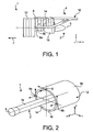
- the engine unit 1 is composed of a turbojet engine 2 and the engine mount 4, the latter being provided in particular with a plurality of engine attachments 6a, 6b, 8, and a rigid structure 10 carrying these same fasteners (the fastener 6b being masked by the fastener 6a on this figure 1 ).
- the assembly 1 is intended to be surrounded by a nacelle (not shown), and that the attachment pylon 4 comprises another series of fasteners (not shown) to ensure the suspension of this assembly 1 under the wing of the aircraft.
- X is the longitudinal direction of the mast 4 which is also comparable to the longitudinal direction of the turbojet engine 2, this direction X being parallel to a longitudinal axis 5 of the turbojet engine 2.
- Y is the direction transversely oriented with respect to the mast 4 and also comparable to the transverse direction of the turbojet 2
- Z is the vertical or height direction, these three directions X, Y and Z being orthogonal to one another.
- front and rear are to be considered in relation to a direction of advancement of the aircraft encountered following the thrust exerted by the turbojet engine 2, this direction being represented schematically by the arrow 7.
- the turbojet engine 2 has at the front of a large fan casing 12 delimiting an annular fan duct 14, and comprises a rearward central casing 16 of smaller size, enclosing the heart of this turbojet engine.
- the housings 12 and 16 are of course integral with each other.
- the engine fasteners 6a, 6b, 8 of the mast 4 are all fixed on the fan casing 12 mentioned above.
- first fastener 6a and the second fastener 6b are arranged symmetrically with respect to a first plane (not shown) defined by the longitudinal axis 5 and the direction Z.
- the fasteners 6a, 6b are both attached to a peripheral annular portion 18 of the fan casing 12, and preferably on the back of this portion 18, as shown schematically.
- first and second engine fasteners 6a, 6b are diametrically opposed on the peripheral annular portion 18 having a cylindrical outer surface 38 of the fan casing 12, so that these fasteners 6a, 6b are each traversed by a second plane defined by the longitudinal axis 5 and the Y direction of the mast 4.
- each of the first and second engine fasteners 6a, 6b is designed so as to be able to take up forces generated by the turbojet engine 2 in the direction X and in the direction Z, but not those acting in the direction Y.
- the two fasteners 6a, 6b strongly spaced apart from each other jointly ensure the recovery of the moment exerted in the direction X, and that of the moment acting in the direction Z.
- the third motor attachment 8 shown schematically is also attached to the peripheral annular portion 18 of the fan casing 12, also preferably on the rear of this portion 18.
- the fasteners 6a, 6b, 8 are fixed on the peripheral annular portion 18 of the casing 12 via structural parts (not shown) of the engine, which are actually preferably arranged on the rear
- structural parts not shown
- the third fastener 8 it is located on the highest part of the fan casing 12, and thus on the highest part of the peripheral annular part 18, and is therefore traversed fictitiously by the first plane. indicated above.
- the third engine attachment 8 is designed so as to be able to take up forces generated by the turbojet engine 2 in the direction X and in the direction Y, but not those acting in the direction Z.
- this third fastener 8 together with the two fasteners 6a, 6b ensures the recovery of the moment exerted in the direction Y.
- the main advantage associated with the configuration just described lies in the fact that the total freedom of the central casing 16 vis-à-vis the engine fasteners 6a, 6b, 8 causes a considerable decrease of the bending of this casing during the various flight situations of the aircraft, and thus causes a significant decrease in the friction wear of the aircraft. compressor and turbine blades against this central casing 16.
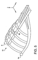
- this rigid structure 10 is designed to have a symmetry with respect to the first plane indicated above, that is to say with respect to the vertical plane defined by the longitudinal axis 5 of the turbojet 2, and the direction Z.
- This rigid structure 10 comprises a central torsion box 20, which extends from one end to the other of the structure 10 in the X direction, parallel to this same direction.
- this box 20 may be formed by the assembly of two side rails 22 extending in the X direction in parallel XZ planes, and connected to each other by means of transverse ribs 24 which are themselves oriented in parallel YZ planes.
- a plurality of arches 30 is provided to complete the rigid structure 10 whose central box 20 is located at an upper portion of the same structure 10, each of the arches being secured to the central torsion box 20 and protruding from on both sides of it in direction Y.
- this plurality of arches 30 delimits a portion of a substantially cylindrical fictitious surface 32 of circular section, and of longitudinal axis 34 parallel to the central box 20, as shown in FIG. figure 3 .
- the arches 26, 28 constituting the plurality of arches 30 each have a curvature adapted to be positioned around and in contact with the imaginary surface 32, over their entire length.
- the plurality of arches 30 forms a portion of a casing / cage substantially cylindrical of circular section, capable of being positioned around and at a distance from the central casing 16 of the turbojet engine 2.
- the rigid structure 10 also has a symmetry with respect to the vertical plane defined by the longitudinal axis 34 and the Z direction of the mast 4.
- the arches 26 are spaced apart from each other in the X direction, and arranged in parallel YZ planes. In addition, they are secured to the central box 20 which passes through each of them in the middle. More specifically, each annular portion shaped bar 26 passes through the two side rails 22, and is fixed rigidly to these two last, for example by welding or mechanical assembly.
- hoops 26 may each be made in one piece, or for example by means of two identical parts rigidly attached to one another.
- the arches 26 are four in number, and have a length that decreases as they approach the rear of the structure 10.
- the arch 26 located on the further to the front of the structure 10 and integral with a front end of the central box 20 has the shape of a half-ring whose two ends are therefore arranged substantially at the XY plane passing through the longitudinal axis 34, this plane being identical to the aforementioned second plane, again because of the identity between the axes 5 and 34.
- the second hoop 26 has meanwhile a length slightly less than that of a half-ring, and so on until the last arch 26 located for example at a central portion of the box 20, considered in the direction X.
- the front part of the central box 20 traversed by the annular portion shaped arches 26 does not necessarily require the integration of transverse ribs 24, since the two side rails 22 are connected to each other by the upper part of these arches. 26.
- the plurality of hoops 30 also comprises two lateral hoops of recovery efforts 28 (only one being visible on the figure 3 , because of the perspective representation). These arches 28 are effectively arranged in such a way as to be able to take up the thrust forces generated by the turbojet engine 2 during the various flight phases of the aircraft, with the obvious aim of limiting the longitudinal bending of this turbojet engine 2, and more specifically that of its fan case 12.
- a hoop 28 is disposed on each side of the central box 20, and has a front portion rigidly connected to the hoops 26, and a rear portion rigidly connected to the central box 20. More specifically, each of the two hoops 28 has a front end secured to one of the two ends of the bow 26 the front, and extends rearwardly and upwardly being rigidly connected to one of the two ends of each of the other arches 26. Then , its rear end is assembled on the side spar 22 located on the same side as the bow 28 concerned, at a rear portion of the box 20. It should be observed that a reinforcement 36 could possibly be added to reinforce the mechanical connection established between the rear end of the arch 28 and the associated lateral spar 22, this connection being for example obtained by welding or by mechanical assembly.
- the figure 4a represents a sectional view taken along a transverse plane P1 situated between the two most forward arches 26, and the figure 4b represents a sectional view taken along a plane P2 also transversely located at the rear of the arch 26 the most rear, but in front of the junction between the arch 28 and the central box 20.
- the plurality of hoops 30 delimits a portion of the substantially cylindrical dummy surface 32 of circular section, and that this plurality of hoops 30 constitutes a portion of a substantially cylindrical envelope / cage of semicircular section centered on the longitudinal axis 34, as will also be described with reference to the figure 4c .
- the diameter of the cylindrical dummy surface 32 is preferably substantially identical to the diameter of the cylindrical outer surface 38 of the annular portion 18 12.
- the side rails 22 protrude only a very small distance within the space 35 delimited by the dummy surface 32, so that they also do not significantly disturb the flow of the secondary air flow .
- the longitudinal members 22 have a height in the Z direction which is extremely small compared to the diameter of the imaginary 32 and outer 38 surfaces. Moreover, this is only a lower part of these rails 22 which penetrates inside the space 35, the other part being above the plurality of arches 30.
- the figure 4c shows that it constitutes a part only of a substantially cylindrical casing / cage 40 of semicircular section, centered on the longitudinal axis 34 and surrounding the upper half of the imaginary surface 32.
- the shaded parts 42 correspond to the parts missing from the plurality of hoops 30 to form the complete half-cylinder 40.
- this representation also makes it possible to understand that the plurality of hoops 30 substantially forms an extension. towards the rear of the peripheral annular portion 18 of the fan casing 12.
- the rigid structure 10 of the attachment pylon 4 is entirely adapted to support the engine fasteners 6a, 6b, 8, since these can be easily fixed on the bow 26 the furthest forward.
- the first and second fasteners 6a, 6b are respectively fixed to the two ends of the bow 26 the more forward in the form of half-ring, while the third fastener 8 is secured to the upper part of the same arch 26, located between the two lateral spars 22 of the central box 20.
- the third fastener 8 is then also located between these two horizontal spars of the central box 20.
- the two engine attachments 6a, 6b are arranged symmetrically with respect to the plane defined by the longitudinal axis 34 and the Z direction of the mast 4, just as the third engine attachment 8 is crossed by the same plane identical to the foreground mentioned above.
- all the constituent elements of the rigid structure 10 which has just been described is made using metal materials, such as steel, aluminum, titanium, or at least one of the following: using composite materials, preferably carbon.
- the arches of the plurality of arches 30 may each take the form of a curved sheet metal strip.
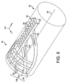
- the figures 6 and 7 respectively represent first and second alternative embodiments of the rigid structure 10 described above with reference to the figure 3 .
- the elements bearing the same reference numerals correspond to identical or similar elements.
- the plurality of hoops 130 has been modified with respect to the plurality of hoops 30 described above, it is always made so as to delimit a portion of the substantially cylindrical dummy surface 32 of circular section, and preferably constituting a portion of a substantially cylindrical casing / cage of semicircular section, centered on the longitudinal axis 34.
- a hoop 142 is disposed on each side of the central box 20, and has a front end rigidly connected to one of the two ends of the bow 26 the farthest, the mechanical connection being made for example just above the fixing between the same front bow 26 and the bow 28. Furthermore, the secondary side bar of recovery of the thrust forces 142 extends rearwardly and upwardly until its rear end comes s' assemble on the lateral spar 22 located on the same side as this arch 142, at a central portion of the box 20.
- a reinforcement 144 could possibly be added to reinforce the mechanical connection established between the rear end of the hoop 142 and the lateral spar 22 associated, this connection being for example obtained by welding or mechanical assembly.
- the secondary side bar of recovery of the thrust forces 142 can cross the other two annular portion shaped arches 26 without necessarily being secured to them.
- the plurality of hoops 230 has been modified with respect to the plurality of hoops 130 which has just been described, but that it is always made so as to delimit part of the substantially cylindrical fictitious surface 32 of circular section, and preferably constituting part of a substantially cylindrical casing / cage of semicircular section, centered on the longitudinal axis 34.
- a holding bar 246 is disposed on each side of the central box 20, and has a front end rigidly connected to a front portion of the box 20.
- the holding bar 246 extends rearwardly and downwardly. until its rear end comes to assemble on the bar of recovery of the thrust forces 28 located on the same side as this arch 246, at a substantially central portion of this arch 28.
- the support arches 246 working in tension allow the rollbars to take up the thrust forces 28 not to bend during the various phases of flight of the aircraft, and therefore avoid a gap significant occurs between the two arches 28 and 142 on the same side of the rigid structure 10.
- the arches 142 and 246 form a substantially X.
- the holding bar 246 can cross the secondary side bar of recovery efforts of thrust 142 without necessarily being secured to it.
- the central box 20 of the first and second alternative embodiments of the mast 4 may also undergo some minor modifications, for example with regard to the arrangement and the number of transverse ribs 24.
- FIGS. 8a to 8c represent views illustrating different successive stages of the assembly operation of the turbojet engine 2 on the rigid structure 10 which has just been described, that is to say the one in the form of the second alternative.
- the turbojet 2 being in a position where its front is slightly inclined downwards undergoes an upward movement, for example using a conventional forklift (not shown), in the direction of the rigid structure 10 maintained fixedly.
- the fasteners 6a, 6b are placed between the ends of the front bow 26 and the peripheral annular portion 18 of the fan casing 12.
- turbojet engine 2 is pivoted around the first and second fasteners 6a, 6b so that its fan casing 12 can rise, as shown schematically by the arrow of the figure 8b .
- the figure 8c for its part shows that the pivoting of the turbojet engine 2 is stopped as soon as the peripheral annular portion 18 is sufficiently close to the front rollbar 26 so that the third engine fastener 8 can be put in place.
Landscapes
- Engineering & Computer Science (AREA)
- Aviation & Aerospace Engineering (AREA)
- Structures Of Non-Positive Displacement Pumps (AREA)
- Turbine Rotor Nozzle Sealing (AREA)
- Refuge Islands, Traffic Blockers, Or Guard Fence (AREA)
- Rod-Shaped Construction Members (AREA)
- Tires In General (AREA)
- Vibration Dampers (AREA)
Claims (13)
- Aufhängungsmast (4) eines Strahltriebwerks (2) für ein Luftfahrzeug, wobei der Mast über eine starre Struktur (10) verfügt und die starre Struktur (10) mehrere Bogenstücke (30,130,230) aufweist, die so angeordnet sind, dass sie gemeinsam einen Abschnitt einer fiktiven Oberfläche (32) begrenzen, die im wesentlichen zylindrisch mit kreisförmigem Querschnitt ist,
wobei die mehreren Bogenstücke (30,130,230) mindestens ein Bogenstück in Form eines Ringabschnitts (26) aufweisen, der im wesentlichen auf eine Longitudinalachse (34) der fiktiven Oberfläche (32) zentriert ist,
wobei die starre Struktur (10) des Aufhängungsmasts (4) einen zentralen Kasten (20) aufweist, der sich parallel zu der Longitudinalachse (34) der fiktiven Oberfläche (32) erstreckt und mit jedem Bogenstück in Form eines Ringabschnitts (22) fest verbunden bzw. einstückig ist,
dadurch gekennzeichnet, dass die mehreren Bogenstücke (30,130,230) außerdem zwei laterale Bogenstücke zur Aufnahme von Schubkräften (28) umfasst, die jeweils auf beiden Seiten des zentralen Kastens (20) angeordnet sind, wobei jedes der zwei lateralen Bogenstücke (28) einerseits mit jedem Bogenstück in Form eines Ringabschnitts (26) und andererseits mit dem zentralen Kasten (20) fest verbunden bzw. einstückig ist. - Aufhängungsmast (4) für ein Luftfahrzeug nach Anspruch 1, dadurch gekennzeichnet, dass die mehreren Bogenstücke (130,230) außerdem zwei sekundäre laterale Bogenstücke zur Aufnahme von Schubkräften (142) umfasst, die jeweils auf beiden Seiten des zentralen Kastens (20) angeordnet sind,
wobei die beiden sekundären lateralen Bogenstücke (142) einerseits mit mindestens einem Bogenstück in Form eines Ringabschnitts (26) und andererseits mit dem zentralen Kasten (20) einstückig bzw. fest verbunden sind. - Aufhängungsmast (4) für ein Luftfahrzeug nach Anspruch 1 oder Anspruch 3, dadurch gekennzeichnet, dass die mehreren Bogenstücke (230) auch zwei Bogenstücke (246) zum Halten der lateralen Bogenstücke zur Aufnahme von Schubkräften (28) umfassen, wobei die beiden Bogenstücke (246) zum Halten jeweils auf beiden Seiten des zentralen Kastens (20) angeordnet sind und jeweils einerseits mit den beiden lateralen Bogenstücken (26) und andererseits mit dem zentralen Kasten (20) einstückig bzw. fest verbunden sind.
- Aufhängungsmast (4) für ein Luftfahrzeug nach einem der Ansprüche 1 bis 3, dadurch gekennzeichnet, dass jedes der beiden lateralen Bogenstücke zur Aufnahme von Schubkräften (28) mit einem Ende jedes Bogens in Form eines Ringabschnitts (26) einstückig bzw. fest verbunden ist.
- Aufhängungsmast (4) für ein Luftfahrzeug nach einem der Ansprüche 1 bis 4, dadurch gekennzeichnet, dass mindestens ein Bogenstück in Form eines Ringabschnitts (26) ein Halbring ist.
- Aufhängungsmast (4) für ein Luftfahrzeug nach einem der vorangehenden Ansprüche, dadurch gekennzeichnet, dass die mehreren Bogenstücke (30,130,230) die Form eines Abschnitts einer im wesentlichen zylindrischen Umhüllung (40) von halbkreisförmigem Querschnitt aufweisen.
- Aufhängungsmast (4) für ein Luftfahrzeug nach einem der vorangehenden Ansprüche, dadurch gekennzeichnet, dass er mehrere Triebwerk-Befestigungselemente (6a,6b,8) aufweist, wobei jedes hiervon an den mehreren Bogenstücken (30,130,230) befestigt ist.
- Aufhängungsmast (4) für ein Luftfahrzeug nach Anspruch 7, dadurch gekennzeichnet, dass die mehreren Triebwerk-Befestigungselemente (6a,6b,8) aus einem ersten Triebwerk-Befestigungselement (6a) und einem zweiten Triebwerk-Befestigungselement (6b) gebildet sind, die symmetrisch in bezug auf eine Ebene angeordnet sind, welche durch die Longitudinalachse (34) der fiktiven Oberfläche (32) und eine Vertikalrichtung (Z) dieses Masts festgelegt ist, sowie aus einem dritten Triebwerk-Befestigungselement (8), das von dieser Ebene durchsetzt wird.
- Aufhängungsmast (4) für ein Luftfahrzeug nach Anspruch 8, dadurch gekennzeichnet, dass die ersten, zweiten und dritten Triebwerk-Befestigungselemente (6a,6b,8) auf ein und demselben Bogenstück in Form eines Ringabschnitts (26) befestigt sind, welcher zu den mehreren Bogenstücken (30,130,230) gehört.
- Aufhängungsmast (4) für ein Luftfahrzeug nach Anspruch 8 oder Anspruch 9, dadurch gekennzeichnet, dass die ersten und zweiten Triebwerk-Befestigungselemente (6a,6b) von einer Ebene durchsetzt sind, die durch die Longitudinalachse (34) der fiktiven Oberfläche (32) und eine Transversalrichtung (Y) dieses Masts festgelegt ist.
- Aufhängungsmast (4) für ein Luftfahrzeug nach einem der Ansprüche 8 bis 10, dadurch gekennzeichnet, dass die ersten und zweiten Triebwerk-Befestigungselemente (6a,6b) jeweils so ausgelegt sind, dass sie Kräfte aufnehmen, die in einer Longitudinalrichtung (X) des Masts (4) und in einer Vertikalrichtung (Z) dieses Masts ausgeübt werden.
- Aufhängungsmast (4) für ein Luftfahrzeug nach einem der Ansprüche 8 bis 11, dadurch gekennzeichnet, dass das dritte Triebwerk-Befestigungselement (8) so ausgelegt ist, dass es Kräfte aufnimmt, die in der Longitudinalrichtung (X) des Masts (4) und in der Transversalrichtung (Y) dieses Masts ausgeübt werden.
- Luftfahrzeug, dadurch gekennzeichnet, dass es mindestens einen Aufhängungsmast (4) gemäß einem der vorangehenden Ansprüche aufweist.
Applications Claiming Priority (2)
| Application Number | Priority Date | Filing Date | Title |
|---|---|---|---|
| FR0451791A FR2873988B1 (fr) | 2004-08-05 | 2004-08-05 | Mat d'accrochage de turboreacteur pour aeronef |
| PCT/FR2005/050645 WO2006090032A1 (fr) | 2004-08-05 | 2005-08-03 | Mat d'accrochage de turboreacteur pour aeronef |
Publications (2)
| Publication Number | Publication Date |
|---|---|
| EP1789320A1 EP1789320A1 (de) | 2007-05-30 |
| EP1789320B1 true EP1789320B1 (de) | 2008-06-11 |
Family
ID=34948383
Family Applications (1)
| Application Number | Title | Priority Date | Filing Date |
|---|---|---|---|
| EP05857325A Expired - Lifetime EP1789320B1 (de) | 2004-08-05 | 2005-08-03 | Strahltriebwerkpylon für ein flugzeug |
Country Status (11)
| Country | Link |
|---|---|
| US (1) | US7784733B2 (de) |
| EP (1) | EP1789320B1 (de) |
| JP (1) | JP4729573B2 (de) |
| CN (1) | CN100422046C (de) |
| AT (1) | ATE398074T1 (de) |
| BR (1) | BRPI0513892A (de) |
| CA (1) | CA2576100C (de) |
| DE (1) | DE602005007507D1 (de) |
| FR (1) | FR2873988B1 (de) |
| RU (1) | RU2381150C2 (de) |
| WO (1) | WO2006090032A1 (de) |
Cited By (1)
| Publication number | Priority date | Publication date | Assignee | Title |
|---|---|---|---|---|
| US10562639B2 (en) | 2015-12-16 | 2020-02-18 | Airbus Operations (S.A.S.) | Aircraft engine assembly, comprising an attachment device for the engine equipped with a structural cover attached on a central box |
Families Citing this family (29)
| Publication number | Priority date | Publication date | Assignee | Title |
|---|---|---|---|---|
| FR2905990A1 (fr) * | 2006-09-20 | 2008-03-21 | Snecma Sa | Systeme propulsif a pylone integre pour avion. |
| FR2913664B1 (fr) * | 2007-03-16 | 2009-07-24 | Aircelle Sa | Nacelle pour turboreacteur double flux |
| CA2665425A1 (fr) | 2006-10-11 | 2008-04-17 | Aircelle | Nacelle pour turboreacteur double flux |
| FR2907098B1 (fr) * | 2006-10-11 | 2010-04-16 | Aircelle Sa | Nacelle pour turboreacteur double flux |
| FR2917710A1 (fr) * | 2007-06-22 | 2008-12-26 | Aircelle Sa | Platine de fixation et longeron de manutention d'ensemble propulsif monobloc d'un aeronef |
| US8205825B2 (en) * | 2008-02-27 | 2012-06-26 | Spirit Aerosystems, Inc. | Engine pylon made from composite material |
| FR2929245B1 (fr) * | 2008-03-28 | 2010-05-14 | Aircelle Sa | Structure primaire d'un mat d'accrochage. |
| FR2931134B1 (fr) * | 2008-05-14 | 2010-06-18 | Airbus France | Mat d'accrochage de moteur d'aeronef comprenant un caisson de section en forme de cercle ou d'ellipse |
| FR2933070B1 (fr) * | 2008-06-25 | 2010-08-20 | Snecma | Systeme propulsif d'aeronef |
| FR2939101B1 (fr) * | 2008-12-01 | 2010-12-31 | Airbus France | Structure rigide de mat d'aeronef plaquee contre une extension laterale de fuselage pour sa fixation |
| FR2950323B1 (fr) * | 2009-09-22 | 2011-11-04 | Airbus Operations Sas | Mat d'accrochage de moteur d'aeronef, ensemble comprenant ce mat et aeronef associe |
| FR2950322B1 (fr) | 2009-09-22 | 2012-05-25 | Airbus Operations Sas | Element d'accrochage d'un moteur d'aeronef, ensemble d'aeronef comprenant cet element et aeronef associe |
| FR2954278B1 (fr) * | 2009-12-18 | 2012-01-20 | Aircelle 7303 | Structure support pour inverseur de poussee notamment a grilles |
| FR2993535B1 (fr) * | 2012-07-20 | 2015-03-06 | Airbus Operations Sas | Ensemble propulsif comprenant un turboreacteur a double flux de tres grand diametre et son dispositif d'accrochage sous la voilure d'un aeronef |
| US9211955B1 (en) | 2012-12-10 | 2015-12-15 | The Boeing Company | Methods and apparatus for supporting engines and nacelles relative to aircraft wings |
| US10266273B2 (en) | 2013-07-26 | 2019-04-23 | Mra Systems, Llc | Aircraft engine pylon |
| FR3015433B1 (fr) * | 2013-12-23 | 2016-02-12 | Airbus Operations Sas | Ensemble pour aeronef comprenant un mat d'accrochage integre a la nacelle et agence en partie arriere du fuselage |
| FR3021029B1 (fr) * | 2014-05-16 | 2016-05-06 | Airbus Operations Sas | Carenage aerodynamique |
| FR3021843B1 (fr) * | 2014-06-06 | 2016-07-08 | Lesaffre & Cie | Methode et composition pour ameliorer la productivite de plantes non legumineuses |
| US20160167798A1 (en) * | 2014-12-12 | 2016-06-16 | General Electric Company | Variable pitch mounting for aircraft gas turbine engine |
| FR3040043B1 (fr) * | 2015-08-12 | 2019-04-12 | Sogeclair Sa | Mat de moteur d'aeronef a ossature multifonctionnelle integree |
| US10144525B2 (en) * | 2015-09-24 | 2018-12-04 | Embraer S.A. | Aircraft engine pylon to wing mounting assembly |
| US9868539B2 (en) * | 2015-09-24 | 2018-01-16 | Embraer S.A. | Aircraft engine pylon to wing mounting assembly |
| FR3075174B1 (fr) * | 2017-12-18 | 2020-12-11 | Safran Aircraft Engines | Structure porteuse destinee au montage sur un generateur de gaz |
| FR3106126B1 (fr) * | 2020-01-10 | 2022-01-07 | Safran Aircraft Engines | Assemblage entre un pylône d’aéronef et une turbomachine |
| FR3115766B1 (fr) | 2020-11-02 | 2023-03-31 | Safran Nacelles | Nacelle pour ensemble propulsif d’aéronef, comprenant une bielle de sécurité formant renfort structural |
| CN114030626B (zh) * | 2021-11-30 | 2024-04-05 | 北京航星机器制造有限公司 | 一种不易断裂的挂架、无人机及物品挂载于无人机的方法 |
| US12091181B2 (en) | 2021-12-13 | 2024-09-17 | Spirit Aerosystems, Inc. | Aircraft engine attachment assembly |
| US12415610B2 (en) * | 2022-05-13 | 2025-09-16 | The Boeing Company | Strut assembly and method for coupling an engine to a wing of an aircraft |
Family Cites Families (5)
| Publication number | Priority date | Publication date | Assignee | Title |
|---|---|---|---|---|
| US3666211A (en) * | 1970-03-12 | 1972-05-30 | Mc Donnell Douglas Corp | Trijet aircraft |
| US3848832A (en) * | 1973-03-09 | 1974-11-19 | Boeing Co | Aircraft engine installation |
| US4266741A (en) * | 1978-05-22 | 1981-05-12 | The Boeing Company | Mounting apparatus for fan jet engine having mixed flow nozzle installation |
| US6126110A (en) * | 1997-12-22 | 2000-10-03 | Mcdonnell Douglas Corporation | Horizontally opposed trunnion forward engine mount system supported beneath a wing pylon |
| RU2210523C1 (ru) * | 2001-12-14 | 2003-08-20 | Открытое акционерное общество "Авиационный комплекс им. С.В. Ильюшина" | Гондола силовой установки летательного аппарата |
-
2004
- 2004-08-05 FR FR0451791A patent/FR2873988B1/fr not_active Expired - Fee Related
-
2005
- 2005-08-03 US US11/632,077 patent/US7784733B2/en not_active Expired - Fee Related
- 2005-08-03 WO PCT/FR2005/050645 patent/WO2006090032A1/fr not_active Ceased
- 2005-08-03 AT AT05857325T patent/ATE398074T1/de not_active IP Right Cessation
- 2005-08-03 RU RU2007107930/11A patent/RU2381150C2/ru not_active IP Right Cessation
- 2005-08-03 JP JP2007524383A patent/JP4729573B2/ja not_active Expired - Fee Related
- 2005-08-03 DE DE602005007507T patent/DE602005007507D1/de not_active Expired - Lifetime
- 2005-08-03 EP EP05857325A patent/EP1789320B1/de not_active Expired - Lifetime
- 2005-08-03 CA CA2576100A patent/CA2576100C/fr not_active Expired - Fee Related
- 2005-08-03 CN CNB2005800262200A patent/CN100422046C/zh not_active Expired - Fee Related
- 2005-08-03 BR BRPI0513892-2A patent/BRPI0513892A/pt not_active IP Right Cessation
Cited By (1)
| Publication number | Priority date | Publication date | Assignee | Title |
|---|---|---|---|---|
| US10562639B2 (en) | 2015-12-16 | 2020-02-18 | Airbus Operations (S.A.S.) | Aircraft engine assembly, comprising an attachment device for the engine equipped with a structural cover attached on a central box |
Also Published As
| Publication number | Publication date |
|---|---|
| WO2006090032A1 (fr) | 2006-08-31 |
| BRPI0513892A (pt) | 2008-05-20 |
| US20070205324A1 (en) | 2007-09-06 |
| DE602005007507D1 (de) | 2008-07-24 |
| CA2576100C (fr) | 2013-07-02 |
| US7784733B2 (en) | 2010-08-31 |
| FR2873988B1 (fr) | 2007-12-21 |
| JP4729573B2 (ja) | 2011-07-20 |
| RU2007107930A (ru) | 2008-09-10 |
| CA2576100A1 (fr) | 2006-08-31 |
| JP2008509041A (ja) | 2008-03-27 |
| ATE398074T1 (de) | 2008-07-15 |
| CN1993266A (zh) | 2007-07-04 |
| CN100422046C (zh) | 2008-10-01 |
| FR2873988A1 (fr) | 2006-02-10 |
| RU2381150C2 (ru) | 2010-02-10 |
| EP1789320A1 (de) | 2007-05-30 |
Similar Documents
| Publication | Publication Date | Title |
|---|---|---|
| EP1773661B1 (de) | Flugzeugmotoranordnung | |
| CA2576100C (fr) | Mat d'accrochage de turboreacteur pour aeronef | |
| EP1883578B1 (de) | Triebwerkanordnung für Flugzeuge | |
| EP2426051B1 (de) | Strahlturbinenpylon mit fluchtenden vorderen Befestigungspunkten | |
| EP2244944B1 (de) | Flugzeugtriebwerkanordnung mit abwärts versetzten triebwerkhalterungen auf dem lüftergehäuse | |
| EP2190739B1 (de) | Untere hinterseitige aerodynamische verkleidung für eine flugzeugmotorbefestigungsvorrichtung | |
| EP1928736B1 (de) | Motoranordnung für ein luftfharzeug mit einem motor sowie einer vorrichtung zur aufhängung dieses motors | |
| EP2244943B1 (de) | Flugzeugtriebwerkanordnung mit einer ringförmigen lastentransferstruktur um das zentralgehäuse eines turboluftstrahltriebwerks | |
| EP1896326B1 (de) | Motoraufhängung für ein flugzeug zur platzierung zwischen einem motor und einer motoraufhängungsstruktur | |
| EP1931568B1 (de) | Starrer rahmen für flugzeugtriebwerkaufhängungsstruktur und triebwerkaufhängungsstruktur mit einem solchen rahmen | |
| EP1931567B1 (de) | Aufhängungsstruktur für ein triebwerk für ein flugzeug | |
| EP1910167B1 (de) | Anordnung für ein flugzeug mit einem flügelsystemelement und einem befestigungsmast | |
| FR2887521A1 (fr) | Ensemble moteur pour aeronef comprenant un moteur ainsi qu'un dispositif d'accrochage d'un tel moteur | |
| EP2390187A2 (de) | Herstellungsverfahren für eine Rippe einer aerodynamischen Verkleidung eines Triebwerkspylons durch superplastische Verformung und Verlaschung | |
| CA2715809A1 (fr) | Ensemble moteur pour aeronef comprenant un turboreacteur avec des structures de renfort reliant le carter de soufflante au carter central | |
| EP1940682B1 (de) | Triebwerkanordnung für flugzeug | |
| FR2873986A1 (fr) | Ensemble moteur pour aeronef | |
| FR2993535A1 (fr) | Ensemble propulsif comprenant un turboreacteur a double flux de tres grand diametre et son dispositif d'accrochage sous la voilure d'un aeronef | |
| EP1883580B1 (de) | Flugzeugmotoreinheit | |
| FR2909973A1 (fr) | Mat d'accrochage de turboreacteur pour aeronef a structure arriere de largeur transversale reduite | |
| FR2900907A1 (fr) | Ensemble moteur pour aeronef a nacelle et mat integres | |
| FR3069527A1 (fr) | Structure primaire a conception amelioree pour mat d'accrochage de moteur d'aeronef |
Legal Events
| Date | Code | Title | Description |
|---|---|---|---|
| PUAI | Public reference made under article 153(3) epc to a published international application that has entered the european phase |
Free format text: ORIGINAL CODE: 0009012 |
|
| 17P | Request for examination filed |
Effective date: 20061127 |
|
| AK | Designated contracting states |
Kind code of ref document: A1 Designated state(s): AT BE BG CH CY CZ DE DK EE ES FI FR GB GR HU IE IS IT LI LT LU LV MC NL PL PT RO SE SI SK TR |
|
| RIN1 | Information on inventor provided before grant (corrected) |
Inventor name: DURAND, JEROME Inventor name: DIOCHON, LIONEL |
|
| DAX | Request for extension of the european patent (deleted) | ||
| GRAP | Despatch of communication of intention to grant a patent |
Free format text: ORIGINAL CODE: EPIDOSNIGR1 |
|
| GRAS | Grant fee paid |
Free format text: ORIGINAL CODE: EPIDOSNIGR3 |
|
| GRAA | (expected) grant |
Free format text: ORIGINAL CODE: 0009210 |
|
| AK | Designated contracting states |
Kind code of ref document: B1 Designated state(s): AT BE BG CH CY CZ DE DK EE ES FI FR GB GR HU IE IS IT LI LT LU LV MC NL PL PT RO SE SI SK TR |
|
| REG | Reference to a national code |
Ref country code: GB Ref legal event code: FG4D Free format text: NOT ENGLISH |
|
| REG | Reference to a national code |
Ref country code: CH Ref legal event code: EP |
|
| REF | Corresponds to: |
Ref document number: 602005007507 Country of ref document: DE Date of ref document: 20080724 Kind code of ref document: P |
|
| REG | Reference to a national code |
Ref country code: IE Ref legal event code: FG4D Free format text: LANGUAGE OF EP DOCUMENT: FRENCH |
|
| REG | Reference to a national code |
Ref country code: SE Ref legal event code: TRGR |
|
| PG25 | Lapsed in a contracting state [announced via postgrant information from national office to epo] |
Ref country code: SI Free format text: LAPSE BECAUSE OF FAILURE TO SUBMIT A TRANSLATION OF THE DESCRIPTION OR TO PAY THE FEE WITHIN THE PRESCRIBED TIME-LIMIT Effective date: 20080611 Ref country code: FI Free format text: LAPSE BECAUSE OF FAILURE TO SUBMIT A TRANSLATION OF THE DESCRIPTION OR TO PAY THE FEE WITHIN THE PRESCRIBED TIME-LIMIT Effective date: 20080611 |
|
| PG25 | Lapsed in a contracting state [announced via postgrant information from national office to epo] |
Ref country code: LV Free format text: LAPSE BECAUSE OF FAILURE TO SUBMIT A TRANSLATION OF THE DESCRIPTION OR TO PAY THE FEE WITHIN THE PRESCRIBED TIME-LIMIT Effective date: 20080611 Ref country code: PL Free format text: LAPSE BECAUSE OF FAILURE TO SUBMIT A TRANSLATION OF THE DESCRIPTION OR TO PAY THE FEE WITHIN THE PRESCRIBED TIME-LIMIT Effective date: 20080611 Ref country code: NL Free format text: LAPSE BECAUSE OF FAILURE TO SUBMIT A TRANSLATION OF THE DESCRIPTION OR TO PAY THE FEE WITHIN THE PRESCRIBED TIME-LIMIT Effective date: 20080611 Ref country code: AT Free format text: LAPSE BECAUSE OF FAILURE TO SUBMIT A TRANSLATION OF THE DESCRIPTION OR TO PAY THE FEE WITHIN THE PRESCRIBED TIME-LIMIT Effective date: 20080611 |
|
| NLV1 | Nl: lapsed or annulled due to failure to fulfill the requirements of art. 29p and 29m of the patents act | ||
| PG25 | Lapsed in a contracting state [announced via postgrant information from national office to epo] |
Ref country code: IS Free format text: LAPSE BECAUSE OF FAILURE TO SUBMIT A TRANSLATION OF THE DESCRIPTION OR TO PAY THE FEE WITHIN THE PRESCRIBED TIME-LIMIT Effective date: 20081011 Ref country code: CZ Free format text: LAPSE BECAUSE OF FAILURE TO SUBMIT A TRANSLATION OF THE DESCRIPTION OR TO PAY THE FEE WITHIN THE PRESCRIBED TIME-LIMIT Effective date: 20080611 Ref country code: LT Free format text: LAPSE BECAUSE OF FAILURE TO SUBMIT A TRANSLATION OF THE DESCRIPTION OR TO PAY THE FEE WITHIN THE PRESCRIBED TIME-LIMIT Effective date: 20080611 |
|
| PG25 | Lapsed in a contracting state [announced via postgrant information from national office to epo] |
Ref country code: RO Free format text: LAPSE BECAUSE OF FAILURE TO SUBMIT A TRANSLATION OF THE DESCRIPTION OR TO PAY THE FEE WITHIN THE PRESCRIBED TIME-LIMIT Effective date: 20080611 Ref country code: SK Free format text: LAPSE BECAUSE OF FAILURE TO SUBMIT A TRANSLATION OF THE DESCRIPTION OR TO PAY THE FEE WITHIN THE PRESCRIBED TIME-LIMIT Effective date: 20080611 Ref country code: ES Free format text: LAPSE BECAUSE OF FAILURE TO SUBMIT A TRANSLATION OF THE DESCRIPTION OR TO PAY THE FEE WITHIN THE PRESCRIBED TIME-LIMIT Effective date: 20080922 Ref country code: PT Free format text: LAPSE BECAUSE OF FAILURE TO SUBMIT A TRANSLATION OF THE DESCRIPTION OR TO PAY THE FEE WITHIN THE PRESCRIBED TIME-LIMIT Effective date: 20081111 |
|
| REG | Reference to a national code |
Ref country code: IE Ref legal event code: FD4D |
|
| PG25 | Lapsed in a contracting state [announced via postgrant information from national office to epo] |
Ref country code: MC Free format text: LAPSE BECAUSE OF NON-PAYMENT OF DUE FEES Effective date: 20080831 |
|
| PLBE | No opposition filed within time limit |
Free format text: ORIGINAL CODE: 0009261 |
|
| STAA | Information on the status of an ep patent application or granted ep patent |
Free format text: STATUS: NO OPPOSITION FILED WITHIN TIME LIMIT |
|
| PG25 | Lapsed in a contracting state [announced via postgrant information from national office to epo] |
Ref country code: DK Free format text: LAPSE BECAUSE OF FAILURE TO SUBMIT A TRANSLATION OF THE DESCRIPTION OR TO PAY THE FEE WITHIN THE PRESCRIBED TIME-LIMIT Effective date: 20080611 Ref country code: IE Free format text: LAPSE BECAUSE OF FAILURE TO SUBMIT A TRANSLATION OF THE DESCRIPTION OR TO PAY THE FEE WITHIN THE PRESCRIBED TIME-LIMIT Effective date: 20080611 Ref country code: EE Free format text: LAPSE BECAUSE OF FAILURE TO SUBMIT A TRANSLATION OF THE DESCRIPTION OR TO PAY THE FEE WITHIN THE PRESCRIBED TIME-LIMIT Effective date: 20080611 Ref country code: BG Free format text: LAPSE BECAUSE OF FAILURE TO SUBMIT A TRANSLATION OF THE DESCRIPTION OR TO PAY THE FEE WITHIN THE PRESCRIBED TIME-LIMIT Effective date: 20080911 |
|
| 26N | No opposition filed |
Effective date: 20090312 |
|
| PG25 | Lapsed in a contracting state [announced via postgrant information from national office to epo] |
Ref country code: BE Free format text: LAPSE BECAUSE OF NON-PAYMENT OF DUE FEES Effective date: 20080831 |
|
| PGFP | Annual fee paid to national office [announced via postgrant information from national office to epo] |
Ref country code: SE Payment date: 20090813 Year of fee payment: 5 |
|
| REG | Reference to a national code |
Ref country code: CH Ref legal event code: PL |
|
| PG25 | Lapsed in a contracting state [announced via postgrant information from national office to epo] |
Ref country code: CH Free format text: LAPSE BECAUSE OF NON-PAYMENT OF DUE FEES Effective date: 20090831 Ref country code: LI Free format text: LAPSE BECAUSE OF NON-PAYMENT OF DUE FEES Effective date: 20090831 |
|
| PG25 | Lapsed in a contracting state [announced via postgrant information from national office to epo] |
Ref country code: HU Free format text: LAPSE BECAUSE OF FAILURE TO SUBMIT A TRANSLATION OF THE DESCRIPTION OR TO PAY THE FEE WITHIN THE PRESCRIBED TIME-LIMIT Effective date: 20081212 Ref country code: LU Free format text: LAPSE BECAUSE OF NON-PAYMENT OF DUE FEES Effective date: 20080803 Ref country code: CY Free format text: LAPSE BECAUSE OF FAILURE TO SUBMIT A TRANSLATION OF THE DESCRIPTION OR TO PAY THE FEE WITHIN THE PRESCRIBED TIME-LIMIT Effective date: 20080611 |
|
| PG25 | Lapsed in a contracting state [announced via postgrant information from national office to epo] |
Ref country code: TR Free format text: LAPSE BECAUSE OF FAILURE TO SUBMIT A TRANSLATION OF THE DESCRIPTION OR TO PAY THE FEE WITHIN THE PRESCRIBED TIME-LIMIT Effective date: 20080611 |
|
| PG25 | Lapsed in a contracting state [announced via postgrant information from national office to epo] |
Ref country code: GR Free format text: LAPSE BECAUSE OF FAILURE TO SUBMIT A TRANSLATION OF THE DESCRIPTION OR TO PAY THE FEE WITHIN THE PRESCRIBED TIME-LIMIT Effective date: 20080912 |
|
| EUG | Se: european patent has lapsed | ||
| REG | Reference to a national code |
Ref country code: GB Ref legal event code: 732E Free format text: REGISTERED BETWEEN 20110721 AND 20110727 |
|
| REG | Reference to a national code |
Ref country code: FR Ref legal event code: CA Effective date: 20110916 Ref country code: FR Ref legal event code: CJ Effective date: 20110916 Ref country code: FR Ref legal event code: CD Owner name: AIRBUS HOLDING, FR Effective date: 20110916 Ref country code: FR Ref legal event code: TP Owner name: AIRBUS HOLDING, FR Effective date: 20110913 |
|
| REG | Reference to a national code |
Ref country code: DE Ref legal event code: R082 Ref document number: 602005007507 Country of ref document: DE Representative=s name: HENKEL, BREUER & PARTNER, DE |
|
| REG | Reference to a national code |
Ref country code: DE Ref legal event code: R082 Ref document number: 602005007507 Country of ref document: DE Representative=s name: PATENTANWAELTE HENKEL, BREUER & PARTNER, DE Effective date: 20120326 Ref country code: DE Ref legal event code: R081 Ref document number: 602005007507 Country of ref document: DE Owner name: AIRBUS OPERATIONS SAS, FR Free format text: FORMER OWNER: AIRBUS FRANCE, TOULOUSE, FR Effective date: 20120326 |
|
| PG25 | Lapsed in a contracting state [announced via postgrant information from national office to epo] |
Ref country code: SE Free format text: LAPSE BECAUSE OF NON-PAYMENT OF DUE FEES Effective date: 20100804 |
|
| PGFP | Annual fee paid to national office [announced via postgrant information from national office to epo] |
Ref country code: IT Payment date: 20130830 Year of fee payment: 9 |
|
| PG25 | Lapsed in a contracting state [announced via postgrant information from national office to epo] |
Ref country code: IT Free format text: LAPSE BECAUSE OF NON-PAYMENT OF DUE FEES Effective date: 20140803 |
|
| REG | Reference to a national code |
Ref country code: FR Ref legal event code: PLFP Year of fee payment: 12 |
|
| PGFP | Annual fee paid to national office [announced via postgrant information from national office to epo] |
Ref country code: DE Payment date: 20160822 Year of fee payment: 12 |
|
| REG | Reference to a national code |
Ref country code: FR Ref legal event code: PLFP Year of fee payment: 13 |
|
| REG | Reference to a national code |
Ref country code: DE Ref legal event code: R119 Ref document number: 602005007507 Country of ref document: DE |
|
| PG25 | Lapsed in a contracting state [announced via postgrant information from national office to epo] |
Ref country code: DE Free format text: LAPSE BECAUSE OF NON-PAYMENT OF DUE FEES Effective date: 20180301 |
|
| REG | Reference to a national code |
Ref country code: FR Ref legal event code: PLFP Year of fee payment: 14 |
|
| PGFP | Annual fee paid to national office [announced via postgrant information from national office to epo] |
Ref country code: FR Payment date: 20190822 Year of fee payment: 15 |
|
| PGFP | Annual fee paid to national office [announced via postgrant information from national office to epo] |
Ref country code: GB Payment date: 20190821 Year of fee payment: 15 |
|
| GBPC | Gb: european patent ceased through non-payment of renewal fee |
Effective date: 20200803 |
|
| PG25 | Lapsed in a contracting state [announced via postgrant information from national office to epo] |
Ref country code: FR Free format text: LAPSE BECAUSE OF NON-PAYMENT OF DUE FEES Effective date: 20200831 |
|
| PG25 | Lapsed in a contracting state [announced via postgrant information from national office to epo] |
Ref country code: GB Free format text: LAPSE BECAUSE OF NON-PAYMENT OF DUE FEES Effective date: 20200803 |