EP1790207B1 - Moissonneuse - Google Patents
Moissonneuse Download PDFInfo
- Publication number
- EP1790207B1 EP1790207B1 EP06120088A EP06120088A EP1790207B1 EP 1790207 B1 EP1790207 B1 EP 1790207B1 EP 06120088 A EP06120088 A EP 06120088A EP 06120088 A EP06120088 A EP 06120088A EP 1790207 B1 EP1790207 B1 EP 1790207B1
- Authority
- EP
- European Patent Office
- Prior art keywords
- harvester
- edge
- harvester according
- control unit
- evaluation unit
- Prior art date
- Legal status (The legal status is an assumption and is not a legal conclusion. Google has not performed a legal analysis and makes no representation as to the accuracy of the status listed.)
- Not-in-force
Links
Images

Classifications
-
- A—HUMAN NECESSITIES
- A01—AGRICULTURE; FORESTRY; ANIMAL HUSBANDRY; HUNTING; TRAPPING; FISHING
- A01F—PROCESSING OF HARVESTED PRODUCE; HAY OR STRAW PRESSES; DEVICES FOR STORING AGRICULTURAL OR HORTICULTURAL PRODUCE
- A01F12/00—Parts or details of threshing apparatus
- A01F12/40—Arrangements of straw crushers or cutters
-
- A—HUMAN NECESSITIES
- A01—AGRICULTURE; FORESTRY; ANIMAL HUSBANDRY; HUNTING; TRAPPING; FISHING
- A01D—HARVESTING; MOWING
- A01D41/00—Combines, i.e. harvesters or mowers combined with threshing devices
- A01D41/12—Details of combines
- A01D41/1243—Devices for laying-out or distributing the straw
Definitions
- the invention relates to a harvester with a distribution device for an emerging from the harvester crop.
- the distribution device has baffles which are adjusted by a motor, so that the ejection direction is adjustable so that no material is thrown into the standing inventory.
- the motor is connected to a side recognition device which determines the position of the harvested part and / or not yet harvested part of the field to the harvester on the basis of the position and direction of the harvester in the field determined by a GPS-based position determination device and the field file stored in a storage unit and controls the motor depending on this calculated position.
- a disadvantage of this known distribution device is that it only works when the position-determining device receives the signal of the GPS system or signals are sent from the GPS system and the harvester in a given direction of travel must drive the field, otherwise the side of the stock as well the harvested field are reversed to the harvester.
- the invention is therefore based on the object to avoid the disadvantages of the prior art and in particular to vary the distribution width of the distributor and thereby to take into account the position of the stock edge.
- the distribution width of the distribution device is dependent on the distance signals of the map recognition device, the distribution width can be adjusted so that the emerging from the distribution device material flow is not thrown into the stock.
- the edge detection device is a locating device which detects a stock edge without contact, so that the edge detection device is designed wear.
- the locating device is advantageously connected to an evaluation unit, wherein the distance signals are transmitted to the evaluation unit.
- the evaluation unit determines with the removal signals whether the stock is arranged on the left side or right side of the stock edge and generates a left signal if the stock is left side of the stock edge and a right signal if the stock is located on the right side of the stock edge, so that the situation of the stock is automatically determined without the help of the driver, which means a relief for the driver.
- the evaluation unit is advantageously connected to a control unit, wherein the evaluation unit transmits the left signal and / or the right signal to the control unit so that the control unit constantly receives information about the position of the stock to the inventory edge
- An advantageous embodiment of the invention results from, if in the control unit, a first adjustment for regulating the distribution width and a second adjustment range for controlling the distribution width are stored and the control unit determines the first adjustment depending on the left signal and / or determines the second adjustment depending on the right signal, so that the adjustment is automatically selected without the driver's intervention.
- control unit generates control signals as a function of the specified adjustment range, with the control signals determining the stops or the swivel angle of the Gutleitelemefite so that an adjustment of the distribution width is carried out automatically.
- the harvester is a combine harvester and the distribution device is a chaff and / or Hiffselgutverteiler.
- the distribution device is a distribution hood with at least one pivotable baffle, wherein the control signal generated by the control unit limits the pivot angle of the baffle, so that the emerging from the distribution hood material flow is not thrown into the stock,
- the distributor has at least one throwing fan with a pivotable spoiler edge, wherein the control signal generated by the control unit limits the attacks of the spoiler edge, so that the emerging from the throwing blower stream is not thrown into the stock.
- the distributor is a radial fan with at least one oscillating discharge, wherein the control signal generated by the control unit limits the stops of the discharge, so that the emerging from the radial fan flow is not thrown into the stock.
- the harvester has at least two locating devices which respectively generate distance signals, thus the combine harvester can track adjacent tracks on the field in opposite directions.
- the locating devices are connected to the evaluation unit and the locating devices transmit the distance signals to the control unit so that the evaluation unit determines from the distance signals which locating device detects a component edge.
- the evaluation unit is connected to an operating element via which an operator selects soft adjustment signals of the adjustment of the Gutleitelements is set so that the operator determines in the event that both locating devices detect a stock edge, which inventory edge relevant to the regulation of the distribution width is
- the locating device is formed by a reflex locating device, the scanning region of which can be directed ahead of time onto the crop edge, so that the ground edge is detected early.
- the reflex locator advantageously operates laser, ultrasound or infrared based so that the distances between the locator and the scanned area can be measured online.
- the edge detection direction is a button which is deflected in contact with the crop edge.
- the probe is a simple compared to the reflex locating device mechanical apparatus with sufficient accuracy.
- Fig.1 shows the side view of a harvester 1 running as a harvester with a known per se and therefore not described in detail here threshing 2 and this downstream shaker horde 3 as a separator 4.
- a cleaning device 5 consisting of two superposed sieves 6, 7 and a cleaning fan 8.
- the invention is expressly not limited to such types of combine harvester.
- a cutting unit 10 is arranged on the combine harvester 1, with which the crop 9 is cut and picked up.
- the cutting unit 10 leads the crop 9 to a feeder 11, which is arranged on the front of the combine harvester 1.
- the inclined conveyor 4 transfers the crop 9 to the threshing mechanism 2 arranged in the machine housing 12.
- the threshing unit 2 processes the crop 9 intensively, so that the grains are released from the fruit of the crop 2.
- a predominant grain-chaff mixture 13 consisting of grains is deposited on the threshing and separating basket 14 of the threshing unit 2 and passes via a preparation tray 15 to the cleaning device 5 to remove the grains 16 from the non-grain constituents, that is to say stalks and spreaders 18 to separate.
- the threshing 2 In the rear region of the threshing 2 is associated with a rotating turning drum 19, which emerges from the threshing mechanism 2, essentially threshing straws existing crop 20 assumes and the shaker horde 3 feeds, which promotes the flow of material 20 in the rear region of the combine 1.
- the grains 16 still present in the flow 20 and possibly short straw 17 and chaff 18 are separated by passing through the sieve openings 3 provided with sieve openings 3 onto a return tray 22.
- the return tray 22 transports grains 16, short straw 17 and chaff 18 to the preparation tray 15th
- the grains 16, the short straw 17 and the chaff 18 likewise pass via the preparation floor 15 into the cleaning device 5, in which the grains 16 are separated from the short straw 17 and from the chaff 18.
- a screen passage 26 which passes through the top wire 6 in the tailback area 27 and a screen overflow 28 at the end of the bottom wire 7, usually contains heavier particles, ie unmanaged ears.
- the screen passage 26 together with the screen overflow 28 is referred to below as the so-called Kochpipeerntegutmenge 29.
- the Matter16 falls on an inclined collecting tray 30 below the cleaning device 5 and slides in a Ahren analogschnecke 31, The Ahren generalschnecke 31 promotes the Matterpipeerntegutmenge 29 in a ⁇ hrenelevator 32, which re-supplies the threshing unit 2.
- the grain elevator 35 conveys the grains 16 into the grain tank 36.
- the straw 40 and a certain percentage of lost grains 41 travel over the shaker hull 3 to the rear end of the combine harvester 1 and fall at the end of the Schüttlerhorde 3 in a straw chopper 42.
- the straw chopper 42 has a rotating cutter shaft 43 which is mounted in a chopper housing 44.
- the cutter shaft 44 is occupied with movable blades 45 which mesh with fixed knives 44 fixed counter knives 46. With these knives 45, 46, the straw 40 is crushed to shredded material and accelerated.
- the screen spill 38 which largely consists of chaff 37 and does not fall through the top wire 6, passes via the top wire 6 into the rear area of the combine harvester 1 and is likewise fed to the straw chopper 42.
- the material flow 47 emerging from the straw chopper 42 and containing the chaff and the chaff is fed radially to a downstream distribution device 48, which distributes the good flow 47 in the field.
- the distributor 48 does not promote the emerging from the combine harvester 1 good flow 47 in the standing stock on the field, the invention provides that a later to be described later Kantenerkennungsesrrtchtung 50 is provided, with the distance signals generated by this Kantenerkennungsehnchtung 50 the distribution width of Distributor 48 is adjustable.
- the combine harvester 1 can be assigned a plurality of distributing devices 48, wherein, for example, a distributing device 48 distributes the shredded material 47 leaving the straw chopper 42 and a further distributing device distributes the chaff 37 separately in the field, wherein the distribution widths of the distributing devices 48 can be controlled according to the invention with the distance signals generated by the edge detection device 50.
- the edge detection device 50 designed as a locating device 51 is arranged on the cutting unit 10, which scans the area in front of the cutting device 10 with a scanning beam 52 directed towards the crop 9 in the direction of travel FR of the combine harvester 1.
- any non-contact reflex locating device known to those skilled in the art such as a laser reflex locator, an infrared locator, or an ultrasound locator may be used.
- the distance between the locator 51 and the scanned area is known in the art Way determined by means of a transit time measurement between the transmitted and received radar, sound or light pulse.
- Fig.2 shows the schematic plan view of the in Fig.1 1.
- the locating device 51 is arranged on the left in the direction of travel of the combine 1 left cutting wall 53 of the cutting unit 10, wherein the left cutting wall 53 limits the cutting width 54 of the cutting unit 10 on the left side.
- the locating device 51 can optionally be converted to the right cutting wall 55 of the cutting unit 10, which limits the cutting width 54 of the cutting unit 10 on the right side.
- the scanning beam 52 is pivoted transversely to the direction of travel FR of the combine harvester 1 within a scanning region 56 and thereby scans a contour of the stock 57 located in front of the cutting unit 10 and the harvested field 58 located in front of the cutting unit 10.
- the locating device 51 generates, depending on the determined distances, distance signals ES, which are transmitted to an evaluation unit 59 connected to the respective locating device 51.
- the evaluation unit 59 determines with the distance signals ES whether the stock 57 is arranged on the left side or the right side of the stock edge 60 in the direction FR of the combine harvester 1, and generates a right signal RS when the stock 57 is arranged on the right side of the stock edge 60.
- the evaluation unit 59 is connected to a control unit 61, to which the evaluation unit 59 transmits the right signal RS.
- a first adjustment range 62 for the regulation of the distribution width 64 of the Hiffseigutverteilers 48 is stored.
- corresponding control commands Y, Z are transmitted to the distributing device 48 explained in more detail below, so that regulation of the distribution width 64 according to the invention depends on the distance signals ES generated by the locating device 51 and the distribution width 64 is reduced on the right side to increase the distance to the crop edge 65 newly created during harvesting.
- the locating device 51 can also be converted to the right-hand cutting wall 55 of the cutting unit 10, which limits the cutting width of the cutting unit 54 on the right-hand side.
- the evaluation unit 59 generates a link signal LS if it detects a stock edge 60 and the stock 57 is located on the left side of the stock edge 60.
- a second adjustment region 63 for controlling the distribution width 64 is stored in the control unit 61.
- a locating device 51 is attached to the cutting unit 10 both on the left-hand cutting-board wall 53 and on the right-hand cutting-board wall 55.
- the positioning preparations 51 generate distance signals ES, ES1 depending on the distances of the respective location device 51 to the inventory 57 or to the harvested field 58, respectively.
- Both locating devices 51 are connected to the evaluation unit 59, to which the removal signals ES, ES1 are transmitted.
- the evaluation unit 59 determines that the locating device 51 arranged on the left cutting wall 53 senses a stock edge 60 and the locating device 51 arranged on the cutting wall 55 does not detect a stock edge, the evaluating unit 59 generates a left signal LS and as soon as the evaluating unit 59 determines that the on the located on the left cutting wall 55 Ortungsvorrtchtung 51 sensed a stock edge and arranged on the left cutting wall 53 positioning device 51 no stock edge 60 sensed, the evaluation unit 59 generates a right signal RS.
- the evaluating unit generates both a right-hand signal R and a left-hand signal L, so that the distribution width 64 is reduced on both sides.
- the evaluation unit 59 is connected to a control element 66, wherein an operator can select via the operating element 66 whether the distance signals ES of the positioning device 51 arranged on the left cutting wall 53 or the distance signals ES1 of the positioning device arranged on the right cutting wall 55 51 are to be used to control the distribution width 64 of the Hußselgutverteilers 48.
- a locating device 67 on the combine harvester so that its scanning beam 68 is directed to the stock 57 in the direction of travel FR to the right of the combine harvester.
- the spreading width 64 is reduced on the right side, if the locating device 67 does not recognize a crop edge, the spreading width 64 on the left side is reduced.
- the scanning beam 68 of the locating device 67 may also be directed to the stock in the direction of travel FR to the left of the combine harvester 1. Accordingly, the distribution width 64 is reduced on the left side if the locating device 67 recognizes a crop edge and reduces it on the right side if the locating device 67 does not recognize a crop edge.
- the distribution device 48 arranged in the rear region of the combine harvester 1 consists of two throwing blowers 70 which are mounted on a frame 71 on the chopper shaft 43 outside a chopper housing 44.
- a rearwardly projecting cover plate 72 (partially shown), in The axes of rotation 73 are occupied by flexible throwing vanes 74, which are bounded on the underside by a co-rotating disc 75, between the two of the upper cover plate 72, the rotating axes 73, the throwing blades 74 and the discs 75 formed blowers 70, a V-shaped Guttrennblech 76 is arranged, the tip 77 is directed against the coming of the straw chopper 42 crop flow 47 to divide this.
- the two legs 78 of Guttrennblechs 76 close a space between them and form rigid partial sheathing 79 for the throwers 70.
- These rigid partial sheaths 79 are followed by movable partial sheathing 80, which consist of a further wall portion 81.
- the wall portion 81 is fixed to an angle lever 82 which is rotatably mounted on a pin 83.
- the latter is firmly connected to a cross-beam 84, which is fastened to the frame 71 via lateral side members 85.
- an actuator 86 is articulated, which in turn is pivotally connected to the longitudinal member 85 and the movable part of the casing 80 drives.
- Both partial jackets 80 driven via the actuators 86 each form a tear-off edge 87 of an outlet opening of the throwing blower 70 running in the direction of rotation.
- the product stream 88 emerging from the throwing blower 70 is deflected by the break-off edges 87 on leaving the throwing blower 70 and distributed.
- the actuators 86 of the Generalummantelept 80 are connected to the control unit 61, which transmits the dependent of the corresponding adjustment range 62, 63 control signals Y, Z to the actuators 86 and thereby defines the stops for the Abrisskanten 87.
- the distribution width 64 of the crop stream 88 is set in the field such that will prevent the crop stream 88 is thrown into the stock 57.
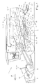
- FIG. 3 the rear region of the plan view of a combine harvester 1 with a distribution device 48 designed as a radial fan 90, which is arranged downstream of the straw chopper (not shown).
- the radial fan 90 consists of two juxtaposed rotors 91 which rotate in opposite directions about parallel axes of rotation 92.
- Each rotor 91 is disposed in a housing 93 having a lower-side lid 94 and a circumference of the respective one Rotor 91 encompassing wall 95, wherein in the wall 95, an outlet opening 96 is provided, which is followed by a radial discharge channel 97.
- the housing 93 are each driven by an actuator 98 about the axis of rotation 92 of the associated rotor 91 oscillating, so that the position the discharge channels 97 changes continuously.
- the actuators 98 are connected to the control unit 61, which transmits the control signals Y, Z dependent on the corresponding adjustment range 62, 63 to the actuators 98 and thus defines the stops for the discharge channels 97, through which the distribution width 64 of the outlet from the radial blower 90 Good current 99 is specified on the field,
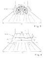
- FIG 4 the rear area of a top view of a combine harvester 1 is shown with a distribution device 48 designed as a distribution hood 103, which is arranged downstream of the straw chopper (not shown).
- a distribution device 48 designed as a distribution hood 103, which is arranged downstream of the straw chopper (not shown).
- a cover plate 104 a plurality of baffles 105 are arranged, which are mounted at its end facing the straw chopper pivotally mounted on the cover plate 104.
- the baffles 105 are connected to each other via a coupling mechanism 106 and are pivoted together via a hinged to the coupling mechanism 106 actuator 107.
- the actuator 107 is connected to the control unit 61, which transmits the control signal Y, Z dependent on the corresponding adjustment range 62, 63 to the actuator 107 and thus defines the pivot angle of the baffles 105 and thus the distribution width 64 of the output from the distribution hood 103 Gutstroms 108th determined on the field.
- the edge detection device 50 as a pushbutton, which is deflected when the contact edge 60, 65 is touched.
Landscapes
- Life Sciences & Earth Sciences (AREA)
- Environmental Sciences (AREA)
- Threshing Machine Elements (AREA)
- Combines (AREA)
- Guiding Agricultural Machines (AREA)
Claims (17)
- Machine de récolte pourvue d'un dispositif d'éparpillage pour un flux de produit sortant de la machine de récolte, le dispositif d'éparpillage comportant des éléments de guidage de produit réglables pour régler la largeur d'éparpillage du flux de produit, et la machine de récolte comportant un dispositif de détection de bord qui génère des signaux de distance en fonction de la position d'une récolte et/ou d'un champ récolté par rapport à la machine de récolte, caractérisée en ce que le réglage de la largeur d'éparpillage (64) du dispositif d'éparpillage (48) est effectué en fonction des signaux de distance (ES, ES1) du dispositif de détection de bord (50, 51, 67).
- Machine de récolte selon la revendication 1, caractérisée en ce que le dispositif de détection de bord (50) est un dispositif de localisation (51, 67) qui détecte sans contact un bord de récolte (60, 65) sur le champ.
- Machine de récolte selon au moins l'une des revendications précédentes, caractérisée en ce que le dispositif de localisation (51, 67) est relié à une unité d'évaluation (59), les signaux de distance (ES, ES1) étant transmis à l'unité d'évaluation (59).
- Machine de récolte selon au moins l'une des revendications précédentes, caractérisée en ce que l'unité d'évaluation (59) détermine à l'aide des signaux de distance (ES, ES1) si la récolte (57) se trouve à gauche ou à droite du bord de récolte (60) et génère un signal « gauche » (LS) quand la récolte (57) est disposée à gauche du bord de récolte (60) et un signal « droite » (RS) quand la récolte (57) est disposée à droite du bord de récolte (60).
- Machine de récolte selon au moins l'une des revendications précédentes, caractérisée en ce que l'unité d'évaluation (59) est reliée à une unité de commande (61), et l'unité d'évaluation (59) transmet le signal gauche (LS) et/ou le signal droite (RS) à l'unité de commande (61).
- Machine de récolte selon au moins l'une des revendications précédentes, caractérisée en ce qu'une première plage de réglage (62) pour régler la largeur d'éparpillage (64) et une deuxième plage de réglage (63) pour régler la largeur d'éparpillage (64) sont stockées dans l'unité de commande (61), et en ce que l'unité de commande (61) définit la première plage de réglage (62) en fonction du signal gauche (LS) et/ou la deuxième plage de réglage (63) en fonction du signal droite (RS).
- Machine de récolte selon au moins l'une des revendications précédentes, caractérisée en ce que l'unité de commande (61) génère des signaux de commande (Y, Z) en fonction de la plage de réglage (62, 63) définie, les butées ou l'angle de pivotement des éléments de guidage de produit (80, 97, 105) étant définis par les signaux de commande (Y, Z).
- Machine de récolte selon au moins l'une des revendications précédentes, caractérisée en ce que la machine de récolte est une moissonneuse-batteuse (1) et le dispositif d'éparpillage (48) est un éparpilleur de balle et/ou de matière broyée.
- Machine de récolte selon au moins l'une des revendications précédentes, caractérisée en ce que le dispositif d'éparpillage (48) est un capot éparpilleur (103) comportant au moins une tôle déflectrice pivotante (105), le signal de commande (Y, Z) généré par l'unité de commande (61) limitant l'angle de pivotement de la tôle déflectrice (105).
- Machine de récolte selon au moins l'une des revendications précédentes, caractérisée en ce que le dispositif d'éparpillage (48) comporte au moins une soufflante d'éjection (70) avec un bord de fuite pivotant (87), le signal de commande (Y, Z) généré par l'unité de commande (61) limitant les butées du bord de fuite (87).
- Machine de récolte selon au moins l'une des revendications précédentes, caractérisée en ce que le dispositif d'éparpillage (48) est une soufflante radiale (90) avec au moins un canal de décharge oscillant (97), le signal de commande (Y, Z) généré par l'unité de commande (61) limitant les butées du canal de décharge (97).
- Machine de récolte selon au moins l'une des revendications précédentes, caractérisée en ce que la machine de récolte comporte au moins deux dispositifs de localisation (51) qui génèrent chacun des signaux de distance (ES, ES1).
- Machine de récolte selon au moins l'une des revendications précédentes caractérisée en ce que les dispositifs de localisation (51) sont reliés à l'unité d'évaluation (59), et les dispositifs de localisation (51) transmettent les signaux de distance (ES, ES1) à l'unité de commande (59).
- Machine de récolte selon au moins l'une des revendications précédentes, caractérisée en ce que l'unité d'évaluation (59) est reliée à un élément de commande (66) au moyen duquel un opérateur sélectionne avec quels signaux de distance (ES, ES1) est définie la plage de réglage (62, 63) de l'élément de guidage de produit.
- Machine de récolte selon au moins l'une des revendications précédentes, caractérisée en ce que le dispositif de localisation (51, 67) est formé par un dispositif de localisation à réflexion.
- Machine de récolte selon au moins l'une des revendications précédentes, caractérisée en ce que le dispositif de localisation à réflexion fonctionne par laser, ultrasons ou infrarouges.
- Machine de récolte selon au moins l'une des revendications précédentes, caractérisée en ce que le dispositif de détection de bord (50) est un palpeur qui est dévié lors du contact avec le bord de récolte (60, 65).
Applications Claiming Priority (1)
| Application Number | Priority Date | Filing Date | Title |
|---|---|---|---|
| DE102005056553A DE102005056553A1 (de) | 2005-11-25 | 2005-11-25 | Verteileinrichtung für Gutstrom |
Publications (2)
| Publication Number | Publication Date |
|---|---|
| EP1790207A1 EP1790207A1 (fr) | 2007-05-30 |
| EP1790207B1 true EP1790207B1 (fr) | 2009-11-25 |
Family
ID=37709629
Family Applications (1)
| Application Number | Title | Priority Date | Filing Date |
|---|---|---|---|
| EP06120088A Not-in-force EP1790207B1 (fr) | 2005-11-25 | 2006-09-05 | Moissonneuse |
Country Status (3)
| Country | Link |
|---|---|
| EP (1) | EP1790207B1 (fr) |
| AT (1) | ATE449535T1 (fr) |
| DE (2) | DE102005056553A1 (fr) |
Cited By (5)
| Publication number | Priority date | Publication date | Assignee | Title |
|---|---|---|---|---|
| US11758847B2 (en) | 2019-09-19 | 2023-09-19 | Deere & Company | Residue quality assessment and performance system for a harvester |
| US12310285B2 (en) | 2023-02-27 | 2025-05-27 | Deere & Company | Agricultural operation evaluation system and method |
| US12406387B2 (en) | 2019-07-19 | 2025-09-02 | Deere & Company | Crop residue based field operation adjustment |
| US12457934B2 (en) | 2023-01-09 | 2025-11-04 | Deere & Company | Residue sensing and cleaning system |
| US12550819B2 (en) | 2023-04-12 | 2026-02-17 | Deere & Company | Residue sensor protection on a harvester |
Families Citing this family (14)
| Publication number | Priority date | Publication date | Assignee | Title |
|---|---|---|---|---|
| SE531230C2 (sv) * | 2007-06-20 | 2009-01-27 | Rekordverken Ab | Skördetröska med utloppsfläktar |
| DE102008040128B4 (de) * | 2007-08-04 | 2016-04-28 | Deere & Company | Erntegutrestehäcksel und -verteilanordnung für einen Mähdrescher mit einem an die Kontur des Strohhäckslers angepassten Wurfgebläse |
| DE102007037485B3 (de) * | 2007-08-08 | 2009-01-22 | Deere & Company, Moline | Mähdrescher mit einem Strohhäcksler, zwei Wurfgebläsen und einem sich kontinuierlich bewegenden Gutstromtrennelement |
| DE102009011094A1 (de) * | 2009-03-03 | 2010-09-09 | Claas Selbstfahrende Erntemaschinen Gmbh | Gutverteileinrichtung für Mähdrescher |
| EP2266381A1 (fr) * | 2009-06-23 | 2010-12-29 | Agro-Ingenjör AB | Dissipateur amélioré pour étaler les résidus de paille et de récolte |
| DE102013109983A1 (de) * | 2013-09-11 | 2015-03-12 | Claas Selbstfahrende Erntemaschinen Gmbh | Mähdrescher mit einer Abscheidevorrichtung |
| DE202014102621U1 (de) * | 2014-06-05 | 2015-06-11 | Heuling Maschinenbau Gmbh & Co. Kg | Verteileinrichtung für Häcksler an einem Mähdrescher |
| DE102014113965A1 (de) | 2014-09-26 | 2016-03-31 | Claas Selbstfahrende Erntemaschinen Gmbh | Mähdrescher mit Fahrerassistenzsystem |
| DE102016118187A1 (de) | 2016-09-27 | 2018-03-29 | Claas Selbstfahrende Erntemaschinen Gmbh | Mähdrescher mit Fahrerassistenzsystem |
| DE102017108761A1 (de) | 2017-04-25 | 2018-10-25 | Claas Selbstfahrende Erntemaschinen Gmbh | Mähdrescher |
| DE102018102594A1 (de) * | 2018-02-06 | 2019-08-08 | Claas Selbstfahrende Erntemaschinen Gmbh | Mähdrescher |
| GB202107135D0 (en) | 2021-05-19 | 2021-06-30 | Agco Int Gmbh | Residue spread monitoring |
| GB202108227D0 (en) | 2021-06-09 | 2021-07-21 | Agco Int Gmbh | Residue spread mapping |
| GB202108226D0 (en) | 2021-06-09 | 2021-07-21 | Agco Int Gmbh | Residue spread monitoring |
Family Cites Families (7)
| Publication number | Priority date | Publication date | Assignee | Title |
|---|---|---|---|---|
| DE4419421C2 (de) * | 1994-06-03 | 1996-03-28 | Claas Ohg | Verteilvorrichtung für Häcksler |
| DE19508942A1 (de) * | 1995-03-13 | 1996-09-19 | Claas Ohg | Reflex-Ortungsvorrichtung |
| DE10130665A1 (de) * | 2001-06-28 | 2003-01-23 | Deere & Co | Vorrichtung zur Messung der Menge von auf einem Feld stehenden Pflanzen |
| DE10134141A1 (de) * | 2001-07-13 | 2003-02-06 | Deere & Co | Verteilvorrichtung für aus einer Erntemaschine austretendes Häckselgut |
| DE10204702A1 (de) * | 2002-02-05 | 2003-08-14 | Claas Selbstfahr Erntemasch | Ortungssystem an selbstfahrenden landwirtschaftlichen Arbeitsmaschinen |
| DE10214648A1 (de) * | 2002-04-02 | 2003-10-16 | Claas Selbstfahr Erntemasch | Messeinrichtung an einer landwirtschaftlichen Maschine |
| DE10342922A1 (de) * | 2003-09-15 | 2005-05-19 | Claas Selbstfahrende Erntemaschinen Gmbh | Häcksel- und Verteilvorrichtung |
-
2005
- 2005-11-25 DE DE102005056553A patent/DE102005056553A1/de not_active Withdrawn
-
2006
- 2006-09-05 DE DE502006005448T patent/DE502006005448D1/de active Active
- 2006-09-05 EP EP06120088A patent/EP1790207B1/fr not_active Not-in-force
- 2006-09-05 AT AT06120088T patent/ATE449535T1/de active
Cited By (6)
| Publication number | Priority date | Publication date | Assignee | Title |
|---|---|---|---|---|
| US12406387B2 (en) | 2019-07-19 | 2025-09-02 | Deere & Company | Crop residue based field operation adjustment |
| US11758847B2 (en) | 2019-09-19 | 2023-09-19 | Deere & Company | Residue quality assessment and performance system for a harvester |
| US12035657B2 (en) | 2019-09-19 | 2024-07-16 | Deere & Company | Residue quality assessment and performance system for a harvester |
| US12457934B2 (en) | 2023-01-09 | 2025-11-04 | Deere & Company | Residue sensing and cleaning system |
| US12310285B2 (en) | 2023-02-27 | 2025-05-27 | Deere & Company | Agricultural operation evaluation system and method |
| US12550819B2 (en) | 2023-04-12 | 2026-02-17 | Deere & Company | Residue sensor protection on a harvester |
Also Published As
| Publication number | Publication date |
|---|---|
| DE502006005448D1 (de) | 2010-01-07 |
| ATE449535T1 (de) | 2009-12-15 |
| EP1790207A1 (fr) | 2007-05-30 |
| DE102005056553A1 (de) | 2007-05-31 |
Similar Documents
| Publication | Publication Date | Title |
|---|---|---|
| EP1790207B1 (fr) | Moissonneuse | |
| EP3662738B1 (fr) | Moissonneuse-batteuse automotrice | |
| EP1514466B1 (fr) | Dispositif de coupe et de distribution | |
| EP2298061B1 (fr) | Procédé de répartition d'un flux de matière sur un champ et dispositif de hachage et de répartition | |
| EP3000302B1 (fr) | Moissonneuse-batteuse equipée d'un dispositif de distribution | |
| EP1350424B1 (fr) | Moisonneuse-batteuse avec dispositif de guidage de paille motorisé ajustable | |
| DE602004000245T2 (de) | Ablenkungsplatte für einen Mähdrescherhäcksler | |
| EP1421843B1 (fr) | Moissonneuse-batteuse avec hache-paille | |
| EP1897430B1 (fr) | Dispositif de hachage et de répartition | |
| EP1862055B1 (fr) | Dispositif de répartition destiné à la répartition d'épinards sortant d'une hacheuse | |
| EP1656827A1 (fr) | Moissonneuse-batteuse avec hache-paille | |
| EP3000303A1 (fr) | Moissonneuse-batteuse dote d'un systeme d'assistance du conducteur | |
| DE10211800A1 (de) | Einrichtung zur Erfassung des Vorhandenseins eines Gutstroms in einer Erntemaschine | |
| EP2845461B1 (fr) | Agencement de mesure de perte dans une moissonneuse-batteuse | |
| EP2286654A1 (fr) | Agencement de hachage et de répartition de résidus de produits de récolte pour une moissonneuse-batteuse | |
| EP0349908B1 (fr) | Dispositif transporteur pour une moissonneuse | |
| EP2708107B1 (fr) | Moissonneuse-batteuse automotrice | |
| EP3662737B1 (fr) | Moissonneuse-batteuse automotrice | |
| DE60035635T2 (de) | Alarmsystem für landwirtschaftliche Maschinen | |
| EP3797577B1 (fr) | Moissonneuse-batteuse pourvue de capteur de grains restants | |
| EP2848113A1 (fr) | Dispositif de nettoyage pour une moissonneuse-batteuse | |
| DE102020123939A1 (de) | Rotierender siebkasten | |
| EP1470749B1 (fr) | Système batteur-séparateur | |
| DE102006023381A1 (de) | Verfahren und Vorrichtung zum Betreiben einer Erntegutzerkleinerungs- und -verteilvorrichtung | |
| DE10359398B3 (de) | Erntegutbergungseinrichtung mit Abstreifelementen |
Legal Events
| Date | Code | Title | Description |
|---|---|---|---|
| PUAI | Public reference made under article 153(3) epc to a published international application that has entered the european phase |
Free format text: ORIGINAL CODE: 0009012 |
|
| AK | Designated contracting states |
Kind code of ref document: A1 Designated state(s): AT BE BG CH CY CZ DE DK EE ES FI FR GB GR HU IE IS IT LI LT LU LV MC NL PL PT RO SE SI SK TR |
|
| AX | Request for extension of the european patent |
Extension state: AL BA HR MK YU |
|
| 17P | Request for examination filed |
Effective date: 20071130 |
|
| AKX | Designation fees paid |
Designated state(s): AT BE BG CH CY CZ DE DK EE ES FI FR GB GR HU IE IS IT LI LT LU LV MC NL PL PT RO SE SI SK TR |
|
| GRAP | Despatch of communication of intention to grant a patent |
Free format text: ORIGINAL CODE: EPIDOSNIGR1 |
|
| RTI1 | Title (correction) |
Free format text: HARVESTING MACHINE |
|
| RIN1 | Information on inventor provided before grant (corrected) |
Inventor name: DIEKHANS, DR. NORBERT |
|
| GRAS | Grant fee paid |
Free format text: ORIGINAL CODE: EPIDOSNIGR3 |
|
| GRAA | (expected) grant |
Free format text: ORIGINAL CODE: 0009210 |
|
| AK | Designated contracting states |
Kind code of ref document: B1 Designated state(s): AT BE BG CH CY CZ DE DK EE ES FI FR GB GR HU IE IS IT LI LT LU LV MC NL PL PT RO SE SI SK TR |
|
| REG | Reference to a national code |
Ref country code: GB Ref legal event code: FG4D Free format text: NOT ENGLISH |
|
| REG | Reference to a national code |
Ref country code: CH Ref legal event code: EP |
|
| REG | Reference to a national code |
Ref country code: IE Ref legal event code: FG4D |
|
| REF | Corresponds to: |
Ref document number: 502006005448 Country of ref document: DE Date of ref document: 20100107 Kind code of ref document: P |
|
| REG | Reference to a national code |
Ref country code: DE Ref legal event code: R096 Ref document number: 502006005448 Country of ref document: DE Effective date: 20100107 |
|
| REG | Reference to a national code |
Ref country code: NL Ref legal event code: VDEP Effective date: 20091125 |
|
| LTIE | Lt: invalidation of european patent or patent extension |
Effective date: 20091125 |
|
| PG25 | Lapsed in a contracting state [announced via postgrant information from national office to epo] |
Ref country code: IS Free format text: LAPSE BECAUSE OF FAILURE TO SUBMIT A TRANSLATION OF THE DESCRIPTION OR TO PAY THE FEE WITHIN THE PRESCRIBED TIME-LIMIT Effective date: 20100325 Ref country code: SE Free format text: LAPSE BECAUSE OF FAILURE TO SUBMIT A TRANSLATION OF THE DESCRIPTION OR TO PAY THE FEE WITHIN THE PRESCRIBED TIME-LIMIT Effective date: 20091125 Ref country code: PT Free format text: LAPSE BECAUSE OF FAILURE TO SUBMIT A TRANSLATION OF THE DESCRIPTION OR TO PAY THE FEE WITHIN THE PRESCRIBED TIME-LIMIT Effective date: 20100325 Ref country code: FI Free format text: LAPSE BECAUSE OF FAILURE TO SUBMIT A TRANSLATION OF THE DESCRIPTION OR TO PAY THE FEE WITHIN THE PRESCRIBED TIME-LIMIT Effective date: 20091125 Ref country code: LT Free format text: LAPSE BECAUSE OF FAILURE TO SUBMIT A TRANSLATION OF THE DESCRIPTION OR TO PAY THE FEE WITHIN THE PRESCRIBED TIME-LIMIT Effective date: 20091125 |
|
| PG25 | Lapsed in a contracting state [announced via postgrant information from national office to epo] |
Ref country code: SI Free format text: LAPSE BECAUSE OF FAILURE TO SUBMIT A TRANSLATION OF THE DESCRIPTION OR TO PAY THE FEE WITHIN THE PRESCRIBED TIME-LIMIT Effective date: 20091125 Ref country code: PL Free format text: LAPSE BECAUSE OF FAILURE TO SUBMIT A TRANSLATION OF THE DESCRIPTION OR TO PAY THE FEE WITHIN THE PRESCRIBED TIME-LIMIT Effective date: 20091125 Ref country code: CY Free format text: LAPSE BECAUSE OF FAILURE TO SUBMIT A TRANSLATION OF THE DESCRIPTION OR TO PAY THE FEE WITHIN THE PRESCRIBED TIME-LIMIT Effective date: 20091125 Ref country code: LV Free format text: LAPSE BECAUSE OF FAILURE TO SUBMIT A TRANSLATION OF THE DESCRIPTION OR TO PAY THE FEE WITHIN THE PRESCRIBED TIME-LIMIT Effective date: 20091125 |
|
| REG | Reference to a national code |
Ref country code: IE Ref legal event code: FD4D |
|
| PG25 | Lapsed in a contracting state [announced via postgrant information from national office to epo] |
Ref country code: BG Free format text: LAPSE BECAUSE OF FAILURE TO SUBMIT A TRANSLATION OF THE DESCRIPTION OR TO PAY THE FEE WITHIN THE PRESCRIBED TIME-LIMIT Effective date: 20100225 Ref country code: IE Free format text: LAPSE BECAUSE OF FAILURE TO SUBMIT A TRANSLATION OF THE DESCRIPTION OR TO PAY THE FEE WITHIN THE PRESCRIBED TIME-LIMIT Effective date: 20091125 Ref country code: RO Free format text: LAPSE BECAUSE OF FAILURE TO SUBMIT A TRANSLATION OF THE DESCRIPTION OR TO PAY THE FEE WITHIN THE PRESCRIBED TIME-LIMIT Effective date: 20091125 Ref country code: NL Free format text: LAPSE BECAUSE OF FAILURE TO SUBMIT A TRANSLATION OF THE DESCRIPTION OR TO PAY THE FEE WITHIN THE PRESCRIBED TIME-LIMIT Effective date: 20091125 Ref country code: EE Free format text: LAPSE BECAUSE OF FAILURE TO SUBMIT A TRANSLATION OF THE DESCRIPTION OR TO PAY THE FEE WITHIN THE PRESCRIBED TIME-LIMIT Effective date: 20091125 Ref country code: DK Free format text: LAPSE BECAUSE OF FAILURE TO SUBMIT A TRANSLATION OF THE DESCRIPTION OR TO PAY THE FEE WITHIN THE PRESCRIBED TIME-LIMIT Effective date: 20091125 Ref country code: ES Free format text: LAPSE BECAUSE OF FAILURE TO SUBMIT A TRANSLATION OF THE DESCRIPTION OR TO PAY THE FEE WITHIN THE PRESCRIBED TIME-LIMIT Effective date: 20100308 |
|
| PG25 | Lapsed in a contracting state [announced via postgrant information from national office to epo] |
Ref country code: SK Free format text: LAPSE BECAUSE OF FAILURE TO SUBMIT A TRANSLATION OF THE DESCRIPTION OR TO PAY THE FEE WITHIN THE PRESCRIBED TIME-LIMIT Effective date: 20091125 Ref country code: CZ Free format text: LAPSE BECAUSE OF FAILURE TO SUBMIT A TRANSLATION OF THE DESCRIPTION OR TO PAY THE FEE WITHIN THE PRESCRIBED TIME-LIMIT Effective date: 20091125 |
|
| PLBE | No opposition filed within time limit |
Free format text: ORIGINAL CODE: 0009261 |
|
| STAA | Information on the status of an ep patent application or granted ep patent |
Free format text: STATUS: NO OPPOSITION FILED WITHIN TIME LIMIT |
|
| PG25 | Lapsed in a contracting state [announced via postgrant information from national office to epo] |
Ref country code: GR Free format text: LAPSE BECAUSE OF FAILURE TO SUBMIT A TRANSLATION OF THE DESCRIPTION OR TO PAY THE FEE WITHIN THE PRESCRIBED TIME-LIMIT Effective date: 20100226 |
|
| 26N | No opposition filed |
Effective date: 20100826 |
|
| REG | Reference to a national code |
Ref country code: DE Ref legal event code: R097 Ref document number: 502006005448 Country of ref document: DE Effective date: 20100826 |
|
| PG25 | Lapsed in a contracting state [announced via postgrant information from national office to epo] |
Ref country code: IT Free format text: LAPSE BECAUSE OF FAILURE TO SUBMIT A TRANSLATION OF THE DESCRIPTION OR TO PAY THE FEE WITHIN THE PRESCRIBED TIME-LIMIT Effective date: 20091125 |
|
| PG25 | Lapsed in a contracting state [announced via postgrant information from national office to epo] |
Ref country code: MC Free format text: LAPSE BECAUSE OF NON-PAYMENT OF DUE FEES Effective date: 20100930 |
|
| REG | Reference to a national code |
Ref country code: CH Ref legal event code: PL |
|
| PG25 | Lapsed in a contracting state [announced via postgrant information from national office to epo] |
Ref country code: LI Free format text: LAPSE BECAUSE OF NON-PAYMENT OF DUE FEES Effective date: 20100930 Ref country code: CH Free format text: LAPSE BECAUSE OF NON-PAYMENT OF DUE FEES Effective date: 20100930 |
|
| PG25 | Lapsed in a contracting state [announced via postgrant information from national office to epo] |
Ref country code: HU Free format text: LAPSE BECAUSE OF FAILURE TO SUBMIT A TRANSLATION OF THE DESCRIPTION OR TO PAY THE FEE WITHIN THE PRESCRIBED TIME-LIMIT Effective date: 20100526 Ref country code: LU Free format text: LAPSE BECAUSE OF NON-PAYMENT OF DUE FEES Effective date: 20100905 |
|
| PG25 | Lapsed in a contracting state [announced via postgrant information from national office to epo] |
Ref country code: TR Free format text: LAPSE BECAUSE OF FAILURE TO SUBMIT A TRANSLATION OF THE DESCRIPTION OR TO PAY THE FEE WITHIN THE PRESCRIBED TIME-LIMIT Effective date: 20091125 |
|
| REG | Reference to a national code |
Ref country code: AT Ref legal event code: MM01 Ref document number: 449535 Country of ref document: AT Kind code of ref document: T Effective date: 20110905 |
|
| PG25 | Lapsed in a contracting state [announced via postgrant information from national office to epo] |
Ref country code: AT Free format text: LAPSE BECAUSE OF NON-PAYMENT OF DUE FEES Effective date: 20110905 |
|
| REG | Reference to a national code |
Ref country code: FR Ref legal event code: PLFP Year of fee payment: 11 |
|
| REG | Reference to a national code |
Ref country code: FR Ref legal event code: PLFP Year of fee payment: 12 |
|
| REG | Reference to a national code |
Ref country code: FR Ref legal event code: PLFP Year of fee payment: 13 |
|
| P01 | Opt-out of the competence of the unified patent court (upc) registered |
Effective date: 20230515 |
|
| PGFP | Annual fee paid to national office [announced via postgrant information from national office to epo] |
Ref country code: GB Payment date: 20230920 Year of fee payment: 18 |
|
| PGFP | Annual fee paid to national office [announced via postgrant information from national office to epo] |
Ref country code: FR Payment date: 20230928 Year of fee payment: 18 Ref country code: DE Payment date: 20230920 Year of fee payment: 18 Ref country code: BE Payment date: 20230920 Year of fee payment: 18 |
|
| REG | Reference to a national code |
Ref country code: DE Ref legal event code: R119 Ref document number: 502006005448 Country of ref document: DE |
|
| GBPC | Gb: european patent ceased through non-payment of renewal fee |
Effective date: 20240905 |
|
| PG25 | Lapsed in a contracting state [announced via postgrant information from national office to epo] |
Ref country code: DE Free format text: LAPSE BECAUSE OF NON-PAYMENT OF DUE FEES Effective date: 20250401 |
|
| PG25 | Lapsed in a contracting state [announced via postgrant information from national office to epo] |
Ref country code: GB Free format text: LAPSE BECAUSE OF NON-PAYMENT OF DUE FEES Effective date: 20240905 |
|
| REG | Reference to a national code |
Ref country code: BE Ref legal event code: MM Effective date: 20240930 |
|
| PG25 | Lapsed in a contracting state [announced via postgrant information from national office to epo] |
Ref country code: BE Free format text: LAPSE BECAUSE OF NON-PAYMENT OF DUE FEES Effective date: 20240930 |
|
| PG25 | Lapsed in a contracting state [announced via postgrant information from national office to epo] |
Ref country code: FR Free format text: LAPSE BECAUSE OF NON-PAYMENT OF DUE FEES Effective date: 20240930 |