EP1790274A2 - Steuersystem für einen Geschirrspüler mit mehreren Fächern - Google Patents
Steuersystem für einen Geschirrspüler mit mehreren Fächern Download PDFInfo
- Publication number
- EP1790274A2 EP1790274A2 EP06256087A EP06256087A EP1790274A2 EP 1790274 A2 EP1790274 A2 EP 1790274A2 EP 06256087 A EP06256087 A EP 06256087A EP 06256087 A EP06256087 A EP 06256087A EP 1790274 A2 EP1790274 A2 EP 1790274A2
- Authority
- EP
- European Patent Office
- Prior art keywords
- washing
- washing unit
- dishwasher
- primary
- outer housing
- Prior art date
- Legal status (The legal status is an assumption and is not a legal conclusion. Google has not performed a legal analysis and makes no representation as to the accuracy of the status listed.)
- Granted
Links
Images


Classifications
-
- A—HUMAN NECESSITIES
- A47—FURNITURE; DOMESTIC ARTICLES OR APPLIANCES; COFFEE MILLS; SPICE MILLS; SUCTION CLEANERS IN GENERAL
- A47L—DOMESTIC WASHING OR CLEANING; SUCTION CLEANERS IN GENERAL
- A47L15/00—Washing or rinsing machines for crockery or tableware
- A47L15/42—Details
- A47L15/46—Devices for the automatic control of the different phases of cleaning ; Controlling devices
-
- A—HUMAN NECESSITIES
- A47—FURNITURE; DOMESTIC ARTICLES OR APPLIANCES; COFFEE MILLS; SPICE MILLS; SUCTION CLEANERS IN GENERAL
- A47L—DOMESTIC WASHING OR CLEANING; SUCTION CLEANERS IN GENERAL
- A47L15/00—Washing or rinsing machines for crockery or tableware
- A47L15/0084—Washing or rinsing machines for crockery or tableware of drawer-type
Definitions
- the present invention pertains to the art of dishwashers and, more particularly, to a control system for a multi-compartment dishwasher.
- multi-compartment dishwashers are known in the art.
- a multi-compartment dishwasher includes multiple drawers or pull-out washing chambers slidably mounted in a cabinet.
- multi-compartment dishwashers that combine a pull-out washing chamber with a conventional type compartment.
- a dish rack is provided within each washing chamber to support dishware and the like during a washing operation.
- a washing operation can be performed in either one or both of the washing chambers.
- washing chambers typically are powered by a dedicated 15 amp circuit.
- power must be shared between the washing chambers.
- power sharing between the washing chambers does not pose any problems.
- Wash pumps, drain pumps and control elements do not, in most cases, have high power requirements:
- heating units for heating the washing fluid do have a high power requirement. Simultaneous operation of the heating units could cause the dishwasher to exceed the 15 amp circuit limit.
- each washing chamber requires special programming and/or dedicated electrical circuitry.
- some multi-compartment dishwashers are designed to share a common water supply. That is, the dishwasher includes a single water inlet valve that is bifurcated to feed each washing chamber during simultaneous operation. The valve is operated to fill one, then the other of the washing chambers.
- sharing a single fill valve requires additional programming for the control system.
- one chamber when sharing resources between multiple washing chambers, one chamber must be dominant over the other. More specifically, one chamber must be designated as a primary chamber and the other as a secondary chamber. The primary chamber receives initial access to system resources, while the secondary chamber must wait for the system resources to be allocated. In order to achieve this hierarchical relationship, even more programming and additional extensive wiring/circuitry is necessary.
- the present invention is directed to a multi-compartment dishwasher such as having first and second drawers slidably positioned in an outer housing.
- Each of the first and second drawers includes front, rear, bottom and opposing side walls that collectively define corresponding first and second washing tubs or chambers.
- the dishwasher also includes first and second control boards that are operatively associated with the first and second washing chambers respectively.
- the first and second control boards are joined by a communication link.
- the communication link serves as a conduit for sharing data between the control boards.
- the control boards are also linked to an ID designator that identifies one of the first and second washing tubs as a primary washing tub and the other of the first and second washing tubs as a secondary washing tub.
- the ID designator establishes a hierarchical relationship that enables the primary and secondary washing tubs to share system resources during an overall washing operation.
- the primary washing tub is initially allocated the system resources, while the secondary washing tub is in a delay or stand-by mode waiting for resources to be allocated. That is, the primary washing tub has preference over the secondary washing tub.
- Dishwasher 2 includes an outer housing (not shown) arranged below a kitchen countertop 6. Also below kitchen countertop 6 is shown cabinetry 8 including a plurality of drawers 9-12, as well as a cabinet door 13. Although the actual dishwasher into which the present invention may be incorporated can vary, the invention is shown in connection with dishwasher 2 depicted as a multi-compartment drawer-type dishwasher having an upper compartment 16 and a lower compartment 18.
- upper compartment 16 takes the form of a slide-out drawer unit having a small or medium capacity so as to be used for cleaning glassware and the like
- lower compartment 18 is illustrated as a larger capacity drawer for washing items such as dinnerware, cookware and other large sized objects.
- upper and lower compartments 16 and 18 could be of similar in size.
- dishwasher 2 could include a combination single pull-out drawer unit and a conventional dishwashing unit.
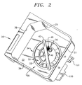
- Upper compartment 16 is shown to include a front wall 20, a rear wall 21, a bottom wall 22 and opposing side walls 23 and 24 that collectively define an upper washing unit or tub 28.
- Upper washing tub 28 is provided with a dish rack 30 for supporting various objects, such as glassware, utensils and the like, to be exposed to a washing operation.
- Upper compartment 16 is slidingly supported within the outer housing through a pair of extendible support guides, one of which is indicated at 31.
- bottom wall 22 actually forms part of a sump 32 that, as will be discussed more fully below, manages a flow of washing fluid within upper compartment 16.
- lower compartment 18 similarly includes front, rear, bottom and opposing side walls that collectively define a lower washing unit or tub 33.
- bottom wall 22 is provided with a recessed portion 34 having a generally U-shaped cross section that defines an intake ring 35.
- a coarse particle strainer 36 extends about recessed portion 34 to trap/prevent large soil particles from entering sump 32.
- coarse particle strainer 36 includes a plurality of openings, one of which is indicated at 37, provided with coarse filter screens (not shown) formed from, for example, a polyester mesh, plastic or stainless steel.
- the large soil particles trapped by coarse particle strainer 36 are ultimately collected in a coarse particle collection chamber 38, while other, smaller particles enter into sump 32 to ultimately collect in a fine particle collection chamber 40.
- a wash arm 42 that is rotatably supported upon a hub 46. In a manner known in the art, wash arm 42 emits jets of water and/or washing fluid that are directed onto the various objects supported on dish rack 30.
- sump 32 includes a plurality of fluid conduits 67-69 integrally formed along bottom wall 22 of washing tub 28.
- conduits 67-69 could be detachably secured to bottom wall 22.
- fluid conduit 67 constitutes a wash fluid supply conduit
- fluid conduit 68 constitutes a wash fluid recirculation conduit
- fluid conduit 69 constitutes a wash fluid drain conduit.
- Each of fluid conduits 67-69 provides wash fluid flow management during a washing operation.
- fluid conduits 67-69 are spaced from and arranged substantially parallel to one another on bottom wall 22, with conduits 67 and 69 extending from a central portion 71 of intake ring 35 to an outer edge portion 74 of washing tub 28.
- supply conduit 67 includes a first end 78 which is in fluid communication with wash arm 42 and leads to a second end 79 that is provided with an attachment flange 80.
- recirculation conduit 68 extends from a first end 81, which extends beyond intake ring 35 towards a front portion of compartment 16, to a second end 82.
- recirculation conduit 68 is provided with a corresponding attachment flange 83.
- drain conduit 69 extends from a first end 85 to a second end 86 which is also provided with an associated attachment flange 88.
- sump 32 serves as a mounting platform for a plurality of electrical wash system components which are generally represented at 100 in Figure 1.
- electrical wash system components 100 include a wash pump 110 and a drain pump 111 that are shown connected to washing tub 28 along outer edge portion 74.
- wash pump 110 includes a wash motor housing 115 and a wash pump housing 116.
- wash pump housing 116 includes an outlet 119 and an inlet 120 that conducts washing fluid back from washing tub 28 to pump housing 116.
- electrical wash system components 100 include a heater element 122 that is positioned within recirculation conduit 68. Heater element 122 is selectively activated to heat the washing fluid that is circulating into and out of washing tub 28 during a wash portion of the washing operation.
- lower washing tub 18 includes corresponding electrical wash system components as indicated at 150.
- dishwasher 2 includes a pair of control boards 180 and 190 that activate and manage the operation of electrical wash system components 100 and 150. More specifically, dishwasher 2 includes a first control board 180 operatively associated with washing operations in washing tub 28 and a second control board 190 operatively associated with washing operations in washing tub 33.
- control boards 180 and 190 could simply represent chips, or other forms of unit controllers. That is, based on inputs entered through a user interface controller 200, control boards 180 and 190 selectively activate wash system components 100 and 150 to establish washing operations in washing tubs 28 and 33 respectively.
- a consumer can select, through a plurality of control elements 220, a desired wash cycle and cycle options to be performed in one, the other or both of washing tubs 28 and 32.
- cycle and option selections, as well as wash/rinse cycle times remaining, are presented to the consumer on a display 240.
- first and second control boards 180 and 190 are joined by a communication link or bus 250.
- first and second control boards 180 and 190 receive signals from various sensors, such as temperature, turbidity, and the like sensors (not shown) through lines 252 and 253, with the number and type of sensors being model dependent.
- Communication bus 250 can take the form of a multi-drop bus, a peer to peer connection, a wireless link, or a serial or parallel connection. In any case, communication bus 250 enables first and second control boards 180 and 190 to share and communicate, i.e., both receive event data and broadcast status information, with user input controller 200, along with sharing other resources such as a common fill valve 260.
- first and second washing tubs 28 and 33 preferably share access to fill valve 260, in order to ensure efficient operating conditions, fill valve 260 is preferably controlled to only fill one washing tub 28 or 32 at a time. In this manner, a maximum flow of water is introduced to fill a selected washing tub 28 or 33, thereby allowing the start of a desired washing operation to occur in a short time period. Once filled, the washing operation can commence and, if selected, the other of washing tubs 28 and 33 is filled.
- first and second control boards 180 and 190 activate electric wash system components 100 and 150 in such a way so as to not overload a supply circuit.
- first and second control boards 180 and 190 preferably do not allow simultaneous activation of the heater elements 122 for washing tubs 28 and 33, at least in the case wherein activating heater elements 122 at the same time will exceed the current rating of the supply circuit.
- operation of shared resources is implemented through a control board hierarchy. That is, one of control boards 180 and 190 is designated as a master or primary control board, while the other of control boards 180 and 190 is designated as a slave or secondary control board as discussed more fully below.
- each control board 180, 190 is directly connected to system components 100, 150 respectively, the control board 180, 190 designated as the slave, for example control board 190 cannot activate one or more wash system components 150, e.g. respective heater element 122, if control board 180 has already activated other wash system components 100.
- control board 190 could not activate fill valve 260 if control board 180 has already initiated a fill in washing tub 28.
- dishwasher 2 includes first and second ID designators 300 and 320 that establish the hierarchy between first and second control boards 180 and 190 and, ultimately, first and second washing tubs 28 and 33.
- first and second ID designators 300 and 320 are arranged external to control boards 180 and 190, thus allowing the use of universal or identical control boards 180 and 190. That is, control boards 180 and 190 are substantially identical to one another in all respects, while a hierarchy is established between boards 180 and 190 through ID designators 300 and 320.
- ID designators 300 and 320 take the form of zero ohm jumpers, resistors of a known value, diodes or other like elements arranged in control circuitry.
- the primary or dominant control board for example, control board 180
- control board 180 is provided with preferential access to system resources.
- the primary control board 180 will signal fill valve 260 to first introduce water into the primary washing tub 28.
- the primary washing tub 28 will also be provide with preferential access to system resources, such as the respective heating element 122.
- the present invention advantageously allows the use of common or universal control boards 180 and 190 while still enabling a hierarchy to be readily established between compartments of a multi-compartment dishwasher.
- the invention advantageously allows multiple, individual dishwasher units or modules to be constructed, with the modules being useable alone or selectively interconnected to form an overall dishwasher 2 with a link established between control boards for each unit and one or more ID designators connected to the unit(s) to establish a preferred hierarchy.
Landscapes
- Washing And Drying Of Tableware (AREA)
Applications Claiming Priority (1)
| Application Number | Priority Date | Filing Date | Title |
|---|---|---|---|
| US11/288,289 US7363093B2 (en) | 2005-11-29 | 2005-11-29 | Control system for a multi-compartment dishwasher |
Publications (3)
| Publication Number | Publication Date |
|---|---|
| EP1790274A2 true EP1790274A2 (de) | 2007-05-30 |
| EP1790274A3 EP1790274A3 (de) | 2009-04-29 |
| EP1790274B1 EP1790274B1 (de) | 2012-02-22 |
Family
ID=37808352
Family Applications (1)
| Application Number | Title | Priority Date | Filing Date |
|---|---|---|---|
| EP06256087A Ceased EP1790274B1 (de) | 2005-11-29 | 2006-11-28 | Steuersystem für einen Geschirrspüler mit mehreren Fächern |
Country Status (2)
| Country | Link |
|---|---|
| US (1) | US7363093B2 (de) |
| EP (1) | EP1790274B1 (de) |
Cited By (8)
| Publication number | Priority date | Publication date | Assignee | Title |
|---|---|---|---|---|
| EP2127587A1 (de) * | 2008-05-31 | 2009-12-02 | Electrolux Home Products Corporation N.V. | Wasserauslaufsystem für eine Geschirrspülmaschine |
| EP2138087A1 (de) * | 2008-06-27 | 2009-12-30 | Electrolux Home Products Corporation N.V. | Geschirrspüler und Verfahren zum Einlassen von Wasser in einen Geschirrspüler |
| EP2138086A1 (de) * | 2008-06-27 | 2009-12-30 | Electrolux Home Products Corporation N.V. | Geschirrspüler und Verfahren zur Senkung der durch den Geschirrspüler erzeugten Geräusche |
| WO2010057792A2 (de) | 2008-11-19 | 2010-05-27 | BSH Bosch und Siemens Hausgeräte GmbH | Haushaltskältegerät |
| WO2017015256A1 (en) * | 2015-07-23 | 2017-01-26 | Illinois Tool Works Inc. | Dishwasher in the form of a commercial utensil washer or dishwasher which is designed as a batch dishwasher |
| US10405730B2 (en) | 2015-07-22 | 2019-09-10 | Illinois Tool Works Inc. | Dishwasher which is designed as a batch dishwasher |
| US10548455B2 (en) | 2014-03-13 | 2020-02-04 | Illinois Tool Works Inc. | Dishwasher in the form of a commercial utensil washer or dishwasher which is designed as a batch dishwasher |
| US11019980B2 (en) | 2018-08-24 | 2021-06-01 | Illinois Tool Works Inc. | Conveyor dishwashing machine, and method for operating a conveyor dishwashing machine |
Families Citing this family (26)
| Publication number | Priority date | Publication date | Assignee | Title |
|---|---|---|---|---|
| US9119515B2 (en) | 2010-12-03 | 2015-09-01 | Whirlpool Corporation | Dishwasher with unitary wash module |
| US8667974B2 (en) | 2009-12-21 | 2014-03-11 | Whirlpool Corporation | Rotating filter for a dishwashing machine |
| US9918609B2 (en) | 2009-12-21 | 2018-03-20 | Whirlpool Corporation | Rotating drum filter for a dishwashing machine |
| US8627832B2 (en) | 2010-12-13 | 2014-01-14 | Whirlpool Corporation | Rotating filter for a dishwashing machine |
| US9687135B2 (en) | 2009-12-21 | 2017-06-27 | Whirlpool Corporation | Automatic dishwasher with pump assembly |
| US8746261B2 (en) * | 2009-12-21 | 2014-06-10 | Whirlpool Corporation | Rotating drum filter for a dishwashing machine |
| US9113766B2 (en) | 2010-11-16 | 2015-08-25 | Whirlpool Corporation | Method and apparatus for dishwasher with common heating element for multiple treating chambers |
| US9668636B2 (en) | 2010-11-16 | 2017-06-06 | Whirlpool Corporation | Method and apparatus for dishwasher with common heating element for multiple treating chambers |
| US8043437B1 (en) | 2010-12-03 | 2011-10-25 | Whirlpool Corporation | Dishwasher with multiple treating chambers |
| US9034112B2 (en) | 2010-12-03 | 2015-05-19 | Whirlpool Corporation | Dishwasher with shared heater |
| US9107559B2 (en) | 2011-05-16 | 2015-08-18 | Whirlpool Corporation | Dishwasher with filter assembly |
| US8733376B2 (en) | 2011-05-16 | 2014-05-27 | Whirlpool Corporation | Dishwasher with filter assembly |
| US9265401B2 (en) | 2011-06-20 | 2016-02-23 | Whirlpool Corporation | Rotating filter for a dishwashing machine |
| US9005369B2 (en) | 2011-06-20 | 2015-04-14 | Whirlpool Corporation | Filter assembly for a dishwasher |
| US9861251B2 (en) | 2011-06-20 | 2018-01-09 | Whirlpool Corporation | Filter with artificial boundary for a dishwashing machine |
| US20120318296A1 (en) | 2011-06-20 | 2012-12-20 | Whirlpool Corporation | Ultra micron filter for a dishwasher |
| US9010344B2 (en) | 2011-06-20 | 2015-04-21 | Whirlpool Corporation | Rotating filter for a dishwashing machine |
| US9301667B2 (en) | 2012-02-27 | 2016-04-05 | Whirlpool Corporation | Soil chopping system for a dishwasher |
| US9237836B2 (en) | 2012-05-30 | 2016-01-19 | Whirlpool Corporation | Rotating filter for a dishwasher |
| US9730570B2 (en) | 2012-05-30 | 2017-08-15 | Whirlpool Corporation | Reduced sound with a rotating filter for a dishwasher |
| US9833120B2 (en) | 2012-06-01 | 2017-12-05 | Whirlpool Corporation | Heating air for drying dishes in a dishwasher using an in-line wash liquid heater |
| US9451862B2 (en) | 2012-06-01 | 2016-09-27 | Whirlpool Corporation | Dishwasher with unitary wash module |
| US9532700B2 (en) | 2012-06-01 | 2017-01-03 | Whirlpool Corporation | Dishwasher with overflow conduit |
| US9554688B2 (en) | 2012-10-23 | 2017-01-31 | Whirlpool Corporation | Rotating filter for a dishwasher and methods of cleaning a rotating filter |
| US12064076B2 (en) | 2019-08-16 | 2024-08-20 | Wylen Stone William Ford | Reusable drinking straw washing apparatus |
| US10945582B1 (en) * | 2019-10-24 | 2021-03-16 | Haier Us Appliance Solutions, Inc. | Consumer appliances and methods of operation |
Family Cites Families (14)
| Publication number | Priority date | Publication date | Assignee | Title |
|---|---|---|---|---|
| US3737862A (en) * | 1972-04-24 | 1973-06-05 | Instrument Systems Corp | Control system having column timers at each end |
| US4336462A (en) | 1978-05-26 | 1982-06-22 | Cyborex Laboratories, Inc. | Electrical load restoration system |
| US4245319A (en) | 1979-03-19 | 1981-01-13 | Cyborex Laboratories, Inc. | Energy management method and apparatus utilizing duty cycle reduction synchronized with the zero points of the applied voltage |
| US4703306A (en) * | 1986-09-26 | 1987-10-27 | The Maytag Company | Appliance system |
| DE69233238T2 (de) | 1991-12-20 | 2004-06-24 | Fisher + Paykel Appliances Ltd., East Tamaki | Geschirrspülmaschine |
| US5600310A (en) | 1994-12-02 | 1997-02-04 | General Electric Company | Serial bus control for appliances |
| CA2190307A1 (en) | 1995-11-21 | 1997-05-22 | Alan G. Outcalt | Dishwasher and control therefor |
| DE19615840A1 (de) | 1996-04-20 | 1997-10-30 | Bosch Gmbh Robert | Elektrisches Hausgerät |
| NZ314155A (en) | 1997-01-30 | 1999-07-29 | Fisher & Paykel | Dishwasher detergent dispenser located in door recess, having open top and being flushed out by overhead nozzle |
| US6795871B2 (en) * | 2000-12-22 | 2004-09-21 | General Electric Company | Appliance sensor and man machine interface bus |
| US7170405B2 (en) * | 2000-12-26 | 2007-01-30 | General Electric Company | Method and apparatus for interfacing a power line carrier and an appliance |
| US20030084928A1 (en) * | 2001-11-07 | 2003-05-08 | Wood John T. | Control for multiple compartment dishwasher |
| KR100440999B1 (ko) * | 2001-11-08 | 2004-07-21 | 삼성전자주식회사 | 가정자동화 시스템의 기동 제어장치 및 그 제어방법 |
| KR100496917B1 (ko) | 2002-09-05 | 2005-06-23 | 삼성전자주식회사 | 복합 가전기기 |
-
2005
- 2005-11-29 US US11/288,289 patent/US7363093B2/en not_active Expired - Fee Related
-
2006
- 2006-11-28 EP EP06256087A patent/EP1790274B1/de not_active Ceased
Cited By (16)
| Publication number | Priority date | Publication date | Assignee | Title |
|---|---|---|---|---|
| EP2127587A1 (de) * | 2008-05-31 | 2009-12-02 | Electrolux Home Products Corporation N.V. | Wasserauslaufsystem für eine Geschirrspülmaschine |
| EP2138087A1 (de) * | 2008-06-27 | 2009-12-30 | Electrolux Home Products Corporation N.V. | Geschirrspüler und Verfahren zum Einlassen von Wasser in einen Geschirrspüler |
| EP2138086A1 (de) * | 2008-06-27 | 2009-12-30 | Electrolux Home Products Corporation N.V. | Geschirrspüler und Verfahren zur Senkung der durch den Geschirrspüler erzeugten Geräusche |
| WO2010057792A2 (de) | 2008-11-19 | 2010-05-27 | BSH Bosch und Siemens Hausgeräte GmbH | Haushaltskältegerät |
| WO2010057792A3 (de) * | 2008-11-19 | 2010-07-22 | BSH Bosch und Siemens Hausgeräte GmbH | Haushaltskältegerät |
| US10548455B2 (en) | 2014-03-13 | 2020-02-04 | Illinois Tool Works Inc. | Dishwasher in the form of a commercial utensil washer or dishwasher which is designed as a batch dishwasher |
| US10548454B2 (en) | 2014-03-13 | 2020-02-04 | Illinois Tool Works Inc. | Dishwasher in the form of a commercial utensil washer or dishwasher which is designed as a batch dishwasher |
| US11000175B2 (en) | 2014-03-13 | 2021-05-11 | Illinois Tool Works Inc. | Dishwasher in the form of a commercial utensil washer or dishwasher which is designed as a batch dishwasher |
| US11627860B2 (en) | 2014-03-13 | 2023-04-18 | Illinois Tool Works Inc. | Dishwasher in the form of a commercial utensil washer or dishwasher which is designed as a batch dishwasher |
| US10405730B2 (en) | 2015-07-22 | 2019-09-10 | Illinois Tool Works Inc. | Dishwasher which is designed as a batch dishwasher |
| AU2016297533B2 (en) * | 2015-07-23 | 2018-06-21 | Illinois Tool Works Inc. | Dishwasher in the form of a commercial utensil washer or dishwasher which is designed as a batch dishwasher |
| WO2017015256A1 (en) * | 2015-07-23 | 2017-01-26 | Illinois Tool Works Inc. | Dishwasher in the form of a commercial utensil washer or dishwasher which is designed as a batch dishwasher |
| US10588477B2 (en) | 2015-07-23 | 2020-03-17 | Illinois Tools Works Inc. | Dishwasher in the form of a commercial utensil washer or dishwasher which is designed as a batch dishwasher |
| US10980392B2 (en) | 2015-07-23 | 2021-04-20 | Illinois Tool Works Inc. | Dishwasher in the form of a commercial utensil washer or dishwasher which is designed as a batch dishwasher |
| US11019980B2 (en) | 2018-08-24 | 2021-06-01 | Illinois Tool Works Inc. | Conveyor dishwashing machine, and method for operating a conveyor dishwashing machine |
| US11723507B2 (en) | 2018-08-24 | 2023-08-15 | Illinois Tool Works Inc. | Conveyor dishwashing machine, and method for operating a conveyor dishwashing machine |
Also Published As
| Publication number | Publication date |
|---|---|
| US20070124004A1 (en) | 2007-05-31 |
| EP1790274A3 (de) | 2009-04-29 |
| US7363093B2 (en) | 2008-04-22 |
| EP1790274B1 (de) | 2012-02-22 |
Similar Documents
| Publication | Publication Date | Title |
|---|---|---|
| EP1790274B1 (de) | Steuersystem für einen Geschirrspüler mit mehreren Fächern | |
| US8734595B2 (en) | Rapid heat system for a multi-tub dishwasher | |
| US7686890B2 (en) | Dishwasher control system | |
| US9743821B2 (en) | Dispenser for multi-compartment dishwasher | |
| US20120138106A1 (en) | Dishwasher with single valve to fill multiple compartments | |
| CN107580468B (zh) | 罩式批量洗碗机 | |
| US8157923B1 (en) | Method of reusing wash and rinse liquid in a dishwasher | |
| US9265398B2 (en) | Dishwasher with separate sump for concentrated fluid supply | |
| US20120138110A1 (en) | Dishwasher with auxiliary spray system having removable sprayers | |
| EP3308688B1 (de) | Geschirrspüler in form eines kommerziellen besteckwäschers oder geschirrspüler, der als chargengeschirrspüler designt ist | |
| US8038802B1 (en) | Reuse of wash liquid in dishwasher | |
| EP2127587A1 (de) | Wasserauslaufsystem für eine Geschirrspülmaschine | |
| US9532697B2 (en) | Dishwasher with unitary wash module | |
| US9655497B2 (en) | Dishwasher | |
| US9186034B2 (en) | Methods of reusing liquid in a dishwasher | |
| US20230250620A1 (en) | Configurable collaborative communal culinary workspaces | |
| US20060174923A1 (en) | Multi-use sump for a drawer-type dishwaher | |
| US6712082B2 (en) | Kitchenware washing apparatus | |
| US20210059498A1 (en) | Domestic appliance with at least one heater for a tubular piece through which a fluid flows | |
| US10126724B2 (en) | Low power management system | |
| DE102014101724A1 (de) | Verfahren und Vorrichtung für Geschirrspüler mit gemeinsamem Heizungselement für mehrere Behandlungskammern | |
| US10190249B2 (en) | Appliance control unit with arranged control switches |
Legal Events
| Date | Code | Title | Description |
|---|---|---|---|
| PUAI | Public reference made under article 153(3) epc to a published international application that has entered the european phase |
Free format text: ORIGINAL CODE: 0009012 |
|
| AK | Designated contracting states |
Kind code of ref document: A2 Designated state(s): AT BE BG CH CY CZ DE DK EE ES FI FR GB GR HU IE IS IT LI LT LU LV MC NL PL PT RO SE SI SK TR |
|
| AX | Request for extension of the european patent |
Extension state: AL BA HR MK YU |
|
| RIN1 | Information on inventor provided before grant (corrected) |
Inventor name: WERTHMAN, DEAN A. Inventor name: KING, JONATHAN D. |
|
| PUAL | Search report despatched |
Free format text: ORIGINAL CODE: 0009013 |
|
| AK | Designated contracting states |
Kind code of ref document: A3 Designated state(s): AT BE BG CH CY CZ DE DK EE ES FI FR GB GR HU IE IS IT LI LT LU LV MC NL PL PT RO SE SI SK TR |
|
| AX | Request for extension of the european patent |
Extension state: AL BA HR MK RS |
|
| AKX | Designation fees paid | ||
| 17P | Request for examination filed |
Effective date: 20090917 |
|
| RBV | Designated contracting states (corrected) |
Designated state(s): DE |
|
| REG | Reference to a national code |
Ref country code: DE Ref legal event code: 8566 |
|
| GRAP | Despatch of communication of intention to grant a patent |
Free format text: ORIGINAL CODE: EPIDOSNIGR1 |
|
| GRAS | Grant fee paid |
Free format text: ORIGINAL CODE: EPIDOSNIGR3 |
|
| GRAA | (expected) grant |
Free format text: ORIGINAL CODE: 0009210 |
|
| AK | Designated contracting states |
Kind code of ref document: B1 Designated state(s): DE |
|
| REG | Reference to a national code |
Ref country code: DE Ref legal event code: R082 Ref document number: 602006027737 Country of ref document: DE Representative=s name: DEHNS, GB |
|
| REG | Reference to a national code |
Ref country code: DE Ref legal event code: R096 Ref document number: 602006027737 Country of ref document: DE Effective date: 20120419 |
|
| PLBE | No opposition filed within time limit |
Free format text: ORIGINAL CODE: 0009261 |
|
| STAA | Information on the status of an ep patent application or granted ep patent |
Free format text: STATUS: NO OPPOSITION FILED WITHIN TIME LIMIT |
|
| 26N | No opposition filed |
Effective date: 20121123 |
|
| REG | Reference to a national code |
Ref country code: DE Ref legal event code: R097 Ref document number: 602006027737 Country of ref document: DE Effective date: 20121123 |
|
| PGFP | Annual fee paid to national office [announced via postgrant information from national office to epo] |
Ref country code: DE Payment date: 20161123 Year of fee payment: 11 |
|
| REG | Reference to a national code |
Ref country code: DE Ref legal event code: R119 Ref document number: 602006027737 Country of ref document: DE |
|
| PG25 | Lapsed in a contracting state [announced via postgrant information from national office to epo] |
Ref country code: DE Free format text: LAPSE BECAUSE OF NON-PAYMENT OF DUE FEES Effective date: 20180602 |