EP1790604A1 - Procédé et dispositif destinés au décollage de produits d'impression à partir d'un convoyeur - Google Patents
Procédé et dispositif destinés au décollage de produits d'impression à partir d'un convoyeur Download PDFInfo
- Publication number
- EP1790604A1 EP1790604A1 EP06405474A EP06405474A EP1790604A1 EP 1790604 A1 EP1790604 A1 EP 1790604A1 EP 06405474 A EP06405474 A EP 06405474A EP 06405474 A EP06405474 A EP 06405474A EP 1790604 A1 EP1790604 A1 EP 1790604A1
- Authority
- EP
- European Patent Office
- Prior art keywords
- saddle
- support shoulder
- lifting means
- printed product
- lifting
- Prior art date
- Legal status (The legal status is an assumption and is not a legal conclusion. Google has not performed a legal analysis and makes no representation as to the accuracy of the status listed.)
- Withdrawn
Links
- 238000000034 method Methods 0.000 title claims abstract description 15
- 230000000284 resting effect Effects 0.000 claims description 2
- 238000009434 installation Methods 0.000 abstract 2
- 239000002184 metal Substances 0.000 description 16
- 229910000831 Steel Inorganic materials 0.000 description 3
- 239000007787 solid Substances 0.000 description 3
- 239000010959 steel Substances 0.000 description 3
- 238000005259 measurement Methods 0.000 description 2
- 238000003462 Bender reaction Methods 0.000 description 1
- 240000007643 Phytolacca americana Species 0.000 description 1
- 229910000639 Spring steel Inorganic materials 0.000 description 1
- 238000009825 accumulation Methods 0.000 description 1
- 230000001419 dependent effect Effects 0.000 description 1
- 238000006073 displacement reaction Methods 0.000 description 1
- 238000007373 indentation Methods 0.000 description 1
- 238000010409 ironing Methods 0.000 description 1
Images


Classifications
-
- B—PERFORMING OPERATIONS; TRANSPORTING
- B42—BOOKBINDING; ALBUMS; FILES; SPECIAL PRINTED MATTER
- B42C—BOOKBINDING
- B42C1/00—Collating or gathering sheets combined with processes for permanently attaching together sheets or signatures or for interposing inserts
- B42C1/12—Machines for both collating or gathering and permanently attaching together the sheets or signatures
-
- B—PERFORMING OPERATIONS; TRANSPORTING
- B65—CONVEYING; PACKING; STORING; HANDLING THIN OR FILAMENTARY MATERIAL
- B65H—HANDLING THIN OR FILAMENTARY MATERIAL, e.g. SHEETS, WEBS, CABLES
- B65H3/00—Separating articles from piles
- B65H3/26—Separating articles from piles by separators engaging folds, flaps, or projections of articles
-
- B—PERFORMING OPERATIONS; TRANSPORTING
- B65—CONVEYING; PACKING; STORING; HANDLING THIN OR FILAMENTARY MATERIAL
- B65H—HANDLING THIN OR FILAMENTARY MATERIAL, e.g. SHEETS, WEBS, CABLES
- B65H39/00—Associating, collating, or gathering articles or webs
-
- B—PERFORMING OPERATIONS; TRANSPORTING
- B65—CONVEYING; PACKING; STORING; HANDLING THIN OR FILAMENTARY MATERIAL
- B65H—HANDLING THIN OR FILAMENTARY MATERIAL, e.g. SHEETS, WEBS, CABLES
- B65H2301/00—Handling processes for sheets or webs
- B65H2301/40—Type of handling process
- B65H2301/43—Gathering; Associating; Assembling
- B65H2301/436—Gathering; Associating; Assembling on saddles
-
- B—PERFORMING OPERATIONS; TRANSPORTING
- B65—CONVEYING; PACKING; STORING; HANDLING THIN OR FILAMENTARY MATERIAL
- B65H—HANDLING THIN OR FILAMENTARY MATERIAL, e.g. SHEETS, WEBS, CABLES
- B65H2301/00—Handling processes for sheets or webs
- B65H2301/40—Type of handling process
- B65H2301/44—Moving, forwarding, guiding material
- B65H2301/447—Moving, forwarding, guiding material transferring material between transport devices
- B65H2301/4471—Grippers, e.g. moved in paths enclosing an area
- B65H2301/44712—Grippers, e.g. moved in paths enclosing an area carried by chains or bands
Definitions
- the invention relates to an apparatus and a method for lifting folded printed products from a conveyor according to the preamble of the respective independent claims.
- the CH 683 767 A5 discloses a method for removing stapled and folded printed products from the pads of a saddle stitcher.
- the printed products are guided on a saddle-shaped, slightly built edition to a stapler.
- the pads have a comb-like support shoulder on which rest the folded printed products.
- the support shoulders have on the one hand recesses for Umbiegevortechnischen, which are aufstossbar from below to the support shoulders, and on the other hand recesses for Aushebestössel.
- the printed product is lifted by the Aushebestössel, which poke through more recesses of the support shoulder of the support shoulder and can be removed by, for example, a gripper. Due to the principle so must the Aushebestössel and the Umbiegevorides, seen along the support shoulder, be arranged at different locations. This limits the possibilities for arranging stapling points and gripping points.
- EP 0 202 507 A3 shows rod-shaped, thin pads, over which the printed products are hung.
- a Umbiegevorraum or anvil is guided from below against the pads and lifts the printed products from the pad.
- the printed products are now on the Umbiegevorraum and stapled.
- the Umbiegevorraum is led away again and the printed products are placed on the pads.
- a blade is guided past the thin support from below, so that the printed products are lifted and gripped by a pair of rollers.
- the accumulation conveyor has a retaining strip, which forms a ridge and is provided on both sides with support plates.
- the printed product lies with the fold over the retaining strip and the support plates.
- For lifting take-off fingers are pivoted through slots in the retaining strip, so that the printed products on the one hand lifted and on the other hand conveyed along the retaining strip.
- additional clamping devices can drive under the lifted printed product, lift it off the collecting conveyor and transport it away.
- a lifting means extends along the saddle and parallel to this and the lifting means is arranged offset in the transverse direction with respect to a support shoulder of the saddle and with respect to the counter-tool.
- the lifting means with respect to the support shoulder and in particular with respect to the counter tools are not arranged on a line but offset, a free arrangement of stapling points along the support shoulder is possible. There is no need to be concerned with the position of lifting racks or levers for lifting the printed products in the support shoulder.
- the support shoulder runs without recesses for a lifting means along the entire length of the saddle.
- the term "length" of the saddle refers here and below to the direction of maximum extension of the support shoulder, ie the direction parallel to the fold of the printed product.
- the transverse direction of the support shoulder is perpendicular to it. This transverse direction is in turn parallel to a longitudinal direction or conveying direction of a collection system in which the saddles are conveyed. It is also possible that the support shoulder runs completely without recesses along the entire length of the saddle.
- the saddle can be made correspondingly narrow, yet solid and stable.
- the counter tool for example a clincher for a stapler
- the counter tool is mounted movably in the support shoulder or fixedly connected to the support shoulder or even integrally formed on the support shoulder.
- Umbiegebalken several Umbieger can be arranged along the support shoulder, which can then also be referred to as Umbiegebalken.
- an upper edge of the lifting means runs along the entire length of the upper edge parallel to the support shoulder.
- an upper edge of the lift-off means extends in first regions parallel to the support shoulder, the print product being supported by these first regions during lift-off.
- the top edge has an offset or a depression or a depression relative to the first areas. This makes it possible to take in the region of this offset the printed product with a clamping means.
- the printed product can be grabbed with a gripper and transported away.
- a clamping device designed as a thickness measuring device. This thickness measurement may also be combined with gripping, i. that the gripper can both transport the printed product and measure its thickness.
- the printed product is not conveyed away in a preferred variant of the invention, but is lowered by the lifter back to the support shoulder and remains for error handling in the collection device.
- the lifting means is a flat plate, for example a sheet metal plate.
- the sheet metal plate nestles in a lower position on a side of the saddle, so that the contour of the saddle is not significantly changed by the adjacent sheet metal plate.
- the sheet metal plate is displaceable parallel in a sliding guide and is moved to lift the printed product parallel in an upper position.
- an upper edge of the sheet metal plate moves away from the saddle, and the printed product lies on this upper edge.
- the above-mentioned offset of the upper edge is preferably formed by a recess or indentation in the upper region of the plate.
- the lifting means is a wire bow.
- the wire bracket is guided in each case in the two longitudinal ends of the saddle in a parallel guide, which allows a parallel displacement perpendicular to the longitudinal direction of the support shoulder.
- In the central region along the saddle of the wire hanger runs either completely parallel to the support shoulder, or is offset in at least one area, as already explained above.
- the lifting means may be a flat plate whose upper edge pushes from the inside into the fold of the printed product. Also this plate can, according to the offset of the upper edge, have a recess whose position along the support shoulder corresponds to the position of a gripper or thickness gauge.
- the device has two lifting means.
- the first lifting means on a leading side of the saddle and the second lifting means on a trailing side of the saddle is arranged (with respect to the conveying direction or the transverse direction of the support shoulder).
- the upper edges of the two lifting means are preferably shaped differently, and in particular have one or more locations with an offset in different areas along the support shoulder.
- the lifter is moved to the appropriate position if necessary, so for stapling down or for gripping upwards.
- these operations such as collecting, stapling, gripping (including measuring) can be performed in any order.
- the lifter or lifters allow to bring the printed product in different positions, in which different tools can be activated. Certain operations require a certain position of the lifter, while other operations, especially collection, are basically possible at all positions of the lifter.
- Figures 1 and 2 show a perspective view of a saddle with a wire hanger as a lifter in a lower and in an upper position.
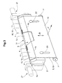
- Figure 3 shows a view with a metal plate as a lifter.
- the reference numerals used in the drawings and their meaning are listed in the list of reference numerals.
- FIG. 1 schematically shows a perspective view of a saddle 2 for conveying a printed product 1.
- the printed product 1 is folded and placed with the fold or back over a support shoulder 3 of the saddle 2.
- the support shoulder 3 has one or more counter tools such as clincher 4 for a stapler.
- the Umbieger 4 can be designed passive or active, so be yourself movable.
- the Umbieger 4 and the saddle 2 must be constructed correspondingly solid and stable. This is in contrast to saddles 2, which are intended only for conveying and are therefore designed to be light and thin.
- a clincher is moved to a stapling position, for example, by a stitching wheel for stapling.
- a lifter 5 is arranged.
- the lifter 5 extends along the longitudinal direction of the saddle 2 and the support shoulder 3, that is substantially parallel to these.
- the lifting device 5 is arranged offset with respect to the support shoulder 3.
- This transverse direction of the saddle 2 is in a collection system, which collects on a straight line, usually equal to the conveying direction F of the printed products 1.
- the lifter 5 can be arranged in the transverse direction or conveying direction F before or behind the support shoulder 3. From the saddle 2 extend, before and behind the support shoulder 3, sheets 12, 12 'made of spring steel substantially downwards.
- a lying on the support shoulder 3 printed product 1 is applied to the steel sheets 12, 12 '.
- the one or more lifters 5 are arranged on the inside of one of the steel sheets 12, 12 ', but on the outside of the support shoulder 3, ie between the saddle 2 and one of the steel sheets 12, 12'.
- the saddle 2 is mounted on brackets 27 in a conveyor track and is supported by not shown elements such as a chain on a rotating conveyor track through the collection system.
- the lifter 5 is drawn in a lower, inactive or home position
- the lifter 5 is drawn in an upper, active or raised position.
- a gripper 11 is shown by dashed lines.
- a strap end 7 acts as a control by shifting the lifter 5 against the force of a restoring spring 8 as required by a link on the conveyor track.
- the lifter 5 is displaced by a parallel guide 6 substantially parallel.
- the lifters 5 can also be moved in other ways.
- the lifter 5 is formed from a solid wire and has at least one offset 9 of the upper edge 10.
- the upper edge 10 has first, non-offset areas 22, 25, which push the fold of the printed product 1 from the inside upwards when lifting the printed product 1.
- the raised printed product 1 can be packed and transported away by a gripper 11, or the thickness of the printed product 1 can be measured without the siphon 5 influencing the measurement.
- the wire hanger preferably comprises: a first portion 21 and a sixth portion 26, each of which is perpendicular to the support shoulder 3 and each in an associated parallel guide 6, 6 'are displaceable, a second portion 22 and a fifth portion 25, each parallel to Support shoulder 3 run and are arranged collinear with each other, an offset portion 9 which is parallel to the support shoulder 3 and offset from the second 22 and fifth section 25, and a third portion 23 between the second portion 22 and the offset portion 9 and a fourth portion 24th between the offset portion 9 and the fifth portion 25.
- the lifter or lifters 5 are secured by means of a parallel guide 20, 20 ', in particular a sliding guide, on the saddle 2 and in a direction of movement B between a lower, adjacent position and an upper lift-off position.
- the movement is caused for example by a control such as a roller 7 'via a backdrop.
- the metal plate 15 has a main surface 19, which is substantially planar and with its surface forms part of the parallel guide 20 by the metal plate 15 slides along the saddle 2. At the lower part of the main surface, the control rollers 7 'are attached. At the upper part of the main surface 19, a support surface 17 of the metal plate 15 is bent by a bend 18 with respect to the main surface 19 to the edge 13 of the support shoulder 3 out. Thus, the sheet metal plate 15 is in the lower position close to the saddle 2.
- collinear support portions 16 are formed on one side, on which the printed product 1 is located when lifting with the inside of the fold.
- the product 1 which has been raised can be gripped in the region of the recess and / or its thickness can be measured.
- these recesses which lie in the direction along the support shoulder 3 at different locations.
Landscapes
- Engineering & Computer Science (AREA)
- Mechanical Engineering (AREA)
- Feeding Of Articles By Means Other Than Belts Or Rollers (AREA)
Applications Claiming Priority (1)
| Application Number | Priority Date | Filing Date | Title |
|---|---|---|---|
| CH18652005 | 2005-11-23 |
Publications (1)
| Publication Number | Publication Date |
|---|---|
| EP1790604A1 true EP1790604A1 (fr) | 2007-05-30 |
Family
ID=36051474
Family Applications (1)
| Application Number | Title | Priority Date | Filing Date |
|---|---|---|---|
| EP06405474A Withdrawn EP1790604A1 (fr) | 2005-11-23 | 2006-11-09 | Procédé et dispositif destinés au décollage de produits d'impression à partir d'un convoyeur |
Country Status (3)
| Country | Link |
|---|---|
| US (1) | US7628390B2 (fr) |
| EP (1) | EP1790604A1 (fr) |
| CA (1) | CA2568662A1 (fr) |
Families Citing this family (3)
| Publication number | Priority date | Publication date | Assignee | Title |
|---|---|---|---|---|
| JP2011520735A (ja) * | 2008-05-22 | 2011-07-21 | ゴス インターナショナル アメリカス インコーポレイテッド | グリッパコンベヤデリバリ |
| US8413977B2 (en) * | 2011-03-30 | 2013-04-09 | Mueller Martini Holding Ag | Device and method for delivering printed products from a saddle-shaped support |
| JP5794250B2 (ja) * | 2013-04-01 | 2015-10-14 | コニカミノルタ株式会社 | 後処理装置および画像形成装置 |
Citations (4)
| Publication number | Priority date | Publication date | Assignee | Title |
|---|---|---|---|---|
| EP0202507A2 (fr) * | 1985-05-22 | 1986-11-26 | Am International Incorporated | Transporteur d'assemblage |
| EP0218804A1 (fr) * | 1985-08-29 | 1987-04-22 | Ferag AG | Dispositif pour reprendre et transférer des feuilles pliées d'un dispositif de transport |
| CH683767A5 (de) * | 1993-03-12 | 1994-05-13 | Grapha Holding Ag | Verfahren zur Herstellung von Druckprodukten und Vorrichtung zur Durchführung desselben. |
| US20030161705A1 (en) * | 2002-02-28 | 2003-08-28 | Trovinger Steven W. | Pivotable collecting device |
Family Cites Families (3)
| Publication number | Priority date | Publication date | Assignee | Title |
|---|---|---|---|---|
| US4236706A (en) * | 1979-04-18 | 1980-12-02 | Harris Corporation | Signature conveyor for use with inserter and stitcher |
| US4260145A (en) * | 1979-05-04 | 1981-04-07 | Harris Corporation | Signature handling apparatus |
| CH662987A5 (de) * | 1984-01-26 | 1987-11-13 | Grapha Holding Ag | Sattelheftmaschine. |
-
2006
- 2006-11-09 EP EP06405474A patent/EP1790604A1/fr not_active Withdrawn
- 2006-11-20 US US11/561,637 patent/US7628390B2/en not_active Expired - Fee Related
- 2006-11-22 CA CA002568662A patent/CA2568662A1/fr not_active Abandoned
Patent Citations (4)
| Publication number | Priority date | Publication date | Assignee | Title |
|---|---|---|---|---|
| EP0202507A2 (fr) * | 1985-05-22 | 1986-11-26 | Am International Incorporated | Transporteur d'assemblage |
| EP0218804A1 (fr) * | 1985-08-29 | 1987-04-22 | Ferag AG | Dispositif pour reprendre et transférer des feuilles pliées d'un dispositif de transport |
| CH683767A5 (de) * | 1993-03-12 | 1994-05-13 | Grapha Holding Ag | Verfahren zur Herstellung von Druckprodukten und Vorrichtung zur Durchführung desselben. |
| US20030161705A1 (en) * | 2002-02-28 | 2003-08-28 | Trovinger Steven W. | Pivotable collecting device |
Also Published As
| Publication number | Publication date |
|---|---|
| US7628390B2 (en) | 2009-12-08 |
| CA2568662A1 (fr) | 2007-05-23 |
| US20070114710A1 (en) | 2007-05-24 |
Similar Documents
| Publication | Publication Date | Title |
|---|---|---|
| EP0346578B1 (fr) | Dispositif pour assembler, collationner et insérer des produits imprimés | |
| EP1232978B1 (fr) | Dispositif de transport pour assembler et transporter des feuilles imprimées déposées à cheval sur un premier convoyeur à chaine | |
| EP0341425A2 (fr) | Dispositif pour collationner des produits imprimés pliés | |
| DE3220495A1 (de) | Foerdervorrichtung fuer zuschnitte | |
| EP0366038B1 (fr) | Dispositif pour plier en zigzag et empiler une bande de matériau | |
| CH650729A5 (de) | Einrichtung fuer den transport und fuer das zusammenheften einer gruppe von schriftstuecken. | |
| EP2277812B1 (fr) | Procédé d'alignement latéral de produits ayant une surface de base plane, notamment de produits d'impression, et dispositif de transport destiné à l'exécution du procédé | |
| EP0916514B2 (fr) | Assembleuse et brocheuse combinées | |
| DE2414954A1 (de) | Einrichtung zum herstellen von luecken zwischen den von einem foerderer getragenen papierboegen | |
| EP0522319A1 (fr) | Procédé et dispositif pour ouvrir des articles flexible pliés hors du centre | |
| DE2800846C3 (de) | Vorrichtung zum Aufbringen von Abschlußblättern o.dgl. auf Blattlagen | |
| DE2508745C2 (de) | Vorrichtung zum Aufstauen vereinzelt mittels einer Transportvorrichtung zugeförderter Papierbögen zu Stapeln und zum Weitertransportieren dieser Stapel | |
| EP1939008B1 (fr) | Assembleuse et brocheuse dotée d'une chaîne variable | |
| CH656861A5 (de) | Vorrichtung zum lagern von papierbogen. | |
| DE4121190A1 (de) | Vorrichtung zum trennen und erfassen gestapelter blaetter | |
| EP0712736B1 (fr) | Méthode pour la fabrication de livres, brochures ou similaires reliés par adhésif | |
| EP0300171B1 (fr) | Dispositif de transport pour produits plats, en particulier des produits imprimés | |
| DE3039104C2 (de) | Vorrichtung zum Fördern von Blattstapeln, insbesondere für Buchbindereiwerkstätten | |
| EP4538204A1 (fr) | Dispositif de transport suspendu, installation de transport suspendu dotée d'un tel dispositif de transport suspendu et procédé de transport de marchandises | |
| DE2950617C2 (de) | Vorichtung zum schrittweisen Fördern von Papierstapeln | |
| DE2716904C3 (de) | Übergabeeinrichtung für rollbare Gegenstände | |
| DE202004010068U1 (de) | Wendevorrichtung zum Handhaben von Packungen aus gefalteten blattförmigen Produkten | |
| EP1566284B1 (fr) | Assembleuse et brocheuse avec une surface d'arrêt composée | |
| DE2542723C2 (de) | Vorrichtung zum Umsetzen eines Schuppenstromes aus Falzbogen in einen Falzbogenstapel | |
| EP1661833B1 (fr) | Procédé et dispositif pour traiter des produits imprimés |
Legal Events
| Date | Code | Title | Description |
|---|---|---|---|
| PUAI | Public reference made under article 153(3) epc to a published international application that has entered the european phase |
Free format text: ORIGINAL CODE: 0009012 |
|
| AK | Designated contracting states |
Kind code of ref document: A1 Designated state(s): AT BE BG CH CY CZ DE DK EE ES FI FR GB GR HU IE IS IT LI LT LU LV MC NL PL PT RO SE SI SK TR |
|
| AX | Request for extension of the european patent |
Extension state: AL BA HR MK YU |
|
| 17P | Request for examination filed |
Effective date: 20070912 |
|
| 17Q | First examination report despatched |
Effective date: 20071011 |
|
| AKX | Designation fees paid |
Designated state(s): AT BE BG CH CY CZ DE DK EE ES FI FR GB GR HU IE IS IT LI LT LU LV MC NL PL PT RO SE SI SK TR |
|
| GRAP | Despatch of communication of intention to grant a patent |
Free format text: ORIGINAL CODE: EPIDOSNIGR1 |
|
| RIC1 | Information provided on ipc code assigned before grant |
Ipc: B65H 5/32 20060101ALI20120702BHEP Ipc: B65H 3/26 20060101AFI20120702BHEP Ipc: B42C 1/00 20060101ALI20120702BHEP Ipc: B42C 1/12 20060101ALI20120702BHEP Ipc: B65H 39/00 20060101ALI20120702BHEP |
|
| STAA | Information on the status of an ep patent application or granted ep patent |
Free format text: STATUS: GRANT OF PATENT IS INTENDED |
|
| STAA | Information on the status of an ep patent application or granted ep patent |
Free format text: STATUS: THE APPLICATION IS DEEMED TO BE WITHDRAWN |
|
| 18D | Application deemed to be withdrawn |
Effective date: 20121213 |