EP1790760A2 - Unité de buse d'air pour réaliser un fil - Google Patents
Unité de buse d'air pour réaliser un fil Download PDFInfo
- Publication number
- EP1790760A2 EP1790760A2 EP06021802A EP06021802A EP1790760A2 EP 1790760 A2 EP1790760 A2 EP 1790760A2 EP 06021802 A EP06021802 A EP 06021802A EP 06021802 A EP06021802 A EP 06021802A EP 1790760 A2 EP1790760 A2 EP 1790760A2
- Authority
- EP
- European Patent Office
- Prior art keywords
- air
- annular exhaust
- opening
- duct
- supply air
- Prior art date
- Legal status (The legal status is an assumption and is not a legal conclusion. Google has not performed a legal analysis and makes no representation as to the accuracy of the status listed.)
- Granted
Links
Images
Classifications
-
- D—TEXTILES; PAPER
- D01—NATURAL OR MAN-MADE THREADS OR FIBRES; SPINNING
- D01H—SPINNING OR TWISTING
- D01H4/00—Open-end spinning machines or arrangements for imparting twist to independently moving fibres separated from slivers; Piecing arrangements therefor; Covering endless core threads with fibres by open-end spinning techniques
- D01H4/02—Open-end spinning machines or arrangements for imparting twist to independently moving fibres separated from slivers; Piecing arrangements therefor; Covering endless core threads with fibres by open-end spinning techniques imparting twist by a fluid, e.g. air vortex
-
- D—TEXTILES; PAPER
- D01—NATURAL OR MAN-MADE THREADS OR FIBRES; SPINNING
- D01H—SPINNING OR TWISTING
- D01H1/00—Spinning or twisting machines in which the product is wound-up continuously
- D01H1/11—Spinning by false-twisting
- D01H1/115—Spinning by false-twisting using pneumatic means
-
- D—TEXTILES; PAPER
- D01—NATURAL OR MAN-MADE THREADS OR FIBRES; SPINNING
- D01H—SPINNING OR TWISTING
- D01H5/00—Drafting machines or arrangements ; Threading of roving into drafting machine
- D01H5/18—Drafting machines or arrangements without fallers or like pinned bars
- D01H5/60—Arrangements maintaining drafting elements free of fibre accumulations
- D01H5/66—Suction devices exclusively
Definitions
- the invention relates to an air jet unit for producing a spun yarn with a swirling chamber and an annular exhaust air duct discharging the spinning air from the swirling chamber, which has a connection opening for a vacuum source, and with at least one supply air opening, which opens into the annular exhaust air duct.
- An air jet unit of this kind is by the DE 103 11 826 A1 State of the art.
- the known air jet unit is arranged downstream of a drafting roller having a delivery roller pair, wherein the pair of delivery rollers, a cleaning channel is associated with a suction opening, which serves to keep clean the delivery roller pair and sucks fiber fly from the peripheral surfaces of the delivery roller pair.
- the cleaning channel opens into the annular exhaust air duct.
- the cleaning channel and the annular exhaust duct are connected to a common vacuum source.
- annular exhaust channel which is arranged concentrically around a spindle-shaped component, which in turn contains a Garnabzugskanal through which the spun yarn is withdrawn, is often prone to deposits and blockages.
- the annular exhaust air duct is mainly used for discharging the spinning air from the vortex chamber. Although the spinning air flows at very high speed in the vortex chamber and generates the rotating at high speed air vortex, which gives the supplied fiber structure its spin rotation, however, is not very large due to the very small diameter of the compressed air nozzles, the incoming air. In the annular exhaust air duct adjoining the swirl chamber, which has cross-sectional enlargements, this leads to a strong decrease in the flow velocity.
- the slowing flow rate of the air reduces the air's ability to transport debris and fiber fly. These inevitably in the discharged from the vortex chamber Spinn Kunststoff contained impurities can thereby deposit in the annular exhaust duct and lead there over time to blockages. These deposits can lead to impairments up to interruptions of the spinning process.
- the areas in the annular exhaust duct, in which very small air flows are present and in which the deposits mainly occur, are also referred to as "dead spaces".
- the suction opening is associated with the delivery roller pair and which opens into the annular exhaust duct provided so passes additional fiber fly in the already vulnerable to blockages areas of the annular exhaust duct and thereby amplifies the frequency of interference very strong.
- the cleaning channel is at the same time a Zu Kunststoffö réelle, passes through the additional air in the annular exhaust duct and there partially increases the flow rate, however, is achieved by the impurities contained no positive effect.
- the supply air opening opens in the vicinity of the vortex chamber in the annular exhaust duct. In the end regions of the annular exhaust air channel facing away from the swirl chamber, there are still dead spaces in which deposits form.
- the invention is based on the object to improve an air jet unit of the type mentioned in terms of its reliability and to minimize malfunction due to deposits in the exhaust duct.
- the object is achieved in that the at least one supply air opening opens in an annular region remote from the connection opening in the annular exhaust duct.
- the supply air opening is arranged substantially opposite to the connection opening.
- the basis for this is the spindle-shaped component, which is surrounded by the annular exhaust air duct. Since supply air opening and connection opening are not necessarily arranged exactly radially on the annular exhaust air duct, the position of the transitional areas between the supply air opening or the connection opening and the annular exhaust air duct is decisive for achieving the positive effect.
- the transition region from the supply air opening into the annular exhaust air duct with respect to the spindle-shaped component is arranged substantially opposite the transition region from the annular exhaust air duct into the connection opening.
- a particularly susceptible area for deposits in the annular exhaust air duct is located in the end region of the annular exhaust air duct which faces away from the swirl chamber. It is advantageous if the transition region from the supply air opening into the annular exhaust air duct is arranged in this end region of the annular exhaust air duct and thus has the greatest possible distance from the air flow coming from the swirl chamber.
- the inlet region of the supply air opening at a point of the air nozzle unit connected to the free atmosphere at which the ambient air is relatively clean.
- the inlet region of the supply air opening should not be directly facing the drafting system. It can also be advantageous to provide shielding devices or a pipeline at the supply air opening in order to avoid aspiration of fiber fly.
- the supply air opening opens substantially in a plane perpendicular to the spun yarn in the annular exhaust duct.
- Such a supply air opening can be very easily produced on the air nozzle unit and has the effect that dead spaces in the regions of the annular exhaust air duct remote from the connection opening are eliminated.
- the arrangement of the supply air opening substantially perpendicular to the spun yarn has the advantage that the supply air outlet exits at a point from the air nozzle unit at which the air sucked contains hardly any impurities.
- the inlet area of the supply air opening is far enough away from the drafting system that usually generates the most fiber fly away.
- the aim of Zu Kunststoffö réelle is to direct additional clean air into the annular exhaust duct to increase there the flow velocity of the discharged from the vortex chamber spinning air and thereby improve the removal of dirt and prevent deposits.
- the supply air opening opens substantially tangentially into the annular exhaust air duct.
- the spinning air flowing out of the vortex chamber is thereby assisted in its rotation and it is avoided that the rotation of the air flow ceases too quickly and dirt particles carried in the air flow can settle.
- a connection opening for a vacuum source which is arranged on the annular exhaust air duct, extends substantially tangentially out of the annular exhaust air duct. This ensures that the air flow and the dirt particles contained therein do not undergo an abrupt change in direction, and instead can flow largely undisturbed from their rotating movement through the connection opening to the vacuum source.
- the supply air opening is arranged substantially opposite the connection opening for a vacuum source on the annular exhaust air duct.
- the free cross section of the supply air opening is adjustable.
- a throttle device such as a slide or the like, can be arranged in the inlet region of the inlet air opening. It may also be advantageous to couple the throttle device with an automatic adjusting device, which is connected to a control device and which adjusts or regulates the free cross section of the supply air opening according to other parameters on the air jet spinning device.
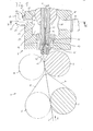
- the device shown in FIG. 1 is used to produce a spun yarn 1 from a staple fiber structure 2.
- the device contains as essential components a drafting arrangement 3 and an air jet unit 4.
- the to be spun staple fiber strand 2 is fed to the drafting 3 in the supply direction A and withdrawn as spun yarn 1 in the withdrawal direction B and forwarded to a winding device, not shown.
- the drafting system 3 shown only partially can be designed as a three- or four-cylinder drafting system and contains a plurality of pairs of rollers, each containing a driven lower roller and a trained as a pressure roller upper roller.
- the output of the drafting system 3 forms a delivery roller pair 9, 10.
- the reference numerals 5 and 9 are respectively driven lower rollers, denoted by the reference numerals 6 and 10, the associated pressure rollers.
- the staple fiber strand 2 is warped in a known manner to a desired fineness. Following the drafting system 3 then there is a thin fiber ribbon 11, which is stretched, but still untwisted.
- the fiber ribbon 11 is fed to the arranged after the drafting 3 air jet unit 4. It is immaterial for the present invention, whether the fiber ribbon 11 actually as shown, is generated by a drafting system 3 or not. Alternatively, other possibilities may be provided to produce such a thin fiber ribbon 11.
- the air jet unit 4 the fiber ribbon 11 is supplied via an inlet channel 12. It follows a so-called vortex chamber 13, in which the fiber ribbon 11, the spinning rotation is granted, so that the spun yarn 1 is formed, which is withdrawn through a Garnabzugskanal 14.
- a fluid device generates a rotating vortex flow in the vortex chamber 13 by blowing compressed air through compressed air nozzles 15 which open tangentially into the vortex chamber 13.
- the compressed air emerging from the compressed air nozzles 15 is discharged through an annular exhaust duct 16 which is formed in the manner of an annular channel with an annular cross-section around a spindle-shaped stationary member 17 which contains the Garnabzugskanal 14.
- the annular exhaust air duct 16 is via a connection opening 18 connected to a likewise shown as a channel and unspecified vacuum source 19.
- an edge of a fiber guide surface is arranged as a swirl barrier, which is arranged slightly eccentrically to the yarn withdrawal channel 14 in the region of its inlet opening. It should be noted at this point that the air nozzle unit 4 in the field of the vortex chamber 13 may be quite differently designed as shown here. Essential to the invention is only the annular exhaust duct 16.
- the fibers to be spun are held on the one hand in the fiber ribbon 11 and thus guided from the inlet channel 12 substantially without rotation in the Garnabzugskanal 14.
- the fibers in the region between the inlet channel 12 and the yarn withdrawal channel 14 are subjected to the action of the turbulent flow, by which they or at least their end regions are radially expelled from the inlet opening of the yarn withdrawal channel 14.
- the yarns 1 produced by the described method thereby exhibit a core of substantially longitudinally extending fibers or fiber regions without substantial rotation and an outer region in which the fibers or fiber regions are turned around the core.
- this thread construction is achieved by leading ends of fibers, in particular those whose trailing regions are still held upstream in the inlet channel, coming substantially directly into the yarn withdrawal channel 14, but that trailing fiber regions, especially if they are located in the entrance area of the yarn Inlet channel 12 are no longer held, pulled out by the vortex flow from the fiber ribbon 11 and then rotated about the resulting yarn 1.
- fibers are entrained in both the resulting yarn 1, thereby being pulled through the yarn withdrawal channel 14, as well as being exposed to the swirling flow, which accelerates them centrifugally, ie from the inlet opening of the yarn withdrawal channel 14 and into the annular exhaust air channel 16.
- the drawn by the vortex flow from the fiber ribbon 11 fiber regions form a opening into the inlet opening of Garnabzugskanals 14 fiber vortex whose longer portions rotate outside the spindle-shaped member 17 and are pulled against the force of flow in the annular exhaust duct 16 into the inlet opening of Garnabzugskanals 14.
- a device of this type allows particularly high spinning speeds, which may be on the order of 600 m / min. It may happen that individual fibers, fiber fragments or other dirt particles from the fiber ribbon 11 solve and are sucked into the annular exhaust duct 16.
- the air flow in the annular exhaust air duct 16 extends mainly from the swirl chamber 13 to the connection opening 18 and then to the vacuum source 19. Due to the structural reasons predetermined shape of the annular exhaust duct 16 is formed in particular in the side remote from the swirl chamber 13 end portion 29 of the annular exhaust duct 16 a Dead space, in which the flow velocity of the air is very low and therefore is very susceptible to deposits.
- At least one supply air opening 21 is provided in the air nozzle unit 4, which opens into the annular exhaust air duct 16 in the region 20 remote from the connection opening 18.
- the supply air opening 21 is arranged as close as possible to the end region 29 of the annular exhaust air duct 16.
- the air flow entering through the inlet air opening 21 thereby has the largest possible distance from the spinning air flowing out of the vortex chamber 13 into the connection opening 18 and thereby achieves the greatest possible effect for avoiding dead spaces in the annular exhaust air duct 16.
- the supply air opening 21 opens substantially in a plane perpendicular to the spun yarn 1 in the annular exhaust duct 16.
- the connected to the free atmosphere inlet region 22 of the supply air opening 21 is located by this orientation at a sufficient distance from the drafting 3, so that the entering through the air inlet 21 Air is very clean and transported essentially no additional fiber fly in the annular exhaust duct 16 into it.
- the free cross section of the supply air opening 21 is adjustable. This can be done for example by a throttle device 23, which is associated with the supply air opening 21 and through which the incoming air quantity is variable.
- the throttle device 23 may be designed by a slide arranged in the inlet region 22 of the inlet air opening 21, which is movable in the direction of the arrow. Furthermore, it can be provided that the throttle device 23 can be adjusted or regulated in a manner not shown by a control device of the air jet spinning device.
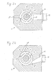
- FIGS. 2a and 2b which respectively represent a view along the sectional surface II-II through the air jet unit of FIG. 1, two variants of the advantageous design of the inlet air opening 21 and the connection opening 18 will be described below.
- the supply air opening 21 and the connection opening 18 for the vacuum source 19 are arranged in a line on opposite sides of the spindle-shaped component 17 on the annular exhaust air duct 16.
- This arrangement has the advantage that the air flowing in through the supply air opening 21 flows uniformly and symmetrically around the spindle-shaped component 17 and so can effectively prevent deposits of dirt or fiber fly in the annular exhaust duct 16.
- the supply air opening 21 and the connection opening 18 are arranged rotated in relation to FIG. 2 a about the axis of the spun yarn 1.
- the supply air opening 21 opens substantially tangentially into the annular exhaust air duct 16.
- the connection opening 18 for the vacuum source 19 extends substantially tangentially out of the annular exhaust air duct 16.
- This arrangement of the two openings 18 and 21 causes a rotating air flow to form in the annular exhaust air duct 16, or that the rotating air flow present in the swirl chamber 13 is maintained in the annular exhaust air duct 16. It may also be sufficient to arrange only one of the two openings 18 or 21 tangentially and to make the other opening, as shown in Figure 2a.
- connection opening 18 is arranged substantially in relation to the spindle-shaped component 17 with respect to the supply air opening 21, wherein - of course in the embodiment of Figure 2b - this of course the transition region 27 of the supply air opening 21 in the annular exhaust duct 16 and Transition region 28 of the connection opening 18 are relevant.
- the supply air opening 21 does not extend in a plane perpendicular to the spun yarn 1, but obliquely from the drafting 3 side facing away from the air nozzle assembly 4 opens into the annular exhaust duct 16.
- the distance of the inlet region 22 of the supply air opening 21 to the drafting system 3 can be increased, so that the intake air contains even less impurities.
- the transition region 27 from the supply air opening into the annular exhaust air duct 16 can then even protrude into the planar boundary surface of the annular exhaust air duct 16, to which the reference numeral of the end region 29 is attached in FIG.
- the supply air opening 21 to be arranged parallel to the Garnabzugskanal 14, so that the additional air flows virtually opposite to the Garnabzugscardi B on the opposite side of the connection port 18 in the annular exhaust duct 16.
Landscapes
- Engineering & Computer Science (AREA)
- Mechanical Engineering (AREA)
- Textile Engineering (AREA)
- Spinning Or Twisting Of Yarns (AREA)
Applications Claiming Priority (2)
| Application Number | Priority Date | Filing Date | Title |
|---|---|---|---|
| DE102005057113 | 2005-11-28 | ||
| DE102006047120A DE102006047120A1 (de) | 2005-11-28 | 2006-09-26 | Luftdüsenaggregat zum Herstellen eines gesponnenen Garnes |
Publications (3)
| Publication Number | Publication Date |
|---|---|
| EP1790760A2 true EP1790760A2 (fr) | 2007-05-30 |
| EP1790760A3 EP1790760A3 (fr) | 2008-09-10 |
| EP1790760B1 EP1790760B1 (fr) | 2012-10-10 |
Family
ID=37866175
Family Applications (1)
| Application Number | Title | Priority Date | Filing Date |
|---|---|---|---|
| EP20060021802 Ceased EP1790760B1 (fr) | 2005-11-28 | 2006-10-18 | Unité de buse d'air pour réaliser un fil |
Country Status (3)
| Country | Link |
|---|---|
| EP (1) | EP1790760B1 (fr) |
| CN (1) | CN1982512B (fr) |
| DE (1) | DE102006047120A1 (fr) |
Cited By (2)
| Publication number | Priority date | Publication date | Assignee | Title |
|---|---|---|---|---|
| WO2008101580A1 (fr) * | 2007-02-24 | 2008-08-28 | Oerlikon Textile Gmbh & Co. Kg | Groupe de buses à air avec dispositif pour amorcer le filage |
| CN109267191A (zh) * | 2018-11-28 | 2019-01-25 | 苏州市星京泽纤维科技有限公司 | 涡流纺纱机及其多功率可调式纺纱管 |
Families Citing this family (5)
| Publication number | Priority date | Publication date | Assignee | Title |
|---|---|---|---|---|
| DE102012101039A1 (de) * | 2012-02-09 | 2013-08-14 | Maschinenfabrik Rieter Ag | Luftspinnmaschine mit separaten Spinn- und Anspinndüsen |
| CH709466A1 (de) * | 2014-04-03 | 2015-10-15 | Rieter Ag Maschf | Spinnstelle einer Luftspinnmaschine sowie Verfahren zum Betrieb einer Luftspinnmaschine. |
| CH709465A1 (de) * | 2014-04-03 | 2015-10-15 | Rieter Ag Maschf | Luftspinnmaschine sowie Verfahren zum Betrieb einer Luftspinnmaschine. |
| DE102019205741A1 (de) * | 2019-04-18 | 2020-10-22 | Glatt Gesellschaft Mit Beschränkter Haftung | Selbstreinigende Düse |
| JP2022020895A (ja) * | 2020-07-21 | 2022-02-02 | 村田機械株式会社 | 空気紡績装置、空気紡績機、及び紡績方法 |
Family Cites Families (5)
| Publication number | Priority date | Publication date | Assignee | Title |
|---|---|---|---|---|
| JP2616428B2 (ja) * | 1994-01-25 | 1997-06-04 | 村田機械株式会社 | 紡績機の糸継ぎ方法 |
| JP2003155630A (ja) * | 2001-09-05 | 2003-05-30 | Murata Mach Ltd | 紡績装置 |
| JP2003278034A (ja) * | 2002-03-20 | 2003-10-02 | Murata Mach Ltd | 紡績装置 |
| DE10311826A1 (de) * | 2003-03-13 | 2004-09-23 | Wilhelm Stahlecker Gmbh | Vorrichtung zum Herstellen eines gesponnenen Fadens |
| JP3925533B2 (ja) * | 2004-11-05 | 2007-06-06 | 村田機械株式会社 | 紡績装置、及び繊維蓄積状態の検出方法 |
-
2006
- 2006-09-26 DE DE102006047120A patent/DE102006047120A1/de not_active Withdrawn
- 2006-10-18 EP EP20060021802 patent/EP1790760B1/fr not_active Ceased
- 2006-11-28 CN CN2006101604786A patent/CN1982512B/zh not_active Expired - Fee Related
Non-Patent Citations (1)
| Title |
|---|
| None |
Cited By (2)
| Publication number | Priority date | Publication date | Assignee | Title |
|---|---|---|---|---|
| WO2008101580A1 (fr) * | 2007-02-24 | 2008-08-28 | Oerlikon Textile Gmbh & Co. Kg | Groupe de buses à air avec dispositif pour amorcer le filage |
| CN109267191A (zh) * | 2018-11-28 | 2019-01-25 | 苏州市星京泽纤维科技有限公司 | 涡流纺纱机及其多功率可调式纺纱管 |
Also Published As
| Publication number | Publication date |
|---|---|
| EP1790760A3 (fr) | 2008-09-10 |
| CN1982512A (zh) | 2007-06-20 |
| DE102006047120A1 (de) | 2007-05-31 |
| EP1790760B1 (fr) | 2012-10-10 |
| CN1982512B (zh) | 2011-08-03 |
Similar Documents
| Publication | Publication Date | Title |
|---|---|---|
| DE102009034206A1 (de) | Bauteil für eine Luftdüsenspinnvorrichtung | |
| EP2730685B1 (fr) | Elément de formation de fil pour métier à tisser à jet d'air comprenant un insert et filière équipée de celui-ci | |
| DE3722771C1 (de) | Vorrichtung zum Zusammenfuehren eines textilen Faservlieses zu einem Faserband | |
| EP1786961A1 (fr) | Dispositif de filature a jet d'air | |
| DE2159248C3 (de) | Offenendspinnmaschine | |
| DE10311826A1 (de) | Vorrichtung zum Herstellen eines gesponnenen Fadens | |
| EP1790760B1 (fr) | Unité de buse d'air pour réaliser un fil | |
| CH674855A5 (fr) | ||
| CH681087A5 (fr) | ||
| WO2005047577A1 (fr) | Dispositif de filature a buses d'air | |
| WO2016030136A1 (fr) | Élément de filage pour une filière d'un métier à filer pneumatique, métier à filer pneumatique et procédé pour le faire fonctionner | |
| DE102005022686A1 (de) | Vorrichtung zum Herstellen eines gesponnenen Fadens | |
| DE3634792C2 (de) | Friktionsspinnvorrichtung | |
| EP2986765B1 (fr) | Banc d'étirage pour machine à tricoter | |
| CH683846A5 (de) | Vorrichtung zur Abnahme von Krempelfaserflor von der Abnahmewalze einer Krempelvorrichtung. | |
| WO2005061765A1 (fr) | Dispositif pour filer un fil a partir d'une meche de fibres discontinues | |
| CH659666A5 (de) | Einrichtung zum herstellen von buendelgarn. | |
| DE3324394C2 (de) | Vorrichtung zum Abscheiden von Verunreinigungen an Offenendspinneinheiten | |
| DE3521756C2 (fr) | ||
| DE3843655A1 (de) | Verfahren zur reinigung eins kardenbandes | |
| DE3929230A1 (de) | Einrichtung zur faserabnahme von der ausstosswalze einer offen-end-spinnmaschine | |
| EP1587974B1 (fr) | Dispositif de fabrication d'un fil file | |
| EP0289028B1 (fr) | Procédé et dispositif pour attacher un fil dans une machine de filature du type à friction | |
| DE102018111775A1 (de) | Offenendspinnvorrichtung und Drehventil für eine Offenendspinnvorrichtung | |
| DE3402368A1 (de) | Vorrichtung zum oe-friktionsspinnen |
Legal Events
| Date | Code | Title | Description |
|---|---|---|---|
| PUAI | Public reference made under article 153(3) epc to a published international application that has entered the european phase |
Free format text: ORIGINAL CODE: 0009012 |
|
| AK | Designated contracting states |
Kind code of ref document: A2 Designated state(s): AT BE BG CH CY CZ DE DK EE ES FI FR GB GR HU IE IS IT LI LT LU LV MC NL PL PT RO SE SI SK TR |
|
| AX | Request for extension of the european patent |
Extension state: AL BA HR MK YU |
|
| RIN1 | Information on inventor provided before grant (corrected) |
Inventor name: BROUWERS, WERNER CHRISTIAN MARTIN Inventor name: STRAUB, OLIVER Inventor name: WILLEMS, GERT LOUIS CLEMENT |
|
| PUAL | Search report despatched |
Free format text: ORIGINAL CODE: 0009013 |
|
| RIN1 | Information on inventor provided before grant (corrected) |
Inventor name: STRAUB, OLIVER |
|
| AK | Designated contracting states |
Kind code of ref document: A3 Designated state(s): AT BE BG CH CY CZ DE DK EE ES FI FR GB GR HU IE IS IT LI LT LU LV MC NL PL PT RO SE SI SK TR |
|
| AX | Request for extension of the european patent |
Extension state: AL BA HR MK RS |
|
| 17P | Request for examination filed |
Effective date: 20081008 |
|
| 17Q | First examination report despatched |
Effective date: 20081205 |
|
| AKX | Designation fees paid |
Designated state(s): CH CZ DE IT LI TR |
|
| RIC1 | Information provided on ipc code assigned before grant |
Ipc: D01H 5/66 20060101ALI20120222BHEP Ipc: D01H 1/115 20060101ALI20120222BHEP Ipc: D01H 4/02 20060101AFI20120222BHEP |
|
| GRAP | Despatch of communication of intention to grant a patent |
Free format text: ORIGINAL CODE: EPIDOSNIGR1 |
|
| GRAS | Grant fee paid |
Free format text: ORIGINAL CODE: EPIDOSNIGR3 |
|
| GRAA | (expected) grant |
Free format text: ORIGINAL CODE: 0009210 |
|
| AK | Designated contracting states |
Kind code of ref document: B1 Designated state(s): CH CZ DE IT LI TR |
|
| REG | Reference to a national code |
Ref country code: CH Ref legal event code: EP |
|
| REG | Reference to a national code |
Ref country code: DE Ref legal event code: R096 Ref document number: 502006012070 Country of ref document: DE Effective date: 20121206 |
|
| REG | Reference to a national code |
Ref country code: CH Ref legal event code: PL |
|
| PG25 | Lapsed in a contracting state [announced via postgrant information from national office to epo] |
Ref country code: CH Free format text: LAPSE BECAUSE OF NON-PAYMENT OF DUE FEES Effective date: 20121031 Ref country code: CZ Free format text: LAPSE BECAUSE OF FAILURE TO SUBMIT A TRANSLATION OF THE DESCRIPTION OR TO PAY THE FEE WITHIN THE PRESCRIBED TIME-LIMIT Effective date: 20121010 Ref country code: LI Free format text: LAPSE BECAUSE OF NON-PAYMENT OF DUE FEES Effective date: 20121031 |
|
| PLBE | No opposition filed within time limit |
Free format text: ORIGINAL CODE: 0009261 |
|
| STAA | Information on the status of an ep patent application or granted ep patent |
Free format text: STATUS: NO OPPOSITION FILED WITHIN TIME LIMIT |
|
| PG25 | Lapsed in a contracting state [announced via postgrant information from national office to epo] |
Ref country code: IT Free format text: LAPSE BECAUSE OF FAILURE TO SUBMIT A TRANSLATION OF THE DESCRIPTION OR TO PAY THE FEE WITHIN THE PRESCRIBED TIME-LIMIT Effective date: 20121010 |
|
| 26N | No opposition filed |
Effective date: 20130711 |
|
| REG | Reference to a national code |
Ref country code: DE Ref legal event code: R097 Ref document number: 502006012070 Country of ref document: DE Effective date: 20130711 |
|
| PGFP | Annual fee paid to national office [announced via postgrant information from national office to epo] |
Ref country code: TR Payment date: 20161011 Year of fee payment: 11 |
|
| PG25 | Lapsed in a contracting state [announced via postgrant information from national office to epo] |
Ref country code: TR Free format text: LAPSE BECAUSE OF NON-PAYMENT OF DUE FEES Effective date: 20171018 |
|
| PGFP | Annual fee paid to national office [announced via postgrant information from national office to epo] |
Ref country code: DE Payment date: 20221117 Year of fee payment: 17 |
|
| P01 | Opt-out of the competence of the unified patent court (upc) registered |
Effective date: 20230329 |
|
| REG | Reference to a national code |
Ref country code: DE Ref legal event code: R119 Ref document number: 502006012070 Country of ref document: DE |
|
| PG25 | Lapsed in a contracting state [announced via postgrant information from national office to epo] |
Ref country code: DE Free format text: LAPSE BECAUSE OF NON-PAYMENT OF DUE FEES Effective date: 20240501 |