EP1790773A2 - Encoffrage de chaussée - Google Patents
Encoffrage de chaussée Download PDFInfo
- Publication number
- EP1790773A2 EP1790773A2 EP06024542A EP06024542A EP1790773A2 EP 1790773 A2 EP1790773 A2 EP 1790773A2 EP 06024542 A EP06024542 A EP 06024542A EP 06024542 A EP06024542 A EP 06024542A EP 1790773 A2 EP1790773 A2 EP 1790773A2
- Authority
- EP
- European Patent Office
- Prior art keywords
- window
- housing according
- ceiling
- carriageway
- windows
- Prior art date
- Legal status (The legal status is an assumption and is not a legal conclusion. Google has not performed a legal analysis and makes no representation as to the accuracy of the status listed.)
- Withdrawn
Links
Images



Classifications
-
- E—FIXED CONSTRUCTIONS
- E01—CONSTRUCTION OF ROADS, RAILWAYS, OR BRIDGES
- E01F—ADDITIONAL WORK, SUCH AS EQUIPPING ROADS OR THE CONSTRUCTION OF PLATFORMS, HELICOPTER LANDING STAGES, SIGNS, SNOW FENCES, OR THE LIKE
- E01F8/00—Arrangements for absorbing or reflecting air-transmitted noise from road or railway traffic
- E01F8/0005—Arrangements for absorbing or reflecting air-transmitted noise from road or railway traffic used in a wall type arrangement
- E01F8/0047—Arrangements for absorbing or reflecting air-transmitted noise from road or railway traffic used in a wall type arrangement with open cavities, e.g. for covering sunken roads
-
- E—FIXED CONSTRUCTIONS
- E01—CONSTRUCTION OF ROADS, RAILWAYS, OR BRIDGES
- E01C—CONSTRUCTION OF, OR SURFACES FOR, ROADS, SPORTS GROUNDS, OR THE LIKE; MACHINES OR AUXILIARY TOOLS FOR CONSTRUCTION OR REPAIR
- E01C1/00—Design or layout of roads, e.g. for noise abatement, for gas absorption
- E01C1/005—Means permanently installed along the road for removing or neutralising exhaust gases
Definitions
- the invention relates to an enclosure for a roadway, with a roadway spanning ceiling and side panels on both sides, all together define a roadway containing the roadway, at least a first of the side panels with their side facing away from the road adjacent to an outdoor area, and with Means for supplying supply air from the outside area into the roadway space and for discharging exhaust air from the roadway space to the outside area.
- Roadways in the context of this invention include single or multi-lane roads, including any side strips and banquets, as well as railway lines, each with oncoming traffic.
- An enclosure of the type mentioned is from the EP 0 567 040 A1 known.
- the housing described there has a side panel which has at least one supply air opening on a region closer to the roadway and also at least one exhaust air opening on a region remote from the roadway.
- Such enclosures must comply with the applicable tunnel regulations for ventilation and also for the smoke evacuation in case of fire. Because of this, fans are necessary to guarantee the required air exchange. This is associated with a considerable technical effort and high costs.
- the object of the invention is to improve a generic housing so that their ventilation takes place in a simpler manner.
- this object is achieved in a housing of the type mentioned above in that the ceiling has elongated cavities extending transversely to the roadway and one end of the roadway space is open and the other end is open to the outside, and in that the first side panel has window elements that can be opened and a device for automatically opening the window elements that responds to a predetermined signal.
- the measures according to the invention bring about the legally required air exchange in the enclosure during normal operation and in dust operation and also in an emergency.
- the enclosure In normal traffic, i. above about 25 km / h, the enclosure "breathes" automatically with closed window elements. Characterized in that elongated, extending transversely to the roadway cavities are arranged in the ceiling, which open on the one hand to the carriageway space and on the other hand to the outside area, these cavities serve as airlock. Through them, the exhaust air is forced out in front of the vehicles in normal driving due to the piston action of the vehicles by the pressure and sucked fresh air behind the vehicles in the same way by the suction.
- Such a design of the ceiling is associated with no or no significant additional costs, since known components, eg. B. hollow floorboards, can be used. Noise emission is not present, because no traffic noise penetrates into the exterior area because of the length of the blow-out distance.
- it is achieved by the inventive design of the ceiling that not at the end of the enclosure, the entire concentrated exhaust air is blown out, but that the blowout over the entire length as distributed on the open track.
- one end of each cavity is located on one side of the roadway and the other end of each cavity on the other side of the roadway.
- the blow-out is formed as long as possible.
- the structural design of the ceiling is simplified by avoiding impurities.
- the ceiling is formed as a hollow floorboard.
- no additional costs are incurred for the formation of the elongate cavities, since the cavities or channels already present in the hollow floorboard can be used for supplying the supply air and for discharging the exhaust air.
- the window elements form at least 20% of the area of the first side panel. This ensures ventilation with open window elements, which equals the conditions on the free route.
- the window elements may also form a smaller area of the first side panel. It is essential, however, that the ventilation with open windows is so large that the enclosure no longer falls under the tunnel regulations.
- the windows are designed as sliding windows.
- the space requirement is kept extremely low laterally outside the enclosure to open the window.
- the sliding windows are horizontally displaceable. As a result, the entire height of the window opening for ventilation is available. The formation of a chimney effect is thus favored.
- the sliding windows run with convex guide wheels in guide rails and are height adjustable. Deviations from the vertical mounting of the guide rail and inaccuracies in assembly and production of the substructure of the guide rails can be compensated.
- the guide rails are designed as downwardly open U-profiles.
- the window elements are formed as a rotating window. Turn windows allow the entire window area to be opened, providing maximum ventilation.
- the rotary windows are preferably rotatable about a central, vertical axis of rotation. As a result of this measure, the free space required for opening the rotary windows is kept small next to the side paneling.
- the rotary windows are rotatable by at least 170 °.
- the window outer sides can be turned inwards and cleaned in a simple manner by a washing vehicle passing on the roadway.
- the first side panel precast concrete in the form of an inverted T on the vertical portion (pillar) rests the ceiling and on the horizontal portion (wall), the window elements are attached.
- T-shape unit pillars / walls creates a strip foundation, which can be easily fixed in the pavement. This saves considerable costs and assembly time.
- the horizontal sections advantageously have a bottom for resting on a substrate and protrude from the bottom of bolts, with which the precast concrete element is fixable in the ground.
- a T-shaped precast concrete part can be fixed in this way by only two bolts in the pavement.
- the adjacent horizontal portions of adjacent precast concrete parts are connected by a tongue and groove joint.
- thrust forces arising, for example, from a collision of vehicles can be accommodated in a cost-effective manner.
- the vertical height of the horizontal sections is substantially equal to the guardrail height, d. H. the vertical height of the horizontal sections is approximately 0.925 m.
- the vehicle occupants can thus overcome the horizontal sections of the precast concrete elements with open windows in order to reach the outside.
- the horizontal sections of the precast concrete parts therefore do not constitute a major obstacle to the guardrail over the open road.
- a sliding window and the other half length a fixed part on which the sliding window is completelylesschiebbar. This will be minimal lateral space requirement achieved a maximum open window area.
- the sliding window and the fixed part are advantageously formed as window panes, which are fastened on one of their flat sides in each case on a frame, wherein the one frame on the carriageway facing flat side and the other frame is fixed on the outer side facing the flat side. So are the windows of the fixed and the movable part with their smooth sides facing each other with open sliding windows. A risk of accident in that someone with one hand or with one leg gets stuck on the sliding window and is pulled into the gap between sliding window and fixed part is avoided.
- rotary windows are arranged over the entire length between adjacent vertical sections, which in each case extend over the entire height between the horizontal section and the ceiling and whose width is approximately equal to the thickness of the horizontal section.
- window elements are used in the entire opening area of the first side panel, which can be opened, so that with the windows open, this entire opening area is actually 100% open. Since the width of the individual pivoting windows does not exceed the thickness of the horizontal section, no additional space for opening the windows must be kept free laterally next to the side covering.
- all the windows of the first side panel are formed of a material that becomes so soft at a predetermined temperature that the window panes collapse. In case of fire, this would make the side cover in any case, ie without mechanical or manual assistance, be open over its entire length. In particular, for the case of fire is thus ensured that the capacity for the escape of hot air or hot Smoke is extremely large and in a size range that can not be achieved with fans close to.
- an enclosure according to the invention has a measuring device for measuring predefined air characteristics in the carriageway space and a signaling device which is connected to the measuring device and to the device for automatically opening the window elements and to which the measured values are fed and which, when the measured values reach predetermined limits, generates the predetermined signal and the means for automatically opening the window elements zumony.
- the measuring device for measuring the visibility turbidity and / or for measuring the CO 2 content can be set up and / or have at least one fire alarm cable. The security of the enclosure is thereby considerably increased.
- each window element is associated with an accumulator, which supplies the device for automatically opening the window elements in case of failure of the mains power.
- an enclosure according to the invention has a device for manually opening the window elements.
- opening of the window elements is made possible even in total failure of the power supply.
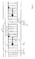
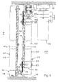
- the exemplary embodiments of enclosures 1 according to the invention for a carriageway 2 have a ceiling 3, a first side panel 4 on one side of the roadway and a second side panel 5 opposite the first side panel 4 on the other side of the roadway.
- the ceiling 3 spans the entire roadway 2 and rests on the side panels 4, 5.
- elongated cavities 6 are formed, which extend across the entire lane 2 from a longitudinal edge 7 of the ceiling 3 to the other longitudinal edge 8 and there at one end in the carriageway space 9 and at its other end in the outer area 10th lead.
- the two side panels 4, 5 and the ceiling 3 limit the roadway 2 containing the carriageway space 9, which in turn contains a predetermined clearance space 11.
- a predetermined clearance space 11 In the embodiment shown in Figures 1 and 2 is on the side facing away from the lane 2 of the ceiling 3 and the first side panel 4 as an outdoor area 10, the free environment or natural atmosphere.
- the second side panel 5 forms in this case a middle wall between the two housings 1, 1 'and will be referred to in the following.
- the roadway 2 is a conventional single or multi-lane road cross-section with side banquets, in which an extinguishing water pipe 12 and a drainage channel 13 are arranged.
- the surfaces of the road have a bank.
- the ceiling 3 has a bank.
- the ceiling 3 is formed in the illustrated embodiment as Hohldielendecke (Fig. 3) and is above beams 14, 15 on the two side panels 4, 5 on.
- Each hollow plank 16 has four cavities 6.
- the side panels 4, 5 have pillars 17, 18, which are arranged at a predetermined distance from each other along the roadway 2. On the pillars 17, 18 are parallel to the roadway 2 extending beams 14, 15, on which in turn the ceiling 3 rests.
- the height of the first side panel 4 preferably corresponds to the guardrail height, ie the upper edge is 0.925 m above the ground.
- the opening 21, 22 delimited by two adjacent pillars 17 or 18 and by the beam 14 or 15 and the base wall 19 or 20 will hereinafter be referred to as a compartment.
- each window elements 23 are arranged, which can be opened.
- the base wall 20 can here as Ortbetonwand with a height of z. B. 2.3 m on a strip foundation 25 may be formed.
- the outer longitudinal edge 7 may be covered with an attic 26, which has a predetermined distance to the mouth of the cavities 6a, to allow unimpeded outflow of the exhaust air in the outer region 10 opening ends of these cavities 6a in the outer longitudinal edge 7 of the ceiling 27 or to ensure inflow of the supply air 28. This distance can be about 20 cm.
- the remaining hollow floorboards 16 are guided to the attic 26 and give the corresponding static strength.
- This channel 29 is parallel to the roadway 2 and is above lateral openings 30, in the present Case seven openings 30, with the carriageway space 9 in fluid communication.
- the sound waves are thus redirected three times - when entering the carriageway space 9 in the beam 15 on the second Side panel 5, the transition from the joist 15 in the ceiling 3 and the outlet between the ceiling 3 and Attic 26 - whereby the possibility of escape of traffic noise on the cavities 6a is largely prevented.
- the channel 29 is longer by a predetermined amount than the width of a hollow plank 16, so that the position of the hollow plank 16, which has provided for the ventilation and venting cavities 6a, relative to the channel 29 may be variable. In this way, the grid dimension for the laying of the hollow floorboards 16 can be selected largely independently of the position of the channel 29.
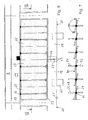
- a sliding window 40 and a fixed part 41 or window are respectively installed in the compartments 21, which are arranged side by side in the direction of the road and each form half of the compartment 21.
- the sliding window 40 can be moved to open completely next to the fixed window 41, so that then 50% of the compartment 21 are open.
- the pillars 17 are fixed in individual quiver foundations 42, and the base wall 19 is formed as Betongleitwand on a strip foundation 42a.
- the window panes 43a, 43 of the fixed window 41 and the sliding window 40 are each attached to frame racks 45, 44, wherein in the embodiment shown in Figure 5 the frame 45 of the fixed window 41 on the roadway side and the frame frame 44 of the sliding window 40 is arranged on the outer region 10 facing side.
- the smooth window pane sides 47, 46 of the fixed window 41 and the sliding window 40 face each other. This reduces the risk that when opening the sliding window 40, a person z. B. stuck with her hand or her leg to the windows 40, 41 and 40 is pulled into the gap between the fixed window 41 and sliding window 40 when opening the sliding window 40.
- the frame 45 of the fixed window 41 has a peripheral frame 48 and vertical struts 49 and is bolted to the base wall 19.
- the window pane 43a in turn is bolted to the frame 45.
- the frame 44 of the sliding window 40 also has a peripheral frame 50 and vertical struts 51.
- the frame 44 is guided on the one hand in an upper guide rail 52, which is bolted to the beam 14, and on the other hand guided in a lower guide rail 53, which is bolted to the base wall 19 together with the frame 45 of the fixed window 41.
- the guide rails 52, 53 are formed as downwardly open U-profiles.
- the frame 45 of the fixed window 41 is welded to the upper guide rail 52 of the sliding window 40, so that a separate screw in the beam 14 is avoided.
- plastic sheets 54 are attached, which seal the slits between the window pane 43 and the guide rails 52, 53 and also between the window pane 43 and the pillar 17 on the one hand and the fixed window 41 on the other hand noise-insulating.
- guide wheels 55, 56 are fixed, which run in the guide rails 52, 53.
- the running in the lower guide rail 53 guide wheel 56 has a spherical shape to compensate for inaccuracies in the assembly of the guide rail 53.
- the attachment of this crowned guide wheel 56 on the frame frame 44 is adjustable in height to compensate for assembly and production tolerances can.
- the attachment is by screw 57, wherein the holder of the lower guide wheel 56 is secured against rotation with a second screw.
- the sliding windows 40 may be provided with a Wasserabstreifer that cleans the sliding windows 40 when opening and closing.
- the fixed window 41 and the sliding window 40 can be factory pre-assembled. This saves considerable costs and installation time on the construction site.
- Each sliding window 40 has a drive unit 58 with integrated accumulator and hand lock.
- the accumulator ensures sufficient power to open the sliding window 40 even in case of power failure.
- each sliding window 40 on its side facing the outside area on a device for manual opening of the sliding window 40.
- the drive units 58 are connected to a signaling device (not shown) and configured to completely open the associated sliding window 40 upon receipt of a predetermined signal.
- the signaling device in turn is connected to a (not shown) measuring device which is arranged in the housing 1 and adapted to measure the visibility and / or the CO 2 content and / or has a fire alarm cable.
- the measuring device sends the measured values to the signal device Furthermore, if the measured values reach predetermined limits, the predetermined signal is generated and forwarded to the drive units 58 of the sliding windows 40, whereupon the drive units 58 move the sliding windows 40 into the open position.
- the window panes 43, 43a may be formed of a material which softens and collapses at a predetermined temperature, so that the entire compartment surface is then available for the smoke evacuation in the event of a fire. It is conceivable, for example, that the window panes 43, 43a are made of polycarbonate and collapse at a temperature of about 200 ° C.
- the open intake duct 59 with suction port wall 19 can be converted as a strip foundation and shed massive with the pillar 17.
- the pressure of the pillar is optimally distributed over the entire base area of the pillar and base wall.
- a pillar 17, together with the two base wall sections 19 adjoining it, each extending over half of the adjacent compartment 21, is designed as precast concrete element 60 in the form of an inverted T.
- a bolt 62 is inserted or formed, the diameter of which is preferably 70 cm.
- the bolts 62 are inserted into holes drilled in the ground to fix the side panel 4 in the ground and forward shear and tipping forces.
- a truck-direct impact and a Kippanprall can be collected easily.
- the tearing of the road surface for the much larger individual foundations is avoided.
- the adjacent base wall portions 19 of adjacent precast concrete elements are interlocked by a tongue and groove joint 63 to aid in transverse stability.
- the mutually facing end faces 64 of the base wall portions 19 are accordingly formed as a vertical groove and spring parts.
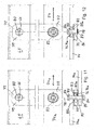
- each compartment pivot windows 65 are installed, in the illustrated embodiment six pivot windows 65. They each have a central vertical axis of rotation 66 to which the pivot window 65 from a closed position 67 by 90 ° in a opened position 68 is rotatable. In this embodiment, 100% of the surface of the compartment 21 are therefore open when the rotation windows 65 are opened (FIG. 7).
- the windows 65 can be further rotated, for example by 170 ° or up to 180 °.
- the window outer sides 70 are turned inwards on the road side and can be easily cleaned, for example, by a passing washing vehicle.
- the two sashes 71, 72 of each rotation window 65 may be fixed to the rotation axis 66 so as to be aligned with each other or offset from each other by a predetermined amount across their window surface. In the latter case, the vertical length of the window sash 71, 72 could be greater than the clear height of the window frame 73.
- the two sashes 71, 72 of a rotating window 65 then lie in the closed state on opposite sides of the window frame 73 laterally to this.
- the pivot windows 65 are by a drive unit per compartment 21 z. B. driven by racks.
- the pivoting windows 65 are rotated by means of push rods 74, which are connected via release levers 75 to the axes of rotation 66 of the pivoting windows 65, respectively.
- the push rod 74 is formed as a chain of link rods 74a, which are also hingedly connected at their joints or points 76 with one end 77 of a release lever 75.
- the corresponding hinge or push rods 74a and the associated release lever 75 are each rotatable about the same axis of rotation 78, said axis of rotation 78 is parallel to the axis of rotation 66 of the rotary window 65.
- the release lever 75 is rigid or rigid. With the pivot window 65 of the release lever 75 is connected at its second end 79 via a pivot pin 80 to which both the release lever 75 and the pivot window 65 is rotatably attached.
- the left outer hinge point - is connected via a further push rod 74a with a drive motor 81, with which the push rods 74a are slidable in their longitudinal direction.
- the articulation points 77 of the release lever 75 are displaced on the push rods 74a, which in turn the release lever 75 about its second ends 79, which are rotatably connected to the rotation axis 66 and the pivot pin 80 of the respective rotation window 65, pivoted and so the pivot window 65 are rotated about its axis of rotation 66 in a desired open position or in the closed position.
- the disengagement lever 75 can be arranged in the articulation point 76, 76a between the two articulated rods 74a, that is to say in the embodiment shown in FIG. 11 between an upper articulation rod 74a which is connected to the left adjacent disengagement lever 75, and a lower push rod 74a connected to the right adjacent release lever 75.
- the two hinge rods 74a and the release lever 75 are traversed by a hinge pin 82 which forms the axis of rotation 78.
- a ball bearing 83 is pressed, which surrounds the hinge pin 82.
- the hinge pin 82 has at its two ends in each case a self-locking nut 84 which rests on a respective washer 85 on the upper and the lower push rod 74a. Between the push rods 74a and the release lever 75 also washer 85a are also arranged.
- the push rod 74 is not formed as a chain of link rods, but as a continuous push rod on which the release lever 75 are hinged.
- the ball bearing 83 is pressed into the push rod 74 at each articulation point 76, 76 a.
- a stud bolt 86 passes through the Push rod 74 and the ball bearing 83 and the release lever 75.
- the stud bolt 86 is rotatably connected to the release lever 75.
- the stud bolt 86 has a self-locking nut 84 which rests on the ball bearing 83 via a washer 85. Between the push rod 74 and release lever 75 is also a washer 85 a arranged.
- the drive of the pivot windows 65 is automatically or manually operable in a similar manner, as already described in connection with the execution of the window elements as a sliding window 40.
- the design of the window elements 23 is not limited. For example, the use of folding windows is not excluded.
Landscapes
- Engineering & Computer Science (AREA)
- Architecture (AREA)
- Civil Engineering (AREA)
- Structural Engineering (AREA)
- Specific Sealing Or Ventilating Devices For Doors And Windows (AREA)
Applications Claiming Priority (1)
| Application Number | Priority Date | Filing Date | Title |
|---|---|---|---|
| DE200510056251 DE102005056251B3 (de) | 2005-11-25 | 2005-11-25 | Fahrbahneinhausung |
Publications (2)
| Publication Number | Publication Date |
|---|---|
| EP1790773A2 true EP1790773A2 (fr) | 2007-05-30 |
| EP1790773A3 EP1790773A3 (fr) | 2007-08-15 |
Family
ID=37776065
Family Applications (1)
| Application Number | Title | Priority Date | Filing Date |
|---|---|---|---|
| EP06024542A Withdrawn EP1790773A3 (fr) | 2005-11-25 | 2006-11-27 | Encoffrage de chaussée |
Country Status (2)
| Country | Link |
|---|---|
| EP (1) | EP1790773A3 (fr) |
| DE (1) | DE102005056251B3 (fr) |
Cited By (1)
| Publication number | Priority date | Publication date | Assignee | Title |
|---|---|---|---|---|
| CN110295913A (zh) * | 2019-08-05 | 2019-10-01 | 中信国安建工集团有限公司 | 一种隧道爆破开挖系统及施工方法 |
Family Cites Families (6)
| Publication number | Priority date | Publication date | Assignee | Title |
|---|---|---|---|---|
| DE7610504U1 (fr) * | Colberg, Norbert, 3150 Peine | |||
| DE2723780A1 (de) * | 1977-05-26 | 1978-12-14 | Baur Baur | Be- und entlueftung von hochstrassen-tunneln |
| DE2909473A1 (de) * | 1979-03-10 | 1980-09-11 | Zueblin Ag | Laermschutztunnel mit querlueftung |
| DE3700315A1 (de) * | 1987-01-05 | 1988-07-14 | Strobach Elektromeister Gmbh | Grossflaechenwaermetauscher |
| DE59303707D1 (de) * | 1992-04-22 | 1996-10-17 | Witting Gerhard | Seitenverkleidung für ein Strassenbauwerk |
| AT500256A1 (de) * | 2003-04-25 | 2005-11-15 | Emil Johannes D Wieser-Linhart | Einrichtung zur reduzierung der lärm- und schadstoffbelastung entlang eines verkehrsweges |
-
2005
- 2005-11-25 DE DE200510056251 patent/DE102005056251B3/de not_active Expired - Fee Related
-
2006
- 2006-11-27 EP EP06024542A patent/EP1790773A3/fr not_active Withdrawn
Cited By (2)
| Publication number | Priority date | Publication date | Assignee | Title |
|---|---|---|---|---|
| CN110295913A (zh) * | 2019-08-05 | 2019-10-01 | 中信国安建工集团有限公司 | 一种隧道爆破开挖系统及施工方法 |
| CN110295913B (zh) * | 2019-08-05 | 2024-05-07 | 中信国安建工集团有限公司 | 一种隧道爆破开挖系统及施工方法 |
Also Published As
| Publication number | Publication date |
|---|---|
| DE102005056251B3 (de) | 2007-03-22 |
| EP1790773A3 (fr) | 2007-08-15 |
Similar Documents
| Publication | Publication Date | Title |
|---|---|---|
| DE69615216T2 (de) | Entwässerungssystem für horizontal gleitende verschliesselemente | |
| EP2907921B1 (fr) | Système de barrière | |
| EP2049734B1 (fr) | Installation routière | |
| CH638580A5 (de) | Fahrbahnsperre fuer fahrzeuge. | |
| EP0567040A1 (fr) | Caches latéraux pour ouvrage routière | |
| DE3422151A1 (de) | Schallschutzfenster | |
| EP1632607B1 (fr) | panneau antibruit avec filtre | |
| EP0892118A1 (fr) | Elément de construction pour l' isolation thermique | |
| CH678737A5 (fr) | ||
| DE102005056251B3 (de) | Fahrbahneinhausung | |
| DE69519176T2 (de) | Geräuschunterdrückungsvorrichtung für Schienenwege | |
| EP0730068B1 (fr) | Lucarne | |
| WO2023057507A2 (fr) | Système photovoltaïque pour voies de circulation | |
| DE4023494C2 (de) | Lüftungsvorrichtung | |
| EP3318436A1 (fr) | Système de toit de véhicule automobile | |
| DE10210989A1 (de) | Lärmschutzwand für Verkehrswege und Modul hierfür | |
| DE102017118275B4 (de) | Torvorrichtung und diese enthaltende Toranordnung | |
| DE102016115424B4 (de) | Fenster | |
| EP2692949B1 (fr) | Paroi de protection phonique basse à côté d'une voie ferrée et élément de paroi de protection phonique pour la formation d'une telle paroi de protection phonique | |
| AT522398B1 (de) | Klappschott | |
| DE202013003966U1 (de) | Veranstaltungspavillon und Pavilloelement zum Aufbau eines solchen Veranstaltungspavillons | |
| AT7753U1 (de) | Schienenschallschutzelement | |
| DE20219637U1 (de) | Lärmschutzwand | |
| DE4419056A1 (de) | Gebäude mit geschlossener Galerie | |
| EP3318710B1 (fr) | Système de seuil de porte |
Legal Events
| Date | Code | Title | Description |
|---|---|---|---|
| PUAI | Public reference made under article 153(3) epc to a published international application that has entered the european phase |
Free format text: ORIGINAL CODE: 0009012 |
|
| AK | Designated contracting states |
Kind code of ref document: A2 Designated state(s): AT BE BG CH CY CZ DE DK EE ES FI FR GB GR HU IE IS IT LI LT LU LV MC NL PL PT RO SE SI SK TR |
|
| AX | Request for extension of the european patent |
Extension state: AL BA HR MK YU |
|
| PUAL | Search report despatched |
Free format text: ORIGINAL CODE: 0009013 |
|
| AK | Designated contracting states |
Kind code of ref document: A3 Designated state(s): AT BE BG CH CY CZ DE DK EE ES FI FR GB GR HU IE IS IT LI LT LU LV MC NL PL PT RO SE SI SK TR |
|
| AX | Request for extension of the european patent |
Extension state: AL BA HR MK YU |
|
| RIC1 | Information provided on ipc code assigned before grant |
Ipc: E01F 8/00 20060101ALN20070330BHEP Ipc: E21F 1/00 20060101ALI20070710BHEP Ipc: E01C 1/00 20060101AFI20070330BHEP |
|
| 17P | Request for examination filed |
Effective date: 20080214 |
|
| AKX | Designation fees paid |
Designated state(s): AT BE BG CH CY CZ DE DK EE ES FI FR GB GR HU IE IS IT LI LT LU LV MC NL PL PT RO SE SI SK TR |
|
| 17Q | First examination report despatched |
Effective date: 20080513 |
|
| STAA | Information on the status of an ep patent application or granted ep patent |
Free format text: STATUS: THE APPLICATION IS DEEMED TO BE WITHDRAWN |
|
| 18D | Application deemed to be withdrawn |
Effective date: 20090407 |