EP1790783A2 - Toilette avec distributeur d'eau de chasse - Google Patents
Toilette avec distributeur d'eau de chasse Download PDFInfo
- Publication number
- EP1790783A2 EP1790783A2 EP06018359A EP06018359A EP1790783A2 EP 1790783 A2 EP1790783 A2 EP 1790783A2 EP 06018359 A EP06018359 A EP 06018359A EP 06018359 A EP06018359 A EP 06018359A EP 1790783 A2 EP1790783 A2 EP 1790783A2
- Authority
- EP
- European Patent Office
- Prior art keywords
- diverter
- fluid
- open
- valve
- flush valve
- Prior art date
- Legal status (The legal status is an assumption and is not a legal conclusion. Google has not performed a legal analysis and makes no representation as to the accuracy of the status listed.)
- Withdrawn
Links
Images


Classifications
-
- E—FIXED CONSTRUCTIONS
- E03—WATER SUPPLY; SEWERAGE
- E03D—WATER-CLOSETS OR URINALS WITH FLUSHING DEVICES; FLUSHING VALVES THEREFOR
- E03D3/00—Flushing devices operated by pressure of the water supply system flushing valves not connected to the water-supply main, also if air is blown in the water seal for a quick flushing
-
- E—FIXED CONSTRUCTIONS
- E03—WATER SUPPLY; SEWERAGE
- E03D—WATER-CLOSETS OR URINALS WITH FLUSHING DEVICES; FLUSHING VALVES THEREFOR
- E03D5/00—Special constructions of flushing devices, e.g. closed flushing system
- E03D5/012—Special constructions of flushing devices, e.g. closed flushing system combined with movable closure elements in the bowl outlet
-
- E—FIXED CONSTRUCTIONS
- E03—WATER SUPPLY; SEWERAGE
- E03D—WATER-CLOSETS OR URINALS WITH FLUSHING DEVICES; FLUSHING VALVES THEREFOR
- E03D5/00—Special constructions of flushing devices, e.g. closed flushing system
- E03D5/02—Special constructions of flushing devices, e.g. closed flushing system operated mechanically or hydraulically (or pneumatically) also details such as push buttons, levers and pull-card therefor
- E03D5/08—Special constructions of flushing devices, e.g. closed flushing system operated mechanically or hydraulically (or pneumatically) also details such as push buttons, levers and pull-card therefor directly by the foot combined with devices for opening or closing shutters in the bowl outlet and/or with devices for raising or lowering seat and cover and/or for swiveling the bowl
-
- E—FIXED CONSTRUCTIONS
- E03—WATER SUPPLY; SEWERAGE
- E03D—WATER-CLOSETS OR URINALS WITH FLUSHING DEVICES; FLUSHING VALVES THEREFOR
- E03D9/00—Sanitary or other accessories for lavatories ; Devices for cleaning or disinfecting the toilet room or the toilet bowl; Devices for eliminating smells
-
- E—FIXED CONSTRUCTIONS
- E03—WATER SUPPLY; SEWERAGE
- E03D—WATER-CLOSETS OR URINALS WITH FLUSHING DEVICES; FLUSHING VALVES THEREFOR
- E03D9/00—Sanitary or other accessories for lavatories ; Devices for cleaning or disinfecting the toilet room or the toilet bowl; Devices for eliminating smells
- E03D9/08—Devices in the bowl producing upwardly-directed sprays; Modifications of the bowl for use with such devices ; Bidets; Combinations of bowls with urinals or bidets; Hot-air or other devices mounted in or on the bowl, urinal or bidet for cleaning or disinfecting
- E03D9/085—Hand-held spray heads for bidet use or for cleaning the bowl
-
- E—FIXED CONSTRUCTIONS
- E03—WATER SUPPLY; SEWERAGE
- E03D—WATER-CLOSETS OR URINALS WITH FLUSHING DEVICES; FLUSHING VALVES THEREFOR
- E03D2201/00—Details and methods of use for water closets and urinals not otherwise provided for
- E03D2201/40—Devices for distribution of flush water inside the bowl
Definitions
- the present invention relates generally to a fluid diverter device, and more particularly, to a toilet apparatus including a vacuum breaker diverter.
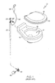
- FIG. 1 illustrates a partial exploded view of portions of a conventional toilet 10 including a conventional hand spray nozzle 28.
- the conventional toilet 10 includes a main body portion 12 with a toilet bowl 14 and a flush rim 16 for dispensing water into the toilet bowl 14.
- a foot pedal 20 can be pressed to open a flush valve 18 and thereby dispense water through the flush rim 16 and into the toilet bowl 14.
- the conventional toilet 10 also includes a lid 13 and seat 15 shown exploded from the main body portion 12.
- FIGS. 1, 2A and 2B illustrate a conventional vacuum breaker diverter 24 of the conventional toilet 10, in somewhat simplified, schematic form.
- the conventional vacuum breaker diverter 24 operates according to known principles to prevent an undesirable reverse fluid flow due to an underpressure condition that might develop after a flushing operation.
- the conventional vacuum breaker diverter 24 includes a first vertical tube 32 with a first opening 34.
- An upper end of a vertical pipe 22 can be placed in fluid communication with the first opening 34 of the vertical tube 32 while a lower end of the vertical pipe 22 can be placed in fluid communication with the flush valve 18.
- the conventional vacuum breaker diverter 24 also has a second vertical tube 36 in fluid communication with a second opening 38 and a third opening 40.
- a horizontal tube 26 includes the second opening 38 for supplying the flush rim 16 with water.
- the third opening 40 is configured for connecting to a flexible hose 30 for supplying water to the hand spray nozzle 28.
- an operator can press a foot pedal 20 to open a flush valve 18. Once the flush valve 18 is opened, water flows up through the vertical pipe 22, through the vacuum breaker diverter 24 and out the flush rim 16 into the toilet bowl 14. Additionally, while the foot pedal 20 is pressed, an operator can also use the hand spray nozzle 28 to assist in cleaning the toilet bowl 14. Using the hand spray nozzle 28 can help clean the toilet bowl 14 with less water when compared to cleaning operations only using the flush rim 16.
- the conventional toilet 10 has proven effective to provide convenient cleaning of the toilet bowl with a reduced amount of water.
- the conventional vacuum breaker diverter 24 allows a significant portion of the water to be dispensed by the flush rim 16 while using the hand spray nozzle 28.
- the conventional vacuum breaker diverter 24 is known to divide a water stream from a flush valve 18 such that slightly less than 41 % of the water stream is dispensed by the hand spray nozzle 28 while the remaining portion of the water stream is dispensed by the flush rim 16. Therefore, more water may be required to perform the cleaning operation since a significant portion of the water continues to be dispensed by the flush rim 16 when using the hand spray nozzle 28.
- water may be dispensed at a lower velocity from the hand spray nozzle 28 if a substantial amount of water continues to be dispensed by the flush rim 16 when using the hand spray nozzle 28.
- a toilet apparatus adapted to be placed in fluid communication with a fluid source comprising a bowl, a fluid dispenser adapted to dispense a fluid into the bowl, and a flush valve adapted to be placed in fluid communication with a fluid source.
- a spraying apparatus is further provided including a spray valve biased to a closed position, wherein the spraying apparatus is adapted to dispense a fluid upon opening of the spray valve.
- a vacuum breaker diverter is further provided in fluid communication with the flush valve, the fluid dispenser and the spraying apparatus. The vacuum breaker diverter is adapted to direct substantially all of a fluid stream from the flush valve to the fluid dispenser while the flush valve is open and the spray valve is closed. The vacuum breaker diverter is further adapted to direct greater than 41% of a fluid stream from the flush valve to the spraying apparatus while the flush valve is open and the spray valve is open.
- a toilet apparatus adapted to be placed in fluid communication with a fluid source comprising a bowl, a fluid dispenser adapted to dispense a fluid into the bowl, and a flush valve adapted to be placed in fluid communication with a fluid source.
- a spraying apparatus is further provided including a spray valve biased to a closed position, wherein the spraying apparatus is adapted to dispense a fluid upon opening of the spray valve.
- a vacuum breaker diverter is further provided including a diverter chamber and a diverter device movable within the diverter chamber between a first position and a second position. The diverter device is adapted to move to the first position when the flush valve is open and the spray valve is closed. The diverter device is also adapted to move to the second position when the flush valve is open and the spray valve is open.
- a toilet apparatus adapted to be placed in fluid communication with a fluid source comprising a bowl, a fluid dispenser adapted to dispense a fluid into the bowl, and a flush valve adapted to be placed in fluid communication with a fluid source.
- a spraying apparatus is further provided including a spray valve biased to a closed position, wherein the spraying apparatus is adapted to dispense a fluid upon opening of the spray valve.
- a vacuum breaker diverter including a diverter chamber and a diverter piston configured to reciprocate within the diverter chamber between a first position to direct substantially all of a fluid stream from the flush valve to the fluid dispenser and a second position to direct greater than 41 % of a fluid stream from the flush valve to the spraying apparatus.
- the diverter piston is adapted to move to the first position when the flush valve is open and the spray valve is closed.
- the diverter piston is also adapted to move to the second position when the flush valve is open and the spray valve is open.
- FIG. 1 is a partial exploded view of portions of a conventional toilet
- FIG. 2A is a front view of a conventional vacuum breaker of the toilet illustrated in FIG. 1;
- FIG. 2B is a sectional view along line 2B-2B of the conventional vacuum breaker of FIG. 2A;
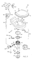
- FIG. 3 is a partial exploded view of structures of an example toilet incorporating aspects of the present invention.
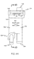
- FIG. 4A is a front view of an example vacuum breaker diverter from FIG. 3;
- FIG. 4B is a partial sectional view along line 4B-4B of the example vacuum breaker diverter of FIG. 4A;
- FIG. 4C is a top view of the example vacuum breaker diverter of FIG. 4A.
- FIG. 4D is a sectional view of the example vacuum breaker along line 4D-4D of FIG 4C.
- FIG. 1 An example embodiment of a toilet apparatus that incorporates aspects of the present invention is shown in the drawings. It is to be appreciated that the shown example is not intended to be a limitation on the present invention. For example, one or more aspects of the present invention can be utilized in other embodiments and even other types of toilets.
- Toilet apparatus 50 in accordance with the present invention can include one or a plurality of structures shown in FIG. 3.
- the toilet apparatus can be incorporated as part of a toilet 51 shown in a simplified, schematic form.
- Various types of toilets can be configured for use in various vehicles, such as, for example, boats, ships, or recreational vehicles, and can also be adapted for use in a stationary structure, such as a home or other building.
- the toilet 51 can include a main body portion 52 having a toilet bowl 54 adapted to receive excrement (not shown), debris, and/or fluid from a user (not shown).
- the main body portion 52 can include various rigid materials, such as, for example, ceramic, porcelain, metal, and/or plastic.
- the toilet bowl 54 includes a first opening 56 disposed towards the top of the main body portion 52 and a second opening 58 disposed towards the bottom of the main body portion 52.
- the first opening 56 can be adapted to receive excrement (not shown), debris and or fluids from a user (not shown) and the second opening 58 can be adapted to permit the excrement, debris (not shown) and/or a fluid to exit the bowl 54.
- the bowl 54 has a generally concave configuration, adapted to direct the excrement, debris, and/or fluids from the first opening 56 towards the second opening 58.
- the toilet 51 can use a fluid (not shown) to clean the toilet bowl 54 during a flushing cycle.
- the fluid comprises water but, in addition or alternatively, may include various fluids capable of flushing the excrement and/or other debris (not shown) from the bowl 54.
- fluid may comprise a single fluid type, a mixture of fluid types, or a mixture of solids and fluids.
- the fluid 54 may consist of water, a detergent, holding tank additive and/or the like.
- the fluid can be supplied to the toilet 51 by a fluid source 60, shown schematically in FIG. 3.
- the fluid source 60 can be pressurized such that the fluid is caused to flow towards the toilet 51.
- the fluid source 60 can be pressurized by a remote source, such as by a suitable pressure system located on a vehicle or by suitable structure connected to a municipal water supply.
- the fluid source 60 can also be located in a holding tank capable of being pressurized to provide a pressurized fluid source.
- the fluid source 60 comprises a pressurized water source, though, as discussed above, the fluid can be a single fluid type, a mixture of fluid types, or a mixture of solids and fluids.
- the separate components of the mixture need not all originate from the fluid source 60, but instead may be added and/or mixed before entering the toilet 51.
- the toilet 51 can include appropriate structure (not shown) adapted to mix the various components to achieve a desired fluid mixture.
- the main body portion 52 can further include a fluid dispenser 62 for dispensing the fluid for cleaning the toilet bowl 54.
- the fluid dispenser 62 can be incorporated in a toilet rim 64 surrounding the toilet bowl 54.
- the fluid dispenser may be incorporated in other surfaces of the toilet bowl 54 and may even be located near or within the second opening 58.
- the fluid dispenser can also comprise a separate device or may be incorporated as part of the toilet and can be adapted to dispense fluid in a wide range of manners.
- the fluid dispenser 62 can include a hole (not shown), or a plurality of holes, in the toilet rim 64 to allow the fluid to pass from the toilet rim 64 and into the toilet bowl 54.
- the fluid dispenser 62 can comprise a nozzle having a spout (not shown), or a plurality of nozzles having a plurality of spouts (not shown). It is to be appreciated that the fluid dispenser can also comprise a wide range of further structures and configurations designed to dispense a liquid into the toilet bowl 54.
- fluid from the fluid source 60 can be released into the toilet bowl 54 by the opening of a flush valve 66.
- the flush valve 66 can be placed in fluid communication with the fluid source 60 and can be normally biased to a closed position.
- the flush valve 66 can be opened in various manners.
- a foot pedal 68 can be operably connected to the flush valve 66 to allow hands-free opening of the flush valve.
- the flush valve 66 can be provided with a lever, a push button, a chain pull, or other structure.
- the toilet 51 can further include any number of elements to compliment functionality and installation of the toilet.
- the toilet 51 can include a lid 70 adapted to cover the toilet bowl 54.
- the toilet 51 can also include a seat 72 (shown in part) adapted to permit a user to sit upon the toilet 51.
- the lid 70 and/or seat 72 if provided, can be pivotally attached to the toilet 51 by one or more hinges 74.
- the toilet 51 can also include mounting structure 76 adapted to mount the toilet 51 to a drain (not shown).
- the mounting structure 76 can include a seal 77 adapted to provide a sealed connection between a base portion 78 of the toilet 51 and a discharge valve housing 80.
- the base portion 78 of the toilet 51 can be in fluid communication with the second opening 58 of the toilet bowl 54, and the discharge valve housing 80 can be in fluid communication with a flange 82.
- the flange 82 can be adapted to attach to the drain (not shown), to thereby provide a discharge pathway for the excrement, debris and/or fluid out of the toilet bowl 54.
- the base portion 78 of the toilet 51 can be secured to the discharge valve housing 80 by way of a clamping member 84.
- the clamping member 84 can include a clamp element 86 and a retainer member 88. As shown, two semi-circular clamp elements 86 can be adapted to engage corresponding structure of the base portion 78 and the discharge valve housing 80. Next, the retainer member 88 can be adapted to fit around the clamp elements 86 and tightened to maintain a sealed connection between the base portion 78 and the discharge valve housing 80.
- the retainer member can comprise various retainers, such as, for example, a hose clamp.
- the discharge valve housing 80 can be secured to the flange 82, for example, with fasteners.
- a gasket 90 can also be disposed between the discharge valve housing 80 and the flange 82 to provide a sealed connection therebetween.
- the discharge valve housing 80 can include a discharge valve 92.
- the discharge valve 92 can be adapted to selectively close the communication between the base portion 78 of the toilet 51 and the drain (not shown).
- any contents of the toilet bowl 54 e.g., excrement, debris, and/or fluid
- the toilet 51 can further include linkage structure 94 adapted to open the discharge valve 92 automatically upon an opening of the flush valve 66. Upon opening the discharge valve 92, any excrement, debris, and/or fluid contained within the toilet bowl 54 can be directed towards the drain (not shown).
- the linkage structure 94 can be adapted to permit a user to manually open the discharge valve 92.
- the toilet 51 can include a discharge valve cover 96 adapted to enclose the discharge valve housing 80 and/or the linkage structure 94.
- the toilet apparatus 50 can further include a spraying apparatus 100 having a spray valve 102 biased to a closed position.
- the spraying apparatus 100 can be adapted to dispense the fluid upon opening of the spray valve 102.
- the spraying apparatus 100 comprises a hand sprayer 104 that can include a grip portion 106 adapted to permit a user to easily manipulate the hand sprayer 104 during use.
- the hand sprayer 104 can be provided with a trigger 108 to open the spray valve 102.
- the spraying apparatus 100 is not intended to be limited to a hand sprayer, and can comprise various other types of spraying apparatus having various geometries.
- the spraying apparatus 100 can include a nozzle 110.
- the nozzle 110 is disposed at one end of the hand sprayer 104 and can be adapted to discharge a fluid away from the user.
- the nozzle 110 can be designed to produce various spray patterns such as a focused jet spray to perform high-pressure cleaning operations.
- the nozzle 110 can be designed to restrict liquid flow and/or provide a dispersed pattern to perform low-pressure cleaning operations.
- the spraying apparatus 100 can also include a plurality of nozzles 110 forming various types of spray patterns.
- a plurality of nozzles 110 including a plurality of jets can form a plurality of jet sprays configured to perform various high-pressure and/or low-pressure cleaning operations.
- the spraying apparatus 100 can further be provided with a storage unit 112.
- the storage unit 112 can include an aperture 114 adapted to receive a portion of the spraying apparatus.
- the aperture 114 can be adapted to receive the grip portion 106.
- the storage unit 112 can be adapted to engage various portions of the spraying apparatus 100 to store it while it is not in use. Further still, the storage unit 112 can be adapted to mount to a wall (as shown), the toilet 51, or various other structures.
- the toilet apparatus 50 includes a vacuum breaker diverter 116 in fluid communication with at least the flush valve 66, the fluid dispenser 62, and the spraying apparatus 100.
- the vacuum breaker diverter 116 can be in fluid communication with the flush valve 66, the fluid dispenser 62, and the spraying apparatus 100 through a first conduit 118, a second conduit 120, and a third conduit 122, respectively.
- the conduits 118, 120, 122 can include flexible and/or non-flexible materials.
- the third conduit 122 can include a flexible material to permit a user to easily manipulate the hand sprayer 104.
- the vacuum breaker diverter 116 can receive fluid from additional sources, and/or can supply fluid to additional elements.
- the vacuum breaker diverter 116 is located downstream of the flush valve 66 although other configurations may be provided in further examples.
- the vacuum breaker diverter 116 can be adapted to direct substantially all of a fluid stream from the flush valve 66 to the fluid dispenser 62 while the flush valve 66 is open and the spray valve 102 is closed. Additionally, the vacuum breaker diverter 116 can direct at least a substantial portion of the fluid stream from the flush valve 66 to the spraying apparatus 100 when the flush valve 66 is open and the spray valve 102 is open. For example, although not required in each embodiment of the invention, the vacuum breaker diverter 116 can be adapted to direct greater than 41 % of a fluid stream from the flush valve 66 to the spraying apparatus 100 while the flush valve 66 is open and the spray valve 102 is open.
- the vacuum breaker diverter 116 can be adapted to direct at least about 45% of a fluid stream from the flush valve 66 to the spraying apparatus 100 while the flush valve 66 is open and the spray valve 102 is open. In a further example, the vacuum breaker diverter 116 can be adapted to direct at least about 55% of a fluid stream from the flush valve 66 to the spraying apparatus 100 while the flush valve 66 is open and the spray valve 102 is open. In yet another example, the vacuum breaker diverter 116 can be adapted to direct at least about 65% of a fluid stream from the flush valve 66 to the spraying apparatus 100 while the flush valve 66 is open and the spray valve 102 is open. In still further examples, the vacuum breaker diverter 116 can be adapted to direct at least about 67% of a fluid stream from the flush valve 66 to the spraying apparatus 100 while the flush valve 66 is open and the spray valve 102 is open.
- the vacuum breaker diverter 116 can include a vacuum breaker portion 124 that can be adapted to prevent an underpressure condition in the system after a flush cycle. Further, the vacuum breaker diverter 116 can include a diverter portion 126 (see FIG. 4B) that can be adapted to divert substantially all of a fluid stream to the fluid dispenser 62, or at least a substantial portion of a fluid stream to the spraying apparatus 100 as discussed above.
- the vacuum breaker portion 124 can have a first chamber 132 having a first opening 134 adapted to receive water from the water source 60.
- the first opening 134 can be in fluid communication with the flush valve 66 through the first conduit 118.
- the vacuum breaker portion 124 can also have a second chamber 136 that can be in fluid communication with a second opening 138 and a third opening 140 through a chamber opening 137.
- the second opening 138 can be in fluid communication with the fluid dispenser 62 through the second conduit 120
- the third opening 140 can be in fluid communication with the spraying apparatus 100 through the third conduit 122.
- the vacuum breaker portion 124 can further comprise a check valve 142 in fluid communication with the flush valve 66.
- the check valve 142 can be adapted to inhibit backflow from either the spraying apparatus 100 or the fluid dispenser 62 after a flushing operation.
- the check valve 142 can comprise a poppet valve or various other valves adapted to inhibit backflow.
- the check valve 142 can include a seal 144 adapted to seal the first chamber 132 from the second chamber 136.
- the seal 144 can be fixedly or removably attached to the check valve 142 in various manners, such as through a pin 145 or other fastener.
- the vacuum breaker portion can comprise various structures configured to prevent an underpressure condition within the second chamber 136.
- the illustrated vacuum breaker portion comprises a cover plate 146 adapted to provide a cover for the second chamber 136.
- the cover plate 146 can include an atmospheric vent 148 adapted to prevent an underpressure condition (e.g., a vacuum) from developing within the second chamber 136.
- an underpressure condition e.g., a vacuum
- the cover plate 146 as shown is not intended to provide any limitations upon the present invention, and that any cover plate 146 having various (or multiple) atmospheric vent(s) 148 can be used.
- the vacuum breaker diverter 116 can also include other structure.
- it can include a mounting bracket 143 adapted to mount the vacuum breaker diverter 116 to structures, such as, for example, the toilet 51 or the wall of a building or vehicle (not shown).
- the vacuum breaker diverter 116 can be removably or permanently mounted in various manners.
- the vacuum breaker diverter 116 can include an indicator 147 adapted to indicate the centerline of the seal 144.
- an indicator 147 can be used to ensure that the vacuum breaker diverter 116 is substantially level when it is mounted to the toilet 51 or other structure (not shown) to thereby achieve good performance of the vacuum breaker portion 126.
- the seal 144 can include various structure adapted to seal against the first chamber 134 and/or the atmospheric vent 148, such as, for example, a lip or a groove (not shown).
- fluid can enter the first chamber 132 from the first opening 134 when the flush valve 66 is actuated.
- the inflow of the pressurized fluid can cause the check valve 142 to move in an upward direction until the seal 144 sealingly engages the atmospheric vent 148.
- the fluid can then flow from the first chamber 132 and into the second chamber 136, where the diverter portion 126 can divert the fluid stream to the fluid dispenser 62 or the spraying apparatus 100, as described more fully herein.
- the check valve 142 can return to its initial position and sealingly engage the first chamber 132.
- the check valve 142 can return to its initial position by the force of gravity, although the check valve 142 can be resiliently biased towards the first chamber 132 with a spring or other biasing member.
- the check valve 142 can be resiliently biased towards the first chamber 132 with a spring or other biasing member.
- atmospheric air can enter through the atmospheric vent 148 to prevent an underpressure condition within the second chamber 136.
- the diverter portion 126 can be adapted to divert at least a substantial portion of the fluid stream from the flush valve 66 to the spraying apparatus 100 when the flush valve 66 and the spray valve 102 are opened.
- the diverter portion 126 can be adapted to divert greater than 41%, at least about 45%, at least about 55%, at least about 65%, and/or at least about 67% of a fluid stream to the spraying apparatus 100 when the flush valve 66 and the spray valve 102 are opened.
- the diverter portion 126 can comprise a diverter chamber 152 and at least one diverter device 150 movable within the diverter chamber 152.
- the diverter device 150 can be capable of selectively directing the fluid to at least the fluid dispenser 62 or the spraying apparatus 100.
- the diverter device 150 can be configured to move within the diverter chamber 152 between a first position (shown in FIG. 4B) when the flush valve 66 is open and the spray valve 102 is closed.
- the diverter device 150 can also shift to the right (from the position shown in FIG. 4B) to a second position when the flush valve 66 is open and the spray valve 102 is open.
- the diverter chamber 152 can be in fluid communication with the second chamber 136 through the chamber opening 137.
- the diverter chamber 152 can also be in fluid communication with the second opening 138 through a flush chamber 154, and the third opening 140 through a spraying chamber 156.
- the third opening 140 can be part of a spraying tube 158 sealingly attached to the spraying chamber 156, or alternatively it can be formed with the spraying chamber 156.
- the spray valve 102 of the spraying apparatus 100 can be in fluid communication with the spraying tube 158 through the third conduit 122.
- the diverter device 150 can comprise a diverter piston 151.
- the diverter device 150 can comprise other structure, such as may be found in, for example, a globe valve, a ball valve, and/or a butterfly valve.
- the diverter piston 151 if provided, can include a first diverter seal 160 and a second seal 162.
- the diverter seals 160, 162 can be fixedly or removably attached to the diverter piston 151 in various manners.
- the diverter seals 160, 162 can include various materials adapted to provide a seal between the diverter chamber 152 and the flush and/or spraying chambers 154, 156.
- the diverter seals 160, 162 can include plastic, rubber, and or metal.
- either, or both, of the diverter seals 160, 162 can be formed with the diverter piston 150.
- the diverter seals 160, 162 can include other structure adapted to provide a seal between the diverter chamber 152 and the flush and/or spraying chambers 154, 156.
- the diverter seals 160, 162 can include o-rings, or the like.
- the first and second diverter seals 160, 162 of the diverter piston 151 can be adapted to seal against first and second surfaces, respectively, of the vacuum breaker diverter 116.
- the diverter chamber 152 can have a smaller area than the flush chamber 154 to thereby create a first seat 164 for the first diverter seal 160.
- the diverter chamber 152 can have a smaller area than the spraying chamber 156 to create a second seat 166 for the second diverter seal 162.
- first and second diverter seals 160, 162 can be adapted to alternatively sealingly engage the first and second seats 164, 166, respectively, to provide a seal between the diverter chamber 152 and the flush chamber 154 and, alternatively, between the diverter chamber 152 and the spraying chamber 156.
- the first and second seats 164, 166 can have a circular geometry, and the diverter seals 160, 162 can have a corresponding frusto-conical geometry adapted to sealingly engage the seats 164, 166. That is, a portion of the diverter seals 160, 162 can abut the seats 164, 166 to provide a fluid seal between the diverter chamber 152 and the flush chamber 154 and/or the spraying chamber 156.
- the diverter seals 160, 162 can have a rigid or flexible geometry.
- the first diverter seal 160 as shown, can have a substantially solid geometry that can provide a rigid seal.
- the diverter seal 160 is designed to seal against the seat 164 when the diverter piston 151 is in the second position (shifted to the right).
- the second diverter seal 162, as shown, can include both a base portion 168 and a flexible portion 170.
- the base portion 168 can have a substantially solid geometry adapted to sealingly engage the second seat 166 in the illustrated first position.
- the flexible portion 170 can have a solid configuration, or, as shown, can include a groove 172 adapted to permit portions of the second diverter seal 162 to flex and bias against the inner surface of the spraying chamber 156 at each position of the diverter piston within the diverter chamber. Further still, the diverter seals 160, 162 can include portions that are larger than the first and second seats 164, 166 so as to prevent backflow into the diverter chamber 152 from either of the flushing chamber 154 and/or the spraying chamber 156.
- the diverter piston 151 can be adapted to selectively move either the first or second diverter seals 160, 162 into sealing engagement with the first or second seats 164, 166.
- the base portion 168 of the second diverter seal 162 engages the second seat 166 when the diverter piston is moved to the first position.
- diverter piston 151 may be shifted to the right to the second position wherein the first diverter seal 160 engages the first seat 164.
- the diverter device can be configured to move within the diverter chamber between a first position when the flush valve is open and the spray valve is closed and a second position when the flush valve is open and the spray valve is open.
- the diverter device can move in a wide variety of ways from the first to second position.
- the diverter device can reciprocate, translate, move along a linear or nonlinear path, pivot, rotate and/or otherwise move within the diverter chamber.
- the diverter piston 151 is configured to reciprocate, translate, and move along a linear path 153 within the diverter chamber 152 from a first position (shown in FIG. 4B) when the flush valve 66 is open and the spray valve 102 is closed and a second position (shifted to the right from FIG. 4B), when the flush valve 66 is open and the spray valve 102 is open.
- pressurized fluid from the fluid source 60 e.g., water or fluid mixture
- the fluid can flow through the vacuum breaker portion 124 as discussed above to prevent an underpressure condition in the system after a flush cycle.
- the fluid can then flow through the diverter portion 126 by passing through the chamber opening 137 of the second chamber 136 and into the diverter chamber 152.
- the diverter portion 126 is adapted to direct substantially all of the fluid to the fluid dispenser 62.
- the force supplied by the pressurized fluid can bias the diverter piston 151 to the first position shown in FIG. 4B wherein the second seal 170 seals against the second seat 166.
- the fluid stream can then flow around the first seal 160 and through the second conduit 120 to the main body portion 52 of the toilet 51.
- the fluid dispenser 62 then dispenses the fluid stream into the toilet bowl 54.
- a spring or other resilient member can resiliently bias the diverter piston 151 to one of the first or second positions.
- the flush valve 66 can also actuate the discharge valve 92 to an open position to provide a discharge pathway for the fluid, excrement, and/or debris.
- the diverter portion 126 can be adapted to direct at least a substantial portion of the fluid to the spraying apparatus 100 through the third conduit 122.
- a force differential acting the diverter device 150 can shift the diverter piston 151 to the right from the first position illustrated in FIG. 4B to the second position (not shown) wherein the first diverter seal 160 seals against the first seat 164. Once the first diverter seal 160 seals against the first seat 164, at least a substantial portion of the fluid stream is directed to the spraying apparatus 100 and at least a portion of fluid stream is inhibited from passing to the fluid dispenser 62.
- the force from the pressurized fluid can compress the flexible portion 170 of the second diverter seal 162 to permit the fluid to flow around the second diverter seal 162 and into the spraying tube 158.
- the fluid can then flow out of the third opening 140 and through the third conduit 122, out of the nozzle 110 of the spraying apparatus 100.
- the flexible portion 170 of the second diverter seal 162 can be resiliently biased outwards to thereby prevent any backflow from fluid remaining in the third conduit 122 and/or the spraying tube 158.
- the flush valve 66 can be adapted to provide fluid from the fluid source 60 to the vacuum breaker diverter 116 so long as the flush valve 66 is open. For example, a user can keep the flush valve 66 opened for an extended period of time if it is desired to use the spraying apparatus 100 in a continuous manner. Further, when a user is using the spraying apparatus 100 and subsequently closes the spray valve 102, the force supplied by the pressurized fluid can then bias the diverter piston 151 and the first diverter seal 160 back towards the first position (shown in FIG. 4B) such that substantially all of the fluid flow is discharged out of the fluid dispenser 62.
- a user can use the spraying apparatus 100 to clean the toilet bowl 54. It is to be appreciated that the user can also use the spraying apparatus 100 to clean other items. As features of the present invention permit at least a substantial portion of the pressurized fluid to be dispensed by the spraying apparatus 100, it may be possible to effectively clean the toilet bowl 54 with less water as opposed to using solely the fluid dispenser 62.
Landscapes
- Engineering & Computer Science (AREA)
- Health & Medical Sciences (AREA)
- Public Health (AREA)
- Life Sciences & Earth Sciences (AREA)
- Hydrology & Water Resources (AREA)
- Water Supply & Treatment (AREA)
- Aviation & Aerospace Engineering (AREA)
- Epidemiology (AREA)
- Mechanical Engineering (AREA)
- Molecular Biology (AREA)
- Sanitary Device For Flush Toilet (AREA)
Applications Claiming Priority (2)
| Application Number | Priority Date | Filing Date | Title |
|---|---|---|---|
| US74007205P | 2005-11-28 | 2005-11-28 | |
| US11/438,802 US20070118981A1 (en) | 2005-11-28 | 2006-05-23 | Toilet apparatus with a vacuum breaker diverter |
Publications (2)
| Publication Number | Publication Date |
|---|---|
| EP1790783A2 true EP1790783A2 (fr) | 2007-05-30 |
| EP1790783A3 EP1790783A3 (fr) | 2010-05-05 |
Family
ID=37775285
Family Applications (1)
| Application Number | Title | Priority Date | Filing Date |
|---|---|---|---|
| EP06018359A Withdrawn EP1790783A3 (fr) | 2005-11-28 | 2006-09-01 | Toilette avec distributeur d'eau de chasse |
Country Status (2)
| Country | Link |
|---|---|
| US (1) | US20070118981A1 (fr) |
| EP (1) | EP1790783A3 (fr) |
Cited By (3)
| Publication number | Priority date | Publication date | Assignee | Title |
|---|---|---|---|---|
| ITRM20130376A1 (it) * | 2013-06-28 | 2014-12-29 | Gioele Columbro | Bidet portatile |
| CN106988396A (zh) * | 2017-04-11 | 2017-07-28 | 广州赛特环保工程有限公司 | 高寒地区真空厕所污物收集及排放系统 |
| USD1058777S1 (en) * | 2024-05-06 | 2025-01-21 | Hesong Yu | Portable bidet |
Families Citing this family (5)
| Publication number | Priority date | Publication date | Assignee | Title |
|---|---|---|---|---|
| US9879410B2 (en) * | 2011-03-10 | 2018-01-30 | Zhenrong W. Yeh | Cold bathing water to toilet diverting apparatus |
| US20190161952A1 (en) * | 2017-11-28 | 2019-05-30 | Mosab Ramzi Muhi Deen | Portable bidet module |
| JP2020002567A (ja) * | 2018-06-26 | 2020-01-09 | パナソニックIpマネジメント株式会社 | 給水装置 |
| JP7199031B2 (ja) * | 2018-06-26 | 2023-01-05 | パナソニックIpマネジメント株式会社 | 給水装置 |
| US12577769B2 (en) | 2023-07-03 | 2026-03-17 | Home Biogas Ltd | Environmentally sustainable systems and methods of toilet flushing and blackwater disposal |
Family Cites Families (31)
| Publication number | Priority date | Publication date | Assignee | Title |
|---|---|---|---|---|
| US1864827A (en) * | 1931-10-02 | 1932-06-28 | Clifford W Jenkins | Sanitary toilet flush |
| US2703408A (en) * | 1952-04-28 | 1955-03-08 | Gray Dev Company | Apparatus for rinsing bedpans |
| US2956285A (en) * | 1958-12-19 | 1960-10-18 | American Sterilizer Co | Bed pan rinsing structure |
| US3419911A (en) * | 1966-03-01 | 1969-01-07 | American Sterilizer Co | Wall cabinet and water closet combination |
| US3471872A (en) * | 1966-09-21 | 1969-10-14 | Symmons Eng Co | Plumbing fixture for baths |
| US3629872A (en) * | 1970-07-06 | 1971-12-28 | American Standard Inc | Bed pan rinser |
| US3646617A (en) * | 1970-09-24 | 1972-03-07 | Jerome Ingles Heald | Bedpan washer with pistol-type nozzle |
| FR2178764B1 (fr) * | 1972-04-04 | 1974-08-02 | Ibm France | |
| US3855640A (en) * | 1973-10-23 | 1974-12-24 | Sloan Valve Co | Bedpan rinser apparatus |
| US3964108A (en) * | 1974-11-20 | 1976-06-22 | Sloan Valve Company | Deoseptic assembly for bedpan rinser |
| US4183105A (en) * | 1977-11-03 | 1980-01-15 | Womack Leo K | Self-cleaning toilet |
| US4326671A (en) * | 1980-02-05 | 1982-04-27 | Goguen Robert P | Anti-siphon selector valve |
| US4589438A (en) * | 1983-02-14 | 1986-05-20 | Silvano Breda | Diverter valve with integral atmospheric type vacuum breaker |
| US4874006A (en) * | 1989-01-26 | 1989-10-17 | Kohler Co. | Diverter valve and vacuum breaker usable therewith |
| CA1296597C (fr) * | 1989-03-31 | 1992-03-03 | Pietro Rollini | Robinet de derivation pour baignoire/douche a soupape casse-vide et clapet anti-retour |
| US5206769A (en) * | 1990-04-20 | 1993-04-27 | International Business Machines Corporation | Method for controlling a plurality of phase-lock loops from a common frequency control |
| US5063619A (en) * | 1990-06-01 | 1991-11-12 | U.S. Tap, Inc. | Vacuum breaker for bidet |
| US5199115A (en) * | 1991-10-21 | 1993-04-06 | Sloan Valve Company | Bedpan rinsing apparatus arm assembly seal |
| IT1269425B (it) * | 1994-01-13 | 1997-04-01 | Eco Program Srl | Disposizione e procedimento per pulire automaticamente un apparecchio sanitario |
| US5738135A (en) * | 1994-12-19 | 1998-04-14 | Ecolab Inc. | Dispensing apparatus with line pressure diverter |
| US5655563A (en) * | 1994-12-19 | 1997-08-12 | Ecolab Inc. | Dispensing apparatus with line pressure diverter |
| US5970534A (en) * | 1995-02-21 | 1999-10-26 | Silvano Breda | Diverter valves with integral back flow preventer and inlet check and outlet check valve mechanisms and improvements therefor |
| US5701934A (en) * | 1996-02-02 | 1997-12-30 | V. A. Butler, Inc. | Rotary diverter valve |
| US5845670A (en) * | 1996-02-26 | 1998-12-08 | Perani, Inc. | Diverter valve with vacuum breaker |
| US6789552B1 (en) * | 2000-09-14 | 2004-09-14 | Kaivac, Inc. | Method of cleaning a toilet |
| US6718664B2 (en) * | 2002-01-03 | 2004-04-13 | Williams Industries | Container having image-carrying sheet and method of manufacturing such container |
| DE20206465U1 (de) * | 2002-04-24 | 2002-08-14 | Junghardt, Siegmund, 42287 Wuppertal | Wasserspülung mit zusätzlichem dosierbaren Wasserstrahl |
| US7077153B2 (en) * | 2002-07-17 | 2006-07-18 | Newfrey Llc | Side control faucet with diverter assembly |
| CA2424405C (fr) * | 2003-04-03 | 2009-07-28 | Silvano Breda | Inverseur avec cartouche amovible comprenant casse vide et clapet antiretour integres |
| US7013502B2 (en) * | 2003-10-27 | 2006-03-21 | Manuel A Pacheco | Bidet |
| US6941590B2 (en) * | 2003-12-09 | 2005-09-13 | Howard Tak Su Lim | Toilet system attached a multi-purpose hand held sprayer |
-
2006
- 2006-05-23 US US11/438,802 patent/US20070118981A1/en not_active Abandoned
- 2006-09-01 EP EP06018359A patent/EP1790783A3/fr not_active Withdrawn
Cited By (3)
| Publication number | Priority date | Publication date | Assignee | Title |
|---|---|---|---|---|
| ITRM20130376A1 (it) * | 2013-06-28 | 2014-12-29 | Gioele Columbro | Bidet portatile |
| CN106988396A (zh) * | 2017-04-11 | 2017-07-28 | 广州赛特环保工程有限公司 | 高寒地区真空厕所污物收集及排放系统 |
| USD1058777S1 (en) * | 2024-05-06 | 2025-01-21 | Hesong Yu | Portable bidet |
Also Published As
| Publication number | Publication date |
|---|---|
| EP1790783A3 (fr) | 2010-05-05 |
| US20070118981A1 (en) | 2007-05-31 |
Similar Documents
| Publication | Publication Date | Title |
|---|---|---|
| US11155987B2 (en) | Bidet washing apparatus with disinfectant wash feature | |
| US11692337B2 (en) | Bidet washing apparatus with disinfectant wash feature | |
| US11814834B2 (en) | Bidet washing apparatus with disinfectant wash feature | |
| US4246666A (en) | Flush toilet | |
| US6675399B1 (en) | Tankless toilet, western-style flush toilet, private part washing device and spud for flush toilet | |
| US20100125940A1 (en) | Toilet for use in recreational vehicle and boats | |
| US11879243B2 (en) | Bidet washing apparatus with disinfectant wash feature | |
| US12378756B2 (en) | Bidet washing apparatus with disinfectant wash feature | |
| KR100327630B1 (ko) | 이동식진공변기시스템 | |
| US4471798A (en) | Flushing cisterns | |
| US20010007158A1 (en) | Flushing device for a toilet | |
| CN108903738B (zh) | 防回流组件和分配器 | |
| US20080244819A1 (en) | Self-plunging toilet and method of clearing a toilet | |
| EP1790783A2 (fr) | Toilette avec distributeur d'eau de chasse | |
| GB2243379A (en) | Water saving attachment for valve-discharge W.C. cistern | |
| JPS5928707B2 (ja) | 水洗便器 | |
| EP0414884A1 (fr) | Appareil de wc a chasse sous vide a commande manuelle | |
| US20040139544A1 (en) | Diverter assembly for roman tub | |
| US6073273A (en) | Venting apparatus for flush toilets | |
| US12442172B2 (en) | Bidet washing apparatus with disinfectant wash feature | |
| FR2918687A1 (fr) | Dispositif hydraulique retractable et auto-nettoyant d'ejection d'eau equipant un abattant de water-closet pour hygiene intime | |
| EP4273335B1 (fr) | Distributeur pour bidet | |
| US20070017011A1 (en) | Chemical administrator for treating wastewater from a water-consuming device in a self-contained bathroom system | |
| WO1999016983A1 (fr) | Dispositif de lavage sanitaire | |
| CA1094253A (fr) | Cabinet d'aisances a chasse par le vide |
Legal Events
| Date | Code | Title | Description |
|---|---|---|---|
| PUAI | Public reference made under article 153(3) epc to a published international application that has entered the european phase |
Free format text: ORIGINAL CODE: 0009012 |
|
| AK | Designated contracting states |
Kind code of ref document: A2 Designated state(s): AT BE BG CH CY CZ DE DK EE ES FI FR GB GR HU IE IS IT LI LT LU LV MC NL PL PT RO SE SI SK TR |
|
| AX | Request for extension of the european patent |
Extension state: AL BA HR MK YU |
|
| RAP1 | Party data changed (applicant data changed or rights of an application transferred) |
Owner name: DOMETIC CORPORATION |
|
| PUAL | Search report despatched |
Free format text: ORIGINAL CODE: 0009013 |
|
| AK | Designated contracting states |
Kind code of ref document: A3 Designated state(s): AT BE BG CH CY CZ DE DK EE ES FI FR GB GR HU IE IS IT LI LT LU LV MC NL PL PT RO SE SI SK TR |
|
| AX | Request for extension of the european patent |
Extension state: AL BA HR MK RS |
|
| 17P | Request for examination filed |
Effective date: 20100923 |
|
| 17Q | First examination report despatched |
Effective date: 20101126 |
|
| AKX | Designation fees paid |
Designated state(s): AT BE BG CH CY CZ DE DK EE ES FI FR GB GR HU IE IS IT LI LT LU LV MC NL PL PT RO SE SI SK TR |
|
| STAA | Information on the status of an ep patent application or granted ep patent |
Free format text: STATUS: THE APPLICATION IS DEEMED TO BE WITHDRAWN |
|
| 18D | Application deemed to be withdrawn |
Effective date: 20110407 |