EP1790786A1 - Montierbare Gerüststruktur zum Aufbau eines Zeltgerüsts oder einer anderen Abdeckung in verschiedenen Formen - Google Patents
Montierbare Gerüststruktur zum Aufbau eines Zeltgerüsts oder einer anderen Abdeckung in verschiedenen Formen Download PDFInfo
- Publication number
- EP1790786A1 EP1790786A1 EP06370034A EP06370034A EP1790786A1 EP 1790786 A1 EP1790786 A1 EP 1790786A1 EP 06370034 A EP06370034 A EP 06370034A EP 06370034 A EP06370034 A EP 06370034A EP 1790786 A1 EP1790786 A1 EP 1790786A1
- Authority
- EP
- European Patent Office
- Prior art keywords
- profile
- adaptable
- structure according
- beams
- panels
- Prior art date
- Legal status (The legal status is an assumption and is not a legal conclusion. Google has not performed a legal analysis and makes no representation as to the accuracy of the status listed.)
- Withdrawn
Links
- 238000010276 construction Methods 0.000 claims description 11
- 210000002105 tongue Anatomy 0.000 claims description 7
- 230000000712 assembly Effects 0.000 claims 1
- 238000000429 assembly Methods 0.000 claims 1
- 238000009432 framing Methods 0.000 abstract 1
- 229920002635 polyurethane Polymers 0.000 description 3
- 239000004814 polyurethane Substances 0.000 description 3
- 241001272720 Medialuna californiensis Species 0.000 description 2
- 239000006260 foam Substances 0.000 description 2
- 239000000463 material Substances 0.000 description 2
- 229920005830 Polyurethane Foam Polymers 0.000 description 1
- 238000004026 adhesive bonding Methods 0.000 description 1
- 229910052782 aluminium Inorganic materials 0.000 description 1
- XAGFODPZIPBFFR-UHFFFAOYSA-N aluminium Chemical compound [Al] XAGFODPZIPBFFR-UHFFFAOYSA-N 0.000 description 1
- 229910052751 metal Inorganic materials 0.000 description 1
- 239000002184 metal Substances 0.000 description 1
- 238000000034 method Methods 0.000 description 1
- 238000005192 partition Methods 0.000 description 1
- 239000004033 plastic Substances 0.000 description 1
- 229920003023 plastic Polymers 0.000 description 1
- 239000011496 polyurethane foam Substances 0.000 description 1
- 238000000638 solvent extraction Methods 0.000 description 1
- 239000002023 wood Substances 0.000 description 1
Images


Classifications
-
- E—FIXED CONSTRUCTIONS
- E04—BUILDING
- E04H—BUILDINGS OR LIKE STRUCTURES FOR PARTICULAR PURPOSES; SWIMMING OR SPLASH BATHS OR POOLS; MASTS; FENCING; TENTS OR CANOPIES, IN GENERAL
- E04H15/00—Tents or canopies, in general
- E04H15/18—Tents having plural sectional covers, e.g. pavilions, vaulted tents, marquees, circus tents; Plural tents, e.g. modular
-
- E—FIXED CONSTRUCTIONS
- E04—BUILDING
- E04B—GENERAL BUILDING CONSTRUCTIONS; WALLS, e.g. PARTITIONS; ROOFS; FLOORS; CEILINGS; INSULATION OR OTHER PROTECTION OF BUILDINGS
- E04B1/00—Constructions in general; Structures which are not restricted either to walls, e.g. partitions, or floors or ceilings or roofs
- E04B1/38—Connections for building structures in general
- E04B1/61—Connections for building structures in general of slab-shaped building elements with each other
- E04B1/6108—Connections for building structures in general of slab-shaped building elements with each other the frontal surfaces of the slabs connected together
- E04B1/612—Connections for building structures in general of slab-shaped building elements with each other the frontal surfaces of the slabs connected together by means between frontal surfaces
- E04B1/6183—Connections for building structures in general of slab-shaped building elements with each other the frontal surfaces of the slabs connected together by means between frontal surfaces with rotatable locking means co-operating with a recess
-
- E—FIXED CONSTRUCTIONS
- E04—BUILDING
- E04B—GENERAL BUILDING CONSTRUCTIONS; WALLS, e.g. PARTITIONS; ROOFS; FLOORS; CEILINGS; INSULATION OR OTHER PROTECTION OF BUILDINGS
- E04B1/00—Constructions in general; Structures which are not restricted either to walls, e.g. partitions, or floors or ceilings or roofs
- E04B1/38—Connections for building structures in general
- E04B1/61—Connections for building structures in general of slab-shaped building elements with each other
- E04B2001/6195—Connections for building structures in general of slab-shaped building elements with each other the slabs being connected at an angle, e.g. forming a corner
Definitions
- the invention relates to a building structure, able to allow the development of a tent frame, including tent called “garden cottage”, or any other tent of various shapes.
- building structure means a construction that can be erected easily, reversibly to be removed quickly. These structures are particularly used in the field of events for the realization of temporary constructions. These can include marquees designed to protect people and / or equipment from the elements.
- These structures have an armature consisting of a set of beams, including metal profiles, arranged vertically in posts, horizontally crosswise, or at an inclined angle to form the trusses of a roof structure.
- the wall walls and the roof walls are constituted by webs, including waterproof attached to said frame.
- the building structure may also be provided with rigid wall elements, in particular in the form of insulating panels.
- Wall elements are also known in the form of an insulating polyurethane panel. These insulating panels are provided at their edge, in the mass, of one or more housings enclosing a rotary hook cam. These hook cams constitute a quick assembly system for securing the panel to another adjacent panel. In particular, the cams with hooks are actuated in rotation by means of a key to engage with a hanging rod of a neighboring panel.
- These panels are manufactured by an overmolding process wherein the housings of the locking systems are prepositioned in a mold. The polyurethane is then injected into the mold in a subsequent step.
- the present invention aims to overcome these disadvantages by providing a building structure having wall elements easily assembled to existing beams.
- the invention relates to a building structure capable of allowing the development of a tent frame, including tent called “garden cottage” or any other capital of various shapes, the structure comprising a set of beams, in particular arranged vertically in poles, horizontally crosswise, or at an angle to form the trusses of a roof structure, characterized in that the constructable structure further comprises wall elements consisting of building panels equipped with rotating cam assembly systems to hook, in that the structure has, in addition, adaptable profiles constituting a mechanical interface between the beams of the structure and the panels, the adaptable profiles having means for attachment to the beams, the adaptable profiles having at least one rod hook for engaging with the rotary cam hook panels, in the locking position d e the cam.
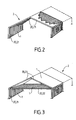
- the building panel 1 can be used indifferently as an element for constituting a wall wall, ceiling, or roof, as shown in Figure 3.
- the panel is equipped with at least one assembly system 3 by rotary cam hook, able to engage, in the locking position, with a tie rod 5 of another structural element, including another panel contiguous construction, the locking system 3 being recessed at one of the edges 6 of the building panel.
- the locking system 3 can be carried by a mounting profile 7 provided to come close one of the edges 6 of the panel and be fixed on the latter.
- the mounting profile 7 can be attached to any type and dimension of building board.
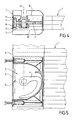
- the panels may be insulating, in particular constituted by polyurethane foam. As illustrated in Figures 4 and 5, the panel may be an insulating sandwich panel made of plastic material and having a multitude of internal partitions, including transverse and longitudinal.
- the mounting profile 7 also allows to position one or more assembly systems 3 at specific positions on the edge of the panel.
- the mounting profile 7 may have at least one section 8 of U-shaped section whose core 9 and the two wings 10 are respectively intended to bear at one of the edges 6 of the panel and to be secured to the two walls of the panel 1.
- the mounting profile can be fixed to the panel by screw, nail; rivet or any other known fastening means or by gluing.
- said at least one assembly system 3 may be integral with the web 9 of the U-section of the profile of FIG. mounting 7, the system being disposed between the wings 10 of the section.
- the core 9 then has at least one opening 11 for the passage of the cam 4 hook.
- the edge 6 of the panel has at least one obviously provided for receiving said at least one assembly system 3.
- the panels of synthetic foam, wood or other material can then be simply nibbled at their edge to create the necessary recesses.
- Foam panels in particular polyurethane, can be peeled off by means of a rotary sander equipped with an abrasive disc for producing a half-moon shaped recess.
- one of the flanges 10 of the U-section of the mounting profile 7 has, in the vicinity of the assembly system 3, an opening 12 for the passage of an operating key of FIG. the hook cam 4.
- the web 9 of the U-section of the mounting profile 7 protrudes laterally from said section at an extension 13.
- the assembly system 3 is integral with the extension 13 to be arranged offset from the plane of the panel 1.
- the extension 13 of the core 9 has at least one opening 14 for the passage of the hook cam 4.
- the assembly system may have, in addition a rod 5, for engaging with the cam a hook 4 of an assembly system 3 of another structural element, including another panel.
- the assembly system 3 may be at least in the form of a housing within which the hook cam 4 is pivotally articulated.
- the housing has at least one opening for the passage of said hook cam 4 and an opening for the passage of an operating key, in particular hexagonal.
- the housings can in particular be of half-moon shape, of diameter equal to the diameter of the abrasive disk used for producing the recesses.
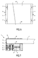
- the panel 1 has two mutually engageable parallel flanges 61, 62, one 61 constituting a male profile, the other 62 constituting a female profile, intended to engage with the female and male edges of two adjacent panels.
- interlocking edges are provided on the edges not bordered by a mounting profile 7.
- the interlocking edges 61, 62 advantageously make it possible to produce the roof or the ceiling of the building structures, by obtaining a better cohesion between the panels.
- the invention relates to a building structure 2 adapted to allow the development of a tent frame, including tent called "garden cottage” or any other tent 15 of various shapes.
- the structure 2 comprises a set of beams 20, in particular arranged vertically in posts 21, horizontally crosswise 22, or at an angle to form the trusses 23 of a roof structure.
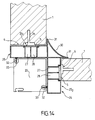
- the building structure furthermore has wall elements constituted by building panels 1 equipped with assembly systems 3 by rotary cam hook 4, the structure also having adaptable profiles 24 constituting a mechanical interface between the beams 20 of the structure and the panels 1, the adaptable profiles having means for attachment to the beams, the adaptable profiles 24 having at least one attachment rod 5 intended to engage with the rotary cam hook 4 panels 1, in the locking position of the cam.
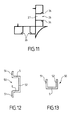
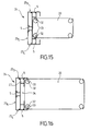
- the adaptable profiles 24 are illustrated in Figures 14 to 16 and advantageously allow to attach to the beams, including pre-existing aluminum profiles.
- the adaptable profile 24 may have at least one bearing surface 25 intended to come into contact with one of the edges 6 of at least one panel 1.
- Each bearing surface 25 has at least one rod 5, disposed perpendicular to the longitudinal axis of said section 24, parallel to the bearing surface 25, received in a first groove 26.
- the groove 26 may be of substantially equal depth to the diameter of the rod 5 in such a way the rod is flush with the bearing surface.
- the profile 24 further has at least one second groove 27, 28, hollowed in said first groove 26 to allow the passage of the cam 4, in the locking position.
- said first groove 26 may have at least two return wings 36 so as to form a rail C.
- the attachment rod 5 is constituted by at least one jumper 50 having at least two lateral surfaces 51, 52. Each of the bearing surfaces is intended to bear against one of the lateral ends of the rail. Said ends are held by the return wings 36, said at least one jumper 50 being inserted by sliding at the open end of the rail.
- the adaptable profile 24 has a generally L-shaped section 29, each of whose wings has at least one bearing surface 25 1 , 25 2 for one of the edges of a panel, to join two panels 1 arranged orthogonal to each other to a beam 20.
- the angled profile may angularly have a rounded profile 30 at the intersection of the two perpendicular bearing surfaces 25 1 , 25 2 , the rounded profile 30 being intended to create a finish angle.
- the rounded profile 30 is also two flat edges intended to abut with the panels 1 and maintain them.
- the adaptable profile 20 has two parallel and opposite bearing surfaces 3 , 25 4 , in order to join two panels 1 arranged parallel to each other to a beam 20.
- the adaptable profile 24 may furthermore present a third support surface 25 5 disposed perpendicularly to the first two surfaces 25 3 , 25 4 and intended to ensure the fixing of panels for partitioning the interior of building structures.
- the fastening means of the adaptable profiles 24 to the beams 20 may consist of tongues 32 longitudinal to said profile 24, intended to be slidably inserted at grooves 33 of the beams 20, in particular otherwise provided for fixing canvas, wall, or roof.
- the longitudinal tongues 32 form the lateral end ends of a rail 34 at C, the tongues 32 being able to engage with two parallel grooves 33 arranged on two parallel and opposite walls of a beam 20.
- the fastening means may consist of two superimposed rails C of a different width in order to allow mounting of the adaptable profile on two beam dimensions.
- the adaptable profile 24 has two longitudinal tongues perpendicular to one another, designed to engage with two grooves 33 arranged on two perpendicular and successive walls of a beam 20.
Landscapes
- Engineering & Computer Science (AREA)
- Architecture (AREA)
- Civil Engineering (AREA)
- Structural Engineering (AREA)
- Physics & Mathematics (AREA)
- Electromagnetism (AREA)
- Tents Or Canopies (AREA)
Applications Claiming Priority (1)
| Application Number | Priority Date | Filing Date | Title |
|---|---|---|---|
| FR0512090A FR2893999A1 (fr) | 2005-11-29 | 2005-11-29 | Structure constructible, apte a permettre l'elaboration d'une charpente de tente, ou tout autre chapiteau de formes diverses |
Publications (1)
| Publication Number | Publication Date |
|---|---|
| EP1790786A1 true EP1790786A1 (de) | 2007-05-30 |
Family
ID=36910966
Family Applications (1)
| Application Number | Title | Priority Date | Filing Date |
|---|---|---|---|
| EP06370034A Withdrawn EP1790786A1 (de) | 2005-11-29 | 2006-11-29 | Montierbare Gerüststruktur zum Aufbau eines Zeltgerüsts oder einer anderen Abdeckung in verschiedenen Formen |
Country Status (2)
| Country | Link |
|---|---|
| EP (1) | EP1790786A1 (de) |
| FR (1) | FR2893999A1 (de) |
Cited By (2)
| Publication number | Priority date | Publication date | Assignee | Title |
|---|---|---|---|---|
| CN103758213A (zh) * | 2014-01-26 | 2014-04-30 | 湖北弘毅钢结构工程有限公司 | 一种装配式墙板与梁体精准定位安装连接结构 |
| CN105040899A (zh) * | 2015-09-06 | 2015-11-11 | 广东菲思科金属科技有限公司 | 铝合金房屋的立柱与墙板及门窗连接结构 |
Citations (4)
| Publication number | Priority date | Publication date | Assignee | Title |
|---|---|---|---|---|
| FR2500113A1 (fr) * | 1981-02-13 | 1982-08-20 | Bouton Michel | Enceinte thermiquement isolante constituee de panneaux modulaires |
| US5038535A (en) * | 1989-06-22 | 1991-08-13 | Praag Iii Alex Van | Fastening device |
| FR2761388A1 (fr) * | 1997-03-25 | 1998-10-02 | Dagard | Poteau d'angle destine au raccordement de deux panneaux de cloisons |
| DE10245498A1 (de) * | 2002-08-07 | 2004-02-19 | Haltec Hallensysteme Gmbh | Planenhaken, System aus Planenhaken und Nutprofil und Verfahren zu deren Verbindung |
-
2005
- 2005-11-29 FR FR0512090A patent/FR2893999A1/fr active Pending
-
2006
- 2006-11-29 EP EP06370034A patent/EP1790786A1/de not_active Withdrawn
Patent Citations (4)
| Publication number | Priority date | Publication date | Assignee | Title |
|---|---|---|---|---|
| FR2500113A1 (fr) * | 1981-02-13 | 1982-08-20 | Bouton Michel | Enceinte thermiquement isolante constituee de panneaux modulaires |
| US5038535A (en) * | 1989-06-22 | 1991-08-13 | Praag Iii Alex Van | Fastening device |
| FR2761388A1 (fr) * | 1997-03-25 | 1998-10-02 | Dagard | Poteau d'angle destine au raccordement de deux panneaux de cloisons |
| DE10245498A1 (de) * | 2002-08-07 | 2004-02-19 | Haltec Hallensysteme Gmbh | Planenhaken, System aus Planenhaken und Nutprofil und Verfahren zu deren Verbindung |
Cited By (3)
| Publication number | Priority date | Publication date | Assignee | Title |
|---|---|---|---|---|
| CN103758213A (zh) * | 2014-01-26 | 2014-04-30 | 湖北弘毅钢结构工程有限公司 | 一种装配式墙板与梁体精准定位安装连接结构 |
| CN103758213B (zh) * | 2014-01-26 | 2015-09-23 | 湖北弘毅钢结构工程有限公司 | 一种装配式墙板与梁体精准定位安装连接结构 |
| CN105040899A (zh) * | 2015-09-06 | 2015-11-11 | 广东菲思科金属科技有限公司 | 铝合金房屋的立柱与墙板及门窗连接结构 |
Also Published As
| Publication number | Publication date |
|---|---|
| FR2893999A1 (fr) | 2007-06-01 |
Similar Documents
| Publication | Publication Date | Title |
|---|---|---|
| CA2385268C (fr) | Structure acoustique de batiment | |
| FR2808826A1 (fr) | Dispositif d'assemblage des bords longitudinaux de panneaux, lattes ou lambris, a repartition de forces | |
| FR2950371A1 (fr) | Systeme de fixation d'une dalle pour terrasse | |
| FR3048441A1 (fr) | Paroi composite pour la construction d'un batiment, ainsi qu'ensemble de construction d'un batiment comportant une telle paroi composite | |
| FR2708302A1 (fr) | Structure de montage rapide à base de profilés préférentiellement en aluminium. | |
| FR3001481A1 (fr) | Lame de terrasse | |
| EP1790786A1 (de) | Montierbare Gerüststruktur zum Aufbau eines Zeltgerüsts oder einer anderen Abdeckung in verschiedenen Formen | |
| EP1567731A1 (de) | Beschlag zur befestigung eines bodenstreifens | |
| EP0975843B1 (de) | Wandaufbau mit vorrichtung zum verbinden der holzbretter des wandaufbaus | |
| FR2996237A1 (fr) | Panneau de toiture | |
| FR2928947A1 (fr) | Panneau de paroi, de plancher ou de toiture et systeme constructif pourvu d'un tel panneau | |
| EP1712709A1 (de) | Baubare Struktur, geeignet zur Ausarbeitung der Dachkonstruktion eines Zeltes, oder der anderen Zelte mit verschiedenen Formen | |
| EP1362147A1 (de) | Montageteil für parkettstäbe aus holz | |
| FR2818677A1 (fr) | Systeme pour fixer des lames, notamment des lames de terrasse, piece de fixation mise en oeuvre dans ce systeme, et lame adaptee a ce systeme | |
| FR2969191A1 (fr) | Dispositif support d'element en couverture de toiture et en recouvrement de facade | |
| EP2065529A1 (de) | Verbundständer für die Erstellung einer Trennwand und einen solchen Ständer umfassende Trennwand | |
| EP1790787A1 (de) | Bauplatte mit Verbindungssystem auf Basis drehbarer Nocken und Haken | |
| FR2624153A1 (fr) | Structure de support pour constructions annexes, notamment du genre verandas ou analogues | |
| EP1306498A1 (de) | Befestigungseinrichtung für Platten, insbesondere für Verandadachplatten und Veranda mit einer solcher Einrichtung | |
| FR2981969A1 (fr) | Dispositif de coffrage et son procede d'assemblage | |
| FR2641809A1 (fr) | Dispositif d'assemblage pour ossature de cloisons | |
| EP3240934A1 (de) | Verfahren zum isolieren und entsprechendes aufhängungselement und anordnung | |
| FR2556422A1 (fr) | Systeme d'assemblage d'elements notamment de panneaux composites et constructions mettant en oeuvre un tel systeme | |
| FR2987381A1 (fr) | Procede pour realiser une plateforme, et plateforme ainsi realisee | |
| FR2684144A1 (fr) | Element lineaire et procede de construction par assemblage de tels elements. |
Legal Events
| Date | Code | Title | Description |
|---|---|---|---|
| PUAI | Public reference made under article 153(3) epc to a published international application that has entered the european phase |
Free format text: ORIGINAL CODE: 0009012 |
|
| AK | Designated contracting states |
Kind code of ref document: A1 Designated state(s): AT BE BG CH CY CZ DE DK EE ES FI FR GB GR HU IE IS IT LI LT LU LV MC NL PL PT RO SE SI SK TR |
|
| AX | Request for extension of the european patent |
Extension state: AL BA HR MK YU |
|
| AKX | Designation fees paid | ||
| REG | Reference to a national code |
Ref country code: DE Ref legal event code: 8566 |
|
| STAA | Information on the status of an ep patent application or granted ep patent |
Free format text: STATUS: THE APPLICATION IS DEEMED TO BE WITHDRAWN |
|
| 18D | Application deemed to be withdrawn |
Effective date: 20071201 |