EP1790829A2 - Abgasturbolader mit Ringschieber - Google Patents
Abgasturbolader mit Ringschieber Download PDFInfo
- Publication number
- EP1790829A2 EP1790829A2 EP06125038A EP06125038A EP1790829A2 EP 1790829 A2 EP1790829 A2 EP 1790829A2 EP 06125038 A EP06125038 A EP 06125038A EP 06125038 A EP06125038 A EP 06125038A EP 1790829 A2 EP1790829 A2 EP 1790829A2
- Authority
- EP
- European Patent Office
- Prior art keywords
- carrier
- piston
- turbine housing
- bore
- turbine
- Prior art date
- Legal status (The legal status is an assumption and is not a legal conclusion. Google has not performed a legal analysis and makes no representation as to the accuracy of the status listed.)
- Withdrawn
Links
- 230000000903 blocking effect Effects 0.000 claims description 3
- 238000007789 sealing Methods 0.000 claims 2
- 230000008901 benefit Effects 0.000 description 4
- 238000002485 combustion reaction Methods 0.000 description 3
- 230000008602 contraction Effects 0.000 description 2
- 230000004048 modification Effects 0.000 description 2
- 238000012986 modification Methods 0.000 description 2
- 230000037361 pathway Effects 0.000 description 2
- 230000001105 regulatory effect Effects 0.000 description 2
- 238000011144 upstream manufacturing Methods 0.000 description 2
- 230000004323 axial length Effects 0.000 description 1
- 230000000694 effects Effects 0.000 description 1
- 238000002955 isolation Methods 0.000 description 1
- 230000007246 mechanism Effects 0.000 description 1
- 230000004044 response Effects 0.000 description 1
Images



Classifications
-
- F—MECHANICAL ENGINEERING; LIGHTING; HEATING; WEAPONS; BLASTING
- F01—MACHINES OR ENGINES IN GENERAL; ENGINE PLANTS IN GENERAL; STEAM ENGINES
- F01D—NON-POSITIVE DISPLACEMENT MACHINES OR ENGINES, e.g. STEAM TURBINES
- F01D17/00—Regulating or controlling by varying flow
- F01D17/10—Final actuators
- F01D17/12—Final actuators arranged in stator parts
- F01D17/14—Final actuators arranged in stator parts varying effective cross-sectional area of nozzles or guide conduits
- F01D17/141—Final actuators arranged in stator parts varying effective cross-sectional area of nozzles or guide conduits by means of shiftable members or valves obturating part of the flow path
- F01D17/143—Final actuators arranged in stator parts varying effective cross-sectional area of nozzles or guide conduits by means of shiftable members or valves obturating part of the flow path the shiftable member being a wall, or part thereof of a radial diffuser
-
- F—MECHANICAL ENGINEERING; LIGHTING; HEATING; WEAPONS; BLASTING
- F01—MACHINES OR ENGINES IN GENERAL; ENGINE PLANTS IN GENERAL; STEAM ENGINES
- F01D—NON-POSITIVE DISPLACEMENT MACHINES OR ENGINES, e.g. STEAM TURBINES
- F01D17/00—Regulating or controlling by varying flow
- F01D17/10—Final actuators
- F01D17/12—Final actuators arranged in stator parts
- F01D17/14—Final actuators arranged in stator parts varying effective cross-sectional area of nozzles or guide conduits
- F01D17/16—Final actuators arranged in stator parts varying effective cross-sectional area of nozzles or guide conduits by means of nozzle vanes
- F01D17/167—Final actuators arranged in stator parts varying effective cross-sectional area of nozzles or guide conduits by means of nozzle vanes of vanes moving in translation
-
- F—MECHANICAL ENGINEERING; LIGHTING; HEATING; WEAPONS; BLASTING
- F05—INDEXING SCHEMES RELATING TO ENGINES OR PUMPS IN VARIOUS SUBCLASSES OF CLASSES F01-F04
- F05D—INDEXING SCHEME FOR ASPECTS RELATING TO NON-POSITIVE-DISPLACEMENT MACHINES OR ENGINES, GAS-TURBINES OR JET-PROPULSION PLANTS
- F05D2220/00—Application
- F05D2220/40—Application in turbochargers
-
- F—MECHANICAL ENGINEERING; LIGHTING; HEATING; WEAPONS; BLASTING
- F05—INDEXING SCHEMES RELATING TO ENGINES OR PUMPS IN VARIOUS SUBCLASSES OF CLASSES F01-F04
- F05D—INDEXING SCHEME FOR ASPECTS RELATING TO NON-POSITIVE-DISPLACEMENT MACHINES OR ENGINES, GAS-TURBINES OR JET-PROPULSION PLANTS
- F05D2230/00—Manufacture
- F05D2230/60—Assembly methods
- F05D2230/64—Assembly methods using positioning or alignment devices for aligning or centring, e.g. pins
- F05D2230/642—Assembly methods using positioning or alignment devices for aligning or centring, e.g. pins using maintaining alignment while permitting differential dilatation
-
- F—MECHANICAL ENGINEERING; LIGHTING; HEATING; WEAPONS; BLASTING
- F05—INDEXING SCHEMES RELATING TO ENGINES OR PUMPS IN VARIOUS SUBCLASSES OF CLASSES F01-F04
- F05D—INDEXING SCHEME FOR ASPECTS RELATING TO NON-POSITIVE-DISPLACEMENT MACHINES OR ENGINES, GAS-TURBINES OR JET-PROPULSION PLANTS
- F05D2240/00—Components
- F05D2240/10—Stators
Definitions
- the present invention relates generally to turbochargers, and relates more particularly to exhaust gas-driven turbochargers having an axially sliding piston for varying the size of a nozzle opening leading into the turbine wheel of the turbine so as to regulate flow through the turbine.
- Regulation of the exhaust gas flow through the turbine of an exhaust gas-driven turbocharger provides known operational advantages in terms of improved ability to control the amount of boost delivered by the turbocharger to the associated internal combustion engine.
- the regulation of exhaust gas flow is accomplished by incorporating variable geometry into the nozzle that leads into the turbine wheel. By varying the size of the nozzle flow area, the flow into the turbine wheel can be regulated, thereby regulating the overall boost provided by the turbocharger's compressor.
- Variable-geometry nozzles for turbochargers generally fall into two main categories: variable-vane nozzles, and sliding-piston nozzles. Vanes are often included in the turbine nozzle for directing the exhaust gas into the turbine in an advantageous direction. Typically a row of circumferentially spaced vanes extend axially across the nozzle. Exhaust gas from a chamber surrounding the turbine wheel flows generally radially inwardly through passages between the vanes, and the vanes turn the flow to direct the flow in a desired direction into the turbine wheel. In a variable-vane nozzle, the vanes are rotatable about their axes to vary the angle at which the vanes are set, thereby varying the flow area of the passages between the vanes.
- the nozzle may also include vanes, but the vanes are fixed in position. Variation of the nozzle flow area is accomplished by an axially sliding piston that slides in a bore in the turbine housing.
- the piston is tubular and is located just radially inwardly of the nozzle. Axial movement of the piston is effective to vary the axial extent of the nozzle opening leading into the turbine wheel.
- the piston can slide adjacent to radially inner (i.e., trailing) edges of the vanes; alternatively, the piston and vanes can overlap in the radial direction and the piston can include slots for receiving at least a portion of the vanes as the piston is slid axially to adjust the nozzle opening.
- variable nozzle offers the advantage of being mechanically simpler than the variable-vane nozzle. Nevertheless, other drawbacks have generally been associated with sliding-piston type variable nozzles.
- the piston must be somewhat smaller in diameter than the inner diameter of the turbine housing bore to ensure that the piston can freely slide without binding. As a result, a potential leakage pathway exists through the inevitable gap between the piston and bore. Leakage of exhaust gas through this pathway reduces turbine performance.
- the piston is of a different material from that of the turbine housing, and the two materials have different coefficients of thermal expansion.
- a turbocharger in accordance with one embodiment of the invention comprises a center housing containing a bearing assembly and a rotary shaft mounted in the bearing assembly, a compressor wheel affixed to one end of the shaft, and a turbine wheel affixed to an opposite end of the shaft and disposed in an axial bore of a turbine housing coupled to an opposite side of the center housing.
- the turbine housing defines a chamber surrounding the turbine wheel for receiving exhaust gas to be directed into the turbine wheel, and defines a nozzle leading from the chamber to the turbine wheel.
- the turbocharger further comprises a sliding piston assembly disposed in the bore of the turbine housing.
- the piston assembly comprises a tubular piston disposed in the bore of the turbine housing such that the piston is axially slidable relative to the turbine housing between a closed position and an open position, the piston in the closed position substantially blocking exhaust gas from passing through the nozzle to the turbine wheel, the piston progressively unblocking the nozzle as the piston travels toward the open position.
- the piston assembly further comprises a tubular carrier inserted axially into the bore of the turbine housing surrounding the piston and fixed against axial movement relative to the turbine housing, a radially outer surface of the carrier engaging an inner surface of the bore and a radially inner surface of the carrier being slidably engaged by a radially outer surface of the piston.
- the carrier defines an axial split extending a length of the carrier, and the carrier is resiliently flexible. Accordingly, the axial split allows the carrier to expand and contract in diameter.
- the carrier's inner diameter in a relaxed state is only slightly greater than the outer diameter of the piston such that the gap between them through which leakage of exhaust gas can occur is a very small.
- the carrier is able to adjust to changes in diameter of the turbine housing bore and piston (which can result from thermal expansion and contraction) so that the gap between the carrier and piston remains very small. Furthermore, binding between the piston and carrier can be avoided because the carrier can expand.
- the carrier has a substantial axial length, preferably approximately equal to that of the piston.
- the carrier can include axially elongated apertures through its side wall, the apertures being circumferentially spaced about the carrier. The apertures not only reduce the weight of the carrier, but also provide access to the piston through the carrier side wall for a piston actuating linkage that connects to the piston for moving the piston axially in the turbine housing.
- FIG. 1 is a cross-sectional view of a turbocharger in accordance with one embodiment of the invention, showing the piston in a closed position;
- FIG. 2 is a view similar to FIG. 1, with the piston in a partially open position;
- FIG. 3 is a view similar to FIG. 2, showing the piston in a fully open position
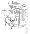
- FIG. 4 is an isometric view of a turbine assembly in accordance with one embodiment of the invention.
- FIG. 5 is an isometric view of the carrier in accordance with one embodiment of the invention.
- FIGS. 1 through 3 A turbocharger 20 in accordance with one embodiment of the invention is shown in FIGS. 1 through 3.
- the turbocharger includes a center housing 22 that contains bearings 24 for a rotary shaft 26 of the turbocharger.
- a compressor housing (not shown) is coupled to one side of the center housing.
- a compressor wheel 30 is mounted on one end of the shaft 26 and is disposed in the compressor housing.
- the compressor housing defines an inlet through which air is drawn into the compressor wheel 30, which compresses the air, and further defines a diffuser through which the compressed air is discharged from the compressor wheel into a volute surrounding the compressor wheel. From the volute, the air is delivered to the intake of an internal combustion engine (not shown).
- the turbocharger further comprises a turbine housing 38 coupled to the opposite side of the center housing 22.
- a turbine wheel 40 is mounted on the opposite end of the shaft 26 from the compressor wheel and is disposed in the turbine housing.
- the turbine housing defines a chamber 42 that surrounds the turbine wheel 40 and receives exhaust gas from the internal combustion engine. Exhaust gas is directed from the chamber 42 through a nozzle 43 (FIG. 4) into the turbine wheel 40, which expands the exhaust gas and is driven thereby so as to drive the compressor wheel.
- a heat shield 32 is disposed between the center housing 22 and turbine housing 38.
- the heat shields supports an array of circumferentially spaced vanes 34 that extend axially from the heat shield partway across the axial extent of the nozzle 43.
- the turbine housing 38 defines a generally cylindrical bore 44 whose diameter generally corresponds to a radially innermost extent of the chamber 42.
- the turbine wheel 40 resides in an upstream end of the bore 44 and the turbine wheel's rotational axis is substantially coaxial with the bore.
- upstream in this context refers to the direction of exhaust gas flow through the bore 44, as the exhaust gas in the chamber 42 flows into the turbine wheel 40 and is then turned to flow generally axially (left to right in FIG. 1) through the bore 44 to its downstream end.
- the turbocharger includes a sliding piston assembly 50 that resides in the bore 44 of the turbine housing.
- the piston assembly comprises a tubular carrier 52 whose outer diameter is slightly smaller than the diameter of the turbine housing bore 44 such that the carrier 52 can be slid axially into the bore 44 from its downstream end (i.e., slid right to left in FIG. 2).
- the tubular carrier is shown in isolation in FIG. 5.
- the bore 44 includes a radially inward step 46 that faces downstream and the carrier includes a radially outwardly projecting flange or protuberance 54 that abuts the step 46.
- a retainer clip or ring 56 is snapped into a groove 57 in the inner surface of the bore 44 behind the carrier 52 to retain the carrier in the turbine housing.
- the carrier is prevented from moving axially in the bore 44 by the step 46 and the retainer ring 56.
- the piston assembly 50 further comprises a piston 62 of tubular form.
- the piston is coaxially disposed within the central bore of the carrier 52 and is slidable relative to the carrier in the axial direction.
- the piston is axially slidable between a closed position as shown in FIG. 1 wherein the piston abuts the ends of the vanes 34, an open position as shown in FIG. 3 wherein the piston is spaced from the vanes by a relatively larger distance, and various partially open positions therebetween such as the position shown in FIG. 2 wherein the piston is spaced by smaller distances from the vanes.
- the closed position the size of the nozzle through which exhaust gas flows from the chamber 42 to the turbine wheel is a minimum and the exhaust gas is constrained to flow through the row of vanes 34.
- the nozzle flow area is a maximum and part of the gas flows through the vanes while the remainder flows through a vaneless annular opening adjacent the vanes.
- the carrier 52 has an axial split 58 (FIG. 5) extending the length of the carrier.
- the split enables the carrier to expand and contract in diameter in response to thermal effects or other causes.
- the carrier advantageously has an inner diameter only slightly greater than the outer diameter of the piston 62, such that a very small gap exists between the carrier and piston. Accordingly, leakage flow through the gap is minimized. Because the carrier can expand and contract in diameter, there is no need to make the gap large to facilitate assembly or to accommodate dimensional changes during operation. The ability of the carrier to expand also means that binding of the piston is avoided.
- the carrier 52 includes a plurality of apertures 60 through the side wall of the carrier.
- the apertures are axially elongated for purposes explained below.
- the apertures are spaced about the circumference of the carrier.
- the turbocharger also includes a piston actuating linkage comprising a fork-shaped swing arm 70.
- the swing arm has a pair of arms 72 whose distal ends extend through two of the apertures 60 and engage the piston 62 at diametrically opposite locations of the piston.
- the swing arm is disposed adjacent the outer surface of the carrier and resides in a portion of the bore 44 that has an enlarged diameter.
- the swing arm is pivotable about a transverse axis so as to cause the piston to be advanced axially within the carrier 52.
- FIG. 1 shows the piston in the closed position, wherein the distal ends of the arms 72 are positioned toward one end of the apertures 60.
- FIG. 3 shows the piston in the open position in which the arms are positioned toward the other end of the apertures.
- the apertures are axially elongated to allow the requisite degree of axial travel of the arms 72.
- the swing arm 70 is actuated by an actuator mechanism coupled to an actuator such as a vacuum chamber actuator or the like (
- the axially split carrier 52 allows the carrier to substantially conform to the outer diameter of the piston at all operating conditions, the carrier expanding or contracting in diameter along with the piston as temperature changes. Accordingly, the carrier reduces gas leakage by maintaining a minimal gap between the carrier and piston. Although some gas leakage can occur through the axial split when it opens up, but it is expected this leakage would be small. Gas leakage between the carrier and the turbine housing is minimized by the engagement between the lip or projection 54 and the corresponding step surface 46 of the turbine housing, and by the snap ring 56 that presses the projection 54 against the surface 46.
- a turbocharger having a sliding piston assembly comprising a tubular piston disposed in the bore of the turbine housing such that the piston is axially slidable relative to the turbine housing.
- the piston assembly further comprises a tubular carrier inserted axially into the bore of the turbine housing surrounding the piston and fixed against axial movement relative to the turbine housing, a radially outer surface of the carrier engaging an inner surface of the bore and a radially inner surface of the carrier being slidably engaged by a radially outer surface of the piston.
- the carrier defines an axial split extending a length of the carrier, and the carrier is resiliently flexible. Accordingly, the axial split allows the carrier to expand and contract in diameter.
Landscapes
- Engineering & Computer Science (AREA)
- Mechanical Engineering (AREA)
- General Engineering & Computer Science (AREA)
- Supercharger (AREA)
- Pistons, Piston Rings, And Cylinders (AREA)
Applications Claiming Priority (1)
| Application Number | Priority Date | Filing Date | Title |
|---|---|---|---|
| US11/289,214 US7338254B2 (en) | 2005-11-29 | 2005-11-29 | Turbocharger with sliding piston assembly |
Publications (2)
| Publication Number | Publication Date |
|---|---|
| EP1790829A2 true EP1790829A2 (de) | 2007-05-30 |
| EP1790829A3 EP1790829A3 (de) | 2012-07-04 |
Family
ID=37596155
Family Applications (1)
| Application Number | Title | Priority Date | Filing Date |
|---|---|---|---|
| EP06125038A Withdrawn EP1790829A3 (de) | 2005-11-29 | 2006-11-29 | Abgasturbolader mit Ringschieber |
Country Status (2)
| Country | Link |
|---|---|
| US (1) | US7338254B2 (de) |
| EP (1) | EP1790829A3 (de) |
Cited By (5)
| Publication number | Priority date | Publication date | Assignee | Title |
|---|---|---|---|---|
| EP2148043A3 (de) * | 2008-07-24 | 2013-06-26 | Honeywell International Inc. | Abgasturbolader variabler Geometrie mit Ringschieber und mit in der Bohrung des Turbinengehäuses montiertem Einsatz |
| WO2013156047A3 (de) * | 2012-04-19 | 2014-02-20 | Ihi Charging Systems International Gmbh | Turbine für einen abgasturbolader |
| EP2105583A3 (de) * | 2008-03-28 | 2014-05-14 | Honeywell International Inc. | Turbolader mit Gleitkolben und Schaufeln und Auslaufsperren |
| CN103842631A (zh) * | 2011-12-27 | 2014-06-04 | 三菱重工业株式会社 | 增压器用涡轮机以及增压器的组装方法 |
| EP3372801B1 (de) * | 2015-11-06 | 2019-10-23 | Calsonic Kansei Corporation | Turbinengehäuse |
Families Citing this family (10)
| Publication number | Priority date | Publication date | Assignee | Title |
|---|---|---|---|---|
| US7581394B2 (en) * | 2003-12-10 | 2009-09-01 | Honeywell International Inc. | Variable nozzle device for a turbocharger |
| US8047772B2 (en) * | 2005-03-30 | 2011-11-01 | Honeywell International Inc. | Variable geometry turbine for a turbocharger and method of controlling the turbine |
| JP4468286B2 (ja) * | 2005-10-21 | 2010-05-26 | 三菱重工業株式会社 | 排気ターボ式過給機 |
| EP1957757B1 (de) * | 2005-11-16 | 2013-02-13 | Honeywell International Inc. | Turbolader mit axialem Ringschiebereinsatz |
| EP1816317B1 (de) * | 2006-02-02 | 2013-06-12 | IHI Corporation | Turbolader mit variabler Geometrie |
| EP2037100B1 (de) * | 2006-06-21 | 2017-11-15 | IHI Corporation | Lagerstruktur für rotationsmaschine sowie verfahren zur herstellung einer lagerstruktur |
| DE102006052447A1 (de) * | 2006-11-07 | 2008-05-08 | BSH Bosch und Siemens Hausgeräte GmbH | Linearverdichter und Gasdrucklager dafür |
| JP2008215083A (ja) * | 2007-02-28 | 2008-09-18 | Mitsubishi Heavy Ind Ltd | 可変容量型排気ターボ過給機における可変ノズル機構部取付構造 |
| DE102007046458A1 (de) * | 2007-09-28 | 2009-04-02 | Daimler Ag | Abgasturbolader für eine Brennkraftmaschine |
| GB2461720B (en) * | 2008-07-10 | 2012-09-05 | Cummins Turbo Tech Ltd | A variable geometry turbine |
Family Cites Families (8)
| Publication number | Priority date | Publication date | Assignee | Title |
|---|---|---|---|---|
| US5214920A (en) * | 1990-11-27 | 1993-06-01 | Leavesley Malcolm G | Turbocharger apparatus |
| US6715288B1 (en) * | 1999-05-27 | 2004-04-06 | Borgwarner, Inc. | Controllable exhaust gas turbocharger with a double-fluted turbine housing |
| JP2003535248A (ja) * | 2000-01-14 | 2003-11-25 | ハネウェル ガレット エス アー | 空力表面と遮熱板を結合して有するスライディングブレードおよび不連結シャフトアクチュエータ装置を備えるターボチャージャ |
| EP1301689B1 (de) * | 2000-07-19 | 2006-09-20 | Honeywell Garrett SA | Turbokompressor mit axial verschiebbaren leitschaufeln wobei die geometrie in längsrichtung unterschiedlich ist |
| GB0121864D0 (en) * | 2001-09-10 | 2001-10-31 | Leavesley Malcolm G | Turbocharger apparatus |
| GB2392956A (en) * | 2002-09-12 | 2004-03-17 | Honeywell Uk Ltd | Controlling inlet to turbocharger turbine |
| GB0227473D0 (en) * | 2002-11-25 | 2002-12-31 | Leavesley Malcolm G | Variable turbocharger apparatus with bypass apertures |
| DE10328167A1 (de) * | 2003-06-24 | 2005-01-13 | Daimlerchrysler Ag | Turbinengehäuse für einen Abgasturbolader |
-
2005
- 2005-11-29 US US11/289,214 patent/US7338254B2/en not_active Expired - Fee Related
-
2006
- 2006-11-29 EP EP06125038A patent/EP1790829A3/de not_active Withdrawn
Cited By (8)
| Publication number | Priority date | Publication date | Assignee | Title |
|---|---|---|---|---|
| EP2105583A3 (de) * | 2008-03-28 | 2014-05-14 | Honeywell International Inc. | Turbolader mit Gleitkolben und Schaufeln und Auslaufsperren |
| EP2148043A3 (de) * | 2008-07-24 | 2013-06-26 | Honeywell International Inc. | Abgasturbolader variabler Geometrie mit Ringschieber und mit in der Bohrung des Turbinengehäuses montiertem Einsatz |
| CN103842631A (zh) * | 2011-12-27 | 2014-06-04 | 三菱重工业株式会社 | 增压器用涡轮机以及增压器的组装方法 |
| EP2799690A4 (de) * | 2011-12-27 | 2015-08-19 | Mitsubishi Heavy Ind Ltd | Turbine für auflader und verfahren zur montage des aufladers |
| CN103842631B (zh) * | 2011-12-27 | 2017-08-29 | 三菱重工业株式会社 | 增压器用涡轮机以及增压器的组装方法 |
| US9810225B2 (en) | 2011-12-27 | 2017-11-07 | Mitsubishi Heavy Industries, Ltd. | Turbine for turbocharger and method for assembling turbocharger |
| WO2013156047A3 (de) * | 2012-04-19 | 2014-02-20 | Ihi Charging Systems International Gmbh | Turbine für einen abgasturbolader |
| EP3372801B1 (de) * | 2015-11-06 | 2019-10-23 | Calsonic Kansei Corporation | Turbinengehäuse |
Also Published As
| Publication number | Publication date |
|---|---|
| US7338254B2 (en) | 2008-03-04 |
| US20070122268A1 (en) | 2007-05-31 |
| EP1790829A3 (de) | 2012-07-04 |
Similar Documents
| Publication | Publication Date | Title |
|---|---|---|
| US7338254B2 (en) | Turbocharger with sliding piston assembly | |
| EP2573363B1 (de) | Turbolader mit variabler Geometrie mit einer Schaufelabdichtungsanordnung | |
| US20080271449A1 (en) | Turbocharger with sliding piston, having overlapping fixed and moving vanes | |
| EP2594745B1 (de) | Anordnung mit verstellbaren Düsen für Turbolader mit Schaufelabdichtungsanordnung | |
| KR100289549B1 (ko) | 반경류형 배기 터보과급기 터빈 | |
| EP2105583B1 (de) | Turbolader mit Gleitkolben und Leitschaufeln mit Dichtungsdämmen | |
| US6158956A (en) | Actuating mechanism for sliding vane variable geometry turbine | |
| US20080031728A1 (en) | Vane assembly and method of assembling a vane assembly for a variable-nozzle turbocharger | |
| US20100196145A1 (en) | Turbine assembly for an exhaust gas-driven turbocharger having a variable nozzle | |
| JP2017515051A (ja) | 可変ジオメトリタービンアセンブリ | |
| US6928818B1 (en) | Actuation assembly for variable geometry turbochargers | |
| CN107725118A (zh) | 具有用于径向定位可变喷嘴盒体的器件的可变喷嘴涡轮机 | |
| US7186077B2 (en) | Compressor, particularly in an exhaust gas turbocharger for an internal combustion engine | |
| US7762067B2 (en) | Turbocharger with sliding piston assembly | |
| EP2148043A2 (de) | Abgasturbolader variabler Geometrie mit Ringschieber und mit in der Bohrung des Turbinengehäuses montiertem Einsatz | |
| US20170044925A1 (en) | Turbocharger turbine with variable nozzle | |
| US8197195B2 (en) | Turbocharger with stepped two-stage vane nozzle | |
| US7249930B2 (en) | Variable-nozzle turbocharger with integrated bypass | |
| US8112995B2 (en) | Turbocharger with variable turbine geometry | |
| US20090301082A1 (en) | Turbocharger having piston-type variable nozzle with integrated actuation system | |
| CN116867959A (zh) | 用于涡轮机的排放阀的密封装置 |
Legal Events
| Date | Code | Title | Description |
|---|---|---|---|
| PUAI | Public reference made under article 153(3) epc to a published international application that has entered the european phase |
Free format text: ORIGINAL CODE: 0009012 |
|
| AK | Designated contracting states |
Kind code of ref document: A2 Designated state(s): AT BE BG CH CY CZ DE DK EE ES FI FR GB GR HU IE IS IT LI LT LU LV MC NL PL PT RO SE SI SK TR |
|
| AX | Request for extension of the european patent |
Extension state: AL BA HR MK YU |
|
| PUAL | Search report despatched |
Free format text: ORIGINAL CODE: 0009013 |
|
| AK | Designated contracting states |
Kind code of ref document: A3 Designated state(s): AT BE BG CH CY CZ DE DK EE ES FI FR GB GR HU IE IS IT LI LT LU LV MC NL PL PT RO SE SI SK TR |
|
| AX | Request for extension of the european patent |
Extension state: AL BA HR MK RS |
|
| RIC1 | Information provided on ipc code assigned before grant |
Ipc: F01D 17/16 20060101ALI20120525BHEP Ipc: F02C 6/12 20060101ALI20120525BHEP Ipc: F01D 17/14 20060101AFI20120525BHEP |
|
| 17P | Request for examination filed |
Effective date: 20120621 |
|
| AKX | Designation fees paid |
Designated state(s): DE FR GB |
|
| STAA | Information on the status of an ep patent application or granted ep patent |
Free format text: STATUS: THE APPLICATION HAS BEEN WITHDRAWN |
|
| 18W | Application withdrawn |
Effective date: 20141022 |