EP1793083A2 - Gekühlte Turbinenschaufel mit verlängerter Lebensdauer - Google Patents
Gekühlte Turbinenschaufel mit verlängerter Lebensdauer Download PDFInfo
- Publication number
- EP1793083A2 EP1793083A2 EP06077151A EP06077151A EP1793083A2 EP 1793083 A2 EP1793083 A2 EP 1793083A2 EP 06077151 A EP06077151 A EP 06077151A EP 06077151 A EP06077151 A EP 06077151A EP 1793083 A2 EP1793083 A2 EP 1793083A2
- Authority
- EP
- European Patent Office
- Prior art keywords
- radial
- turbine blade
- channel
- cavity
- wall
- Prior art date
- Legal status (The legal status is an assumption and is not a legal conclusion. Google has not performed a legal analysis and makes no representation as to the accuracy of the status listed.)
- Granted
Links
Images

Classifications
-
- F—MECHANICAL ENGINEERING; LIGHTING; HEATING; WEAPONS; BLASTING
- F01—MACHINES OR ENGINES IN GENERAL; ENGINE PLANTS IN GENERAL; STEAM ENGINES
- F01D—NON-POSITIVE DISPLACEMENT MACHINES OR ENGINES, e.g. STEAM TURBINES
- F01D5/00—Blades; Blade-carrying members; Heating, heat-insulating, cooling or antivibration means on the blades or the members
- F01D5/12—Blades
- F01D5/14—Form or construction
- F01D5/18—Hollow blades, i.e. blades with cooling or heating channels or cavities; Heating, heat-insulating or cooling means on blades
- F01D5/186—Film cooling
-
- F—MECHANICAL ENGINEERING; LIGHTING; HEATING; WEAPONS; BLASTING
- F01—MACHINES OR ENGINES IN GENERAL; ENGINE PLANTS IN GENERAL; STEAM ENGINES
- F01D—NON-POSITIVE DISPLACEMENT MACHINES OR ENGINES, e.g. STEAM TURBINES
- F01D5/00—Blades; Blade-carrying members; Heating, heat-insulating, cooling or antivibration means on the blades or the members
- F01D5/12—Blades
- F01D5/14—Form or construction
- F01D5/18—Hollow blades, i.e. blades with cooling or heating channels or cavities; Heating, heat-insulating or cooling means on blades
-
- F—MECHANICAL ENGINEERING; LIGHTING; HEATING; WEAPONS; BLASTING
- F05—INDEXING SCHEMES RELATING TO ENGINES OR PUMPS IN VARIOUS SUBCLASSES OF CLASSES F01-F04
- F05D—INDEXING SCHEME FOR ASPECTS RELATING TO NON-POSITIVE-DISPLACEMENT MACHINES OR ENGINES, GAS-TURBINES OR JET-PROPULSION PLANTS
- F05D2260/00—Function
- F05D2260/20—Heat transfer, e.g. cooling
-
- F—MECHANICAL ENGINEERING; LIGHTING; HEATING; WEAPONS; BLASTING
- F05—INDEXING SCHEMES RELATING TO ENGINES OR PUMPS IN VARIOUS SUBCLASSES OF CLASSES F01-F04
- F05D—INDEXING SCHEME FOR ASPECTS RELATING TO NON-POSITIVE-DISPLACEMENT MACHINES OR ENGINES, GAS-TURBINES OR JET-PROPULSION PLANTS
- F05D2260/00—Function
- F05D2260/20—Heat transfer, e.g. cooling
- F05D2260/202—Heat transfer, e.g. cooling by film cooling
-
- F—MECHANICAL ENGINEERING; LIGHTING; HEATING; WEAPONS; BLASTING
- F05—INDEXING SCHEMES RELATING TO ENGINES OR PUMPS IN VARIOUS SUBCLASSES OF CLASSES F01-F04
- F05D—INDEXING SCHEME FOR ASPECTS RELATING TO NON-POSITIVE-DISPLACEMENT MACHINES OR ENGINES, GAS-TURBINES OR JET-PROPULSION PLANTS
- F05D2260/00—Function
- F05D2260/20—Heat transfer, e.g. cooling
- F05D2260/221—Improvement of heat transfer
- F05D2260/2214—Improvement of heat transfer by increasing the heat transfer surface
- F05D2260/22141—Improvement of heat transfer by increasing the heat transfer surface using fins or ribs
-
- Y—GENERAL TAGGING OF NEW TECHNOLOGICAL DEVELOPMENTS; GENERAL TAGGING OF CROSS-SECTIONAL TECHNOLOGIES SPANNING OVER SEVERAL SECTIONS OF THE IPC; TECHNICAL SUBJECTS COVERED BY FORMER USPC CROSS-REFERENCE ART COLLECTIONS [XRACs] AND DIGESTS
- Y02—TECHNOLOGIES OR APPLICATIONS FOR MITIGATION OR ADAPTATION AGAINST CLIMATE CHANGE
- Y02T—CLIMATE CHANGE MITIGATION TECHNOLOGIES RELATED TO TRANSPORTATION
- Y02T50/00—Aeronautics or air transport
- Y02T50/60—Efficient propulsion technologies, e.g. for aircraft
Definitions
- the present invention relates to the field of turbine blades, in particular a turbomachine turbine blade with improved cooling and lifetime.
- An aviation turbine engine typically comprises a compressor, a combustion chamber and a turbine.
- the role of the turbine is to ensure the rotational drive of the compressor by taking a portion of the pressure energy of the hot gases leaving the combustion chamber and converting it into mechanical energy.
- An axial turbine conventionally comprises at least one distributor, consisting of a vanes grid fixed with respect to the casing of the turbomachine, and at least one movable wheel, comprising a set of vanes capable of being rotated, placed behind the distributor.
- the turbine located downstream of the combustion chamber, is the organ of the turbomachine that works in the most severe conditions. It is particularly subject to significant thermal stresses generated by the hot gases at the chamber outlet.
- the resistance to the thermal stresses of the turbine constitutes the most important limitation for the operation of the turbomachine. This limitation sets the maximum fuel flow that can be injected into the combustion chamber of the turbomachine and the maximum thrust that can be obtained for a turbomachine.
- the thermal resistance of the turbine depends on the temperature tolerated by the blades. At each temperature corresponds a life of the turbine, this life decreasing when the temperature increases.
- Existing solutions for improving the thermal resistance of the turbine blades consist essentially of improving the materials constituting them and cooling them during operation.
- the cooling of the wall of a turbine blade is performed by exchanging calories between the hot gases and the air circulating inside the blade, more precisely by forced convection of a cooling air on the inner walls of dawn.
- the document EP1008724 illustrates, in Figure 6, an example of a turbine blade having a plurality of radial cavities. These radial cavities can communicate with each other by their ends to form a so-called serpentine cooling circuit.
- the cooling circuit 36 delimited by walls 34 and having an inlet 36A and a terminal end 36B, is composed of three radial cavities communicating by turning channels 37A and 37B.
- the radial cavities may also communicate with each other by means of channels that are substantially smaller than the turning channels.
- the narrowness of these channels makes it possible to project the cooling air under pressure so as to promote convective heat exchange.
- a trailing edge cavity 72 and a cavity 41B upstream thereof, separated by a wall 75 communicate with each other via channels 74 located in the wall 75.
- the flow of hot gases from the combustion chamber causes an unequal distribution of temperatures on the intrados and extrados of the turbine blades.
- the hot gases arrive directly on the intrados wall of the turbine blades.
- the underside of a turbine blade is subjected to temperatures greater than its extrados, which has the consequence of generating a gradient thermal between the walls of the intrados and the extrados harmful to the life of the dawn.
- the air is distributed very poorly in the first trailing edge cavity 4.
- the narrowness of the trailing edge cavity 4 and the distribution of air in a plane merging with the skeleton 11 cause a heat exchange on the inner surface 42 of the intrados wall 2 adjacent to the inner surface 43 of the extrados wall 3.
- This disadvantage is accentuated by the fact that the skeleton 11 at the level of the second cavity 5 is situated in the extension of the axes of the channels 8 .
- a turbine blade has a good service life if its two intrados 2 and extrados 3 walls have a nearby metal temperature, that is to say a low thermal gradient.
- the heat exchange of the hot gases outside a cavity is greater at the intrados 2 than the extrados 3.
- a turbine blade having a lower surface, an extrados wall, at least a first cavity radial radial trailing edge, at least a second radial cavity upstream of the trailing edge cavity, an inner wall separating the radial cavities and comprising at least one channel connecting the cavities to each other, said channel being oriented along an axis intersecting the inner surface of the intrados wall in the first radial trailing edge cavity.
- the object of the present invention is to optimize the distribution of cooling air in a turbine blade to improve the service life.
- said axis is inclined at an angle between 5 ° and 70 ° with respect to a tangent to a portion of a skeleton of the blade, said skeleton portion being located inside the channel.
- this angle ⁇ is between 5 ° and 35 °.
- the present invention applies both to a fixed turbine blade and to a turbine blade.
- the present invention also relates to a turbine comprising at least one such blade and a turbomachine comprising such a turbine.
- FIG. 1 represents a mobile blade 1 of a turbine having a lower wall 2, an extrados wall 3 and a plurality of radial cavities 4 and 5.
- radial cavity is meant a cavity disposed along a radius coming from the axis of rotation of the turbomachine when the blade is properly mounted on the turbomachine.
- a so-called radial axis is an axis that merges with such a radius.
- only two radial cavities 4 and 5, located downstream relative to the flow of air around the blade 1, are shown.
- first radial cavity 4 located in the direct vicinity of the trailing edge of the blade, called the trailing edge cavity and, on the other hand, a second radial cavity 5 adjacent to and located in upstream of the first radial cavity trailing edge 4.
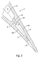
- first radial cavity 4 and 5 are separated by an inner wall 6 having a plurality of channels 8, as shown in Figure 2.
- the cooling of the second radial cavity 5 is provided by a supply of cooling air injected by the foot 10 of the blade 1.
- the cooling of the first radial trailing edge cavity 4 is provided by the same cooling air which passes through the channels 8. The cooling air is then expelled outside the blade 1 by outlet channels 9.
- the channels 8 of the inner wall 6, as well as the radial cavities 4 and 5, can be obtained according to a lost wax molding technique, well known to those skilled in the art.
- channels 8 have a section of oblong shape in a radial direction. Other forms of channel section 8 are possible.
- the axis 81 of a channel 8 that is to say the line perpendicular to the plane of the section and passing through the center of the section, defines the desired direction of the flow of the cooling air output of the channel 8.
- the axis of the channels 8 is perpendicular to a radial direction.
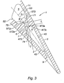
- FIG. 3 illustrates the solution proposed by the invention for improving the service life of the blades, which consists in producing at least one channel 7 oriented along an axis 71 intersecting the inner surface 42 of the intrados wall 2.
- This inclination of the axis 71 in the direction of the inner surface 42 of the intrados wall 2 advantageously allows to cool more intensely the intrados wall 2 than the extrados wall 3.
- the cooling air at the outlet of these channels 7 is indeed directly projected on the inner surface 42
- the thermal gradient observed in the prior art between the intrados wall 2 and the extrados wall 3 is therefore substantially attenuated, which contributes to improving the mechanical strength of the blade 1 and hence its duration. of life.
- each channel 7 is inclined at an angle ⁇ with respect to a tangent to a portion of the skeleton 11 of the blade 1, said skeleton portion 11 being located inside the channel 7, contrary to the axes 81 channels 8 of the prior art which are almost parallel to this tangent.
- the angle ⁇ is between 5 ° and 70 °, preferably 5 ° and 35 °, an angle of 25 ° providing satisfactory results.
- the narrowness of the channels 7 allows under the action of the pressure in the radial cavity 5 to project the cooling air so as to promote heat exchange by convection.
- the channels 7 are flared at their downstream ends 74 and upstream 75 respectively opening into the radial cavities 4 and 5. Because of these flares in the form of fillet to facilitate molding, the cooling air may be poorly projected on the inner surface 42 of the intrados wall 2 in the radial trailing edge cavity 4.
- a channel 7 For effective cooling by convection, a channel 7 must have a sufficient guide length L.
- the guide length is the maximum length of the channel having a substantially constant section. It is estimated that the guide length L is sufficient when the ratio of the guide length L to the guide width 1, that is to say the width of the section in a plane perpendicular to a radial axis is greater than 1.
- the guide length L must therefore be greater than the guide width I. Preferably, this ratio is greater than 1.5.
- This guide length L makes it possible to guarantee good convective cooling of the inner surface 42 of the intrados wall 2 in the first radial trailing edge cavity 4.
- the upstream end 75 of the channel 7 is adjacent to the inner surface 53 of the extrados wall 3 in the second radial cavity 5 and the downstream end 74 of the channel 7 is adjacent to the inner surface 42 of the intrados wall 2 in the first radial trailing edge cavity 4.
- the upstream end 75 of the channel 7 is connected at its outlet in the radial cavity 5, on the one hand, to the inner surface 53 by a fillet 573 with a large radius of curvature, and on the other hand, at the inner surface 52 successively by a rounding 572a and a fillet 572c with small radii of curvature, while the downstream end 74 of the channel 7 is connected at its output in the radial trailing edge cavity 4, d on the one hand, on the inner surface 42 by a fillet 472 with a large radius of curvature, and on the other hand, on the inner surface 43 successively by a rounded portion 473a and a fillet 473c with small radii of curvature.
- the roundings 572a and 473a are in the form of protuberances protruding from the intrados and extrados internal surfaces towards the skeleton 11.
- the surface on which opens the upstream end 75 of the channel 7 defines an angle ⁇ with the axis 71 of the channel 7 between 90 ° and 120 °. This arrangement facilitates the manufacture of the blade by molding and contributes to obtain a longer guide length L.
- the radial trailing edge cavity 4 may furthermore have disrupters on its internal surfaces 42 and 43.
- Disrupters are reliefs made on the internal surfaces of the blades to promote heat exchange.
- the disrupters can take the form of protruding rib or nipple.
- the channels 7 are distributed radially along the height of the inner wall 6.
Landscapes
- Engineering & Computer Science (AREA)
- Mechanical Engineering (AREA)
- General Engineering & Computer Science (AREA)
- Turbine Rotor Nozzle Sealing (AREA)
Applications Claiming Priority (1)
| Application Number | Priority Date | Filing Date | Title |
|---|---|---|---|
| FR0512297A FR2894281B1 (fr) | 2005-12-05 | 2005-12-05 | Aube de turbine a refroidissement et a duree de vie ameliores |
Publications (3)
| Publication Number | Publication Date |
|---|---|
| EP1793083A2 true EP1793083A2 (de) | 2007-06-06 |
| EP1793083A3 EP1793083A3 (de) | 2008-11-26 |
| EP1793083B1 EP1793083B1 (de) | 2009-10-14 |
Family
ID=36942335
Family Applications (1)
| Application Number | Title | Priority Date | Filing Date |
|---|---|---|---|
| EP06077151A Active EP1793083B1 (de) | 2005-12-05 | 2006-12-01 | Gekühlte Turbinenschaufel mit verlängerter Lebensdauer |
Country Status (5)
| Country | Link |
|---|---|
| US (1) | US7670112B2 (de) |
| EP (1) | EP1793083B1 (de) |
| CA (1) | CA2569563C (de) |
| DE (1) | DE602006009748D1 (de) |
| FR (1) | FR2894281B1 (de) |
Cited By (6)
| Publication number | Priority date | Publication date | Assignee | Title |
|---|---|---|---|---|
| EP2612994A1 (de) * | 2012-01-05 | 2013-07-10 | General Electric Company | System und Verfahren zum Kühlen von Turbinenschaufeln |
| WO2015065671A1 (en) * | 2013-10-31 | 2015-05-07 | Siemens Aktiengesellschaft | Gas turbine engine component comprising a trailing edge cooling using angled impingement on surface enhanced with cast chevron arrangements |
| EP2946079A4 (de) * | 2013-01-15 | 2016-06-22 | United Technologies Corp | Gasturbinenmotorkomponente mit quer abgewinkelten prallrippen |
| EP3051064B1 (de) | 2015-01-21 | 2017-09-13 | United Technologies Corporation | Innenkühlungshohlraum mit nockenstreifen |
| FR3094033A1 (fr) * | 2019-03-22 | 2020-09-25 | Safran Aircraft Engines | Aube de turbomachine equipee d’un circuit de refroidissement optimise |
| RU2814335C2 (ru) * | 2019-03-22 | 2024-02-28 | Сафран Эркрафт Энджинз | Лопатка газотурбинного двигателя, оснащенная оптимизированной системой охлаждения |
Families Citing this family (6)
| Publication number | Priority date | Publication date | Assignee | Title |
|---|---|---|---|---|
| US8002525B2 (en) * | 2007-11-16 | 2011-08-23 | Siemens Energy, Inc. | Turbine airfoil cooling system with recessed trailing edge cooling slot |
| US8348614B2 (en) * | 2008-07-14 | 2013-01-08 | United Technologies Corporation | Coolable airfoil trailing edge passage |
| FR3014115B1 (fr) | 2013-12-02 | 2017-04-28 | Office National Detudes Et De Rech Aerospatiales Onera | Procede et systeme de depot d'oxyde sur un composant poreux |
| FR3013996B1 (fr) | 2013-12-02 | 2017-04-28 | Office National Detudes Et De Rech Aerospatiales Onera | Procede de reparation locale de barrieres thermiques |
| US10641113B2 (en) * | 2015-04-08 | 2020-05-05 | United Technologies Corporation | Airfoils |
| US11753944B2 (en) | 2018-11-09 | 2023-09-12 | Raytheon Technologies Corporation | Airfoil with wall that tapers in thickness |
Family Cites Families (11)
| Publication number | Priority date | Publication date | Assignee | Title |
|---|---|---|---|---|
| GB2260166B (en) * | 1985-10-18 | 1993-06-30 | Rolls Royce | Cooled aerofoil blade or vane for a gas turbine engine |
| US4770608A (en) * | 1985-12-23 | 1988-09-13 | United Technologies Corporation | Film cooled vanes and turbines |
| US4767268A (en) | 1987-08-06 | 1988-08-30 | United Technologies Corporation | Triple pass cooled airfoil |
| US5720431A (en) | 1988-08-24 | 1998-02-24 | United Technologies Corporation | Cooled blades for a gas turbine engine |
| US5246340A (en) * | 1991-11-19 | 1993-09-21 | Allied-Signal Inc. | Internally cooled airfoil |
| US5356265A (en) | 1992-08-25 | 1994-10-18 | General Electric Company | Chordally bifurcated turbine blade |
| US6129515A (en) * | 1992-11-20 | 2000-10-10 | United Technologies Corporation | Turbine airfoil suction aided film cooling means |
| US6126396A (en) | 1998-12-09 | 2000-10-03 | General Electric Company | AFT flowing serpentine airfoil cooling circuit with side wall impingement cooling chambers |
| US6206638B1 (en) | 1999-02-12 | 2001-03-27 | General Electric Company | Low cost airfoil cooling circuit with sidewall impingement cooling chambers |
| US6368060B1 (en) * | 2000-05-23 | 2002-04-09 | General Electric Company | Shaped cooling hole for an airfoil |
| US6607356B2 (en) * | 2002-01-11 | 2003-08-19 | General Electric Company | Crossover cooled airfoil trailing edge |
-
2005
- 2005-12-05 FR FR0512297A patent/FR2894281B1/fr not_active Expired - Fee Related
-
2006
- 2006-11-30 CA CA2569563A patent/CA2569563C/fr active Active
- 2006-12-01 DE DE602006009748T patent/DE602006009748D1/de active Active
- 2006-12-01 EP EP06077151A patent/EP1793083B1/de active Active
- 2006-12-04 US US11/566,423 patent/US7670112B2/en active Active
Cited By (14)
| Publication number | Priority date | Publication date | Assignee | Title |
|---|---|---|---|---|
| EP2612994A1 (de) * | 2012-01-05 | 2013-07-10 | General Electric Company | System und Verfahren zum Kühlen von Turbinenschaufeln |
| US9051842B2 (en) | 2012-01-05 | 2015-06-09 | General Electric Company | System and method for cooling turbine blades |
| EP2946079A4 (de) * | 2013-01-15 | 2016-06-22 | United Technologies Corp | Gasturbinenmotorkomponente mit quer abgewinkelten prallrippen |
| WO2015065671A1 (en) * | 2013-10-31 | 2015-05-07 | Siemens Aktiengesellschaft | Gas turbine engine component comprising a trailing edge cooling using angled impingement on surface enhanced with cast chevron arrangements |
| US9039371B2 (en) | 2013-10-31 | 2015-05-26 | Siemens Aktiengesellschaft | Trailing edge cooling using angled impingement on surface enhanced with cast chevron arrangements |
| US10605094B2 (en) | 2015-01-21 | 2020-03-31 | United Technologies Corporation | Internal cooling cavity with trip strips |
| EP3051064B1 (de) | 2015-01-21 | 2017-09-13 | United Technologies Corporation | Innenkühlungshohlraum mit nockenstreifen |
| US10947854B2 (en) | 2015-01-21 | 2021-03-16 | Raytheon Technologies Corporation | Internal cooling cavity with trip strips |
| FR3094033A1 (fr) * | 2019-03-22 | 2020-09-25 | Safran Aircraft Engines | Aube de turbomachine equipee d’un circuit de refroidissement optimise |
| WO2020193913A1 (fr) | 2019-03-22 | 2020-10-01 | Safran Aircraft Engines | Aube de turbomachine equipee d'un circuit de refroidissement optimise |
| CN113574248A (zh) * | 2019-03-22 | 2021-10-29 | 赛峰飞机发动机公司 | 设置有优化的冷却回路的涡轮发动机叶片 |
| US11808167B2 (en) | 2019-03-22 | 2023-11-07 | Safran Aircraft Engines | Turbine engine blade provided with an optimized cooling circuit |
| RU2814335C2 (ru) * | 2019-03-22 | 2024-02-28 | Сафран Эркрафт Энджинз | Лопатка газотурбинного двигателя, оснащенная оптимизированной системой охлаждения |
| CN113574248B (zh) * | 2019-03-22 | 2025-01-07 | 赛峰飞机发动机公司 | 设置有优化的冷却回路的涡轮发动机叶片 |
Also Published As
| Publication number | Publication date |
|---|---|
| EP1793083B1 (de) | 2009-10-14 |
| FR2894281A1 (fr) | 2007-06-08 |
| DE602006009748D1 (de) | 2009-11-26 |
| CA2569563C (fr) | 2014-01-28 |
| FR2894281B1 (fr) | 2010-08-20 |
| US7670112B2 (en) | 2010-03-02 |
| US20070128036A1 (en) | 2007-06-07 |
| CA2569563A1 (fr) | 2007-06-05 |
| EP1793083A3 (de) | 2008-11-26 |
Similar Documents
| Publication | Publication Date | Title |
|---|---|---|
| FR3071008B1 (fr) | Aube directrice de sortie pour turbomachine, comprenant un passage de refroidissement de lubrifiant equipe d'une matrice de conduction thermique comprimee entre les parois d'intrados et d'extrados | |
| EP2088286B1 (de) | Schaufel, zugehöriger beschaufelter Rotor und Strömungsmaschine | |
| EP1413771B1 (de) | Gehäuse, Verdichter, Turbine und Triebwerk mit einem solchen Gehäuse | |
| FR3046811A1 (fr) | Aube directrice de sortie pour turbomachine d'aeronef, presentant une fonction amelioree de refroidissement de lubrifiant | |
| FR3049644A1 (fr) | Aube directrice de sortie pour turbomachine d'aeronef, presentant une fonction amelioree de refroidissement de lubrifiant a l'aide d'une matrice de conduction thermique logee dans un passage interieur de l'aube | |
| CA2478746C (fr) | Aube creuse de rotor pour la turbine d'un moteur a turbine a gaz | |
| EP1741875B1 (de) | Kühlkreislauf für eine Rotorschaufel einer Turbomaschine | |
| EP3464824B1 (de) | Turbinenschaufel mit einem kühlluftansaugabschnitt mit einem schraubenförmigen element zum verwirbeln der kühlluft | |
| WO2019224463A1 (fr) | Secteur angulaire d'aubage de turbomachine avec etancheite entre secteurs | |
| EP2895692B1 (de) | Gekühlte schaufel einer hochdruckturbine | |
| CA2925438C (fr) | Ensemble rotatif pour turbomachine | |
| WO2011135234A2 (fr) | Elément d'interface entre un pied d'une aube et un logement du pied d'aube d'un disque de turbine, rotor de turbine comprenant un élément d'interface | |
| EP1793083B1 (de) | Gekühlte Turbinenschaufel mit verlängerter Lebensdauer | |
| CA2608268A1 (fr) | Secteur d'anneau de turbine de turbomachine | |
| FR2966869A1 (fr) | Systeme de refroidissement des zones de plate-forme d'aubes rotatives de turbine | |
| EP3548706A1 (de) | Austrittsleitschaufel einer turbomaschine eines flugzeugs mit einem gebogenen schmierkanal mit verbessertem design | |
| FR2922597A1 (fr) | Aube refroidie de turbomachine | |
| FR3079605A1 (fr) | Echangeur thermique a plaques muni d'un bouclier de repartition de debit d'un fluide pour turbomoteur | |
| FR3029242A1 (fr) | Aube de turbomachine, comprenant des cloisons entrecroisees pour la circulation d'air en direction du bord de fuite | |
| EP3317495B1 (de) | Turbinenschaufel mit abflachungen an der hinterkante | |
| FR3081499A1 (fr) | Secteur angulaire d'aubage de turbomachine a etancheite perfectionnee | |
| FR3101107A1 (fr) | Aube pour une turbomachine d’aeronef | |
| FR2943380A1 (fr) | Aube de distributeur comprenant au moins une fente | |
| FR3111661A1 (fr) | Aube de turbine avec système de refroidissement | |
| FR3079868A1 (fr) | Lechette d'etancheite entre rotor et stator et turbine ainsi equipee |
Legal Events
| Date | Code | Title | Description |
|---|---|---|---|
| PUAI | Public reference made under article 153(3) epc to a published international application that has entered the european phase |
Free format text: ORIGINAL CODE: 0009012 |
|
| 17P | Request for examination filed |
Effective date: 20061218 |
|
| AK | Designated contracting states |
Kind code of ref document: A2 Designated state(s): AT BE BG CH CY CZ DE DK EE ES FI FR GB GR HU IE IS IT LI LT LU LV MC NL PL PT RO SE SI SK TR |
|
| AX | Request for extension of the european patent |
Extension state: AL BA HR MK YU |
|
| PUAL | Search report despatched |
Free format text: ORIGINAL CODE: 0009013 |
|
| AK | Designated contracting states |
Kind code of ref document: A3 Designated state(s): AT BE BG CH CY CZ DE DK EE ES FI FR GB GR HU IE IS IT LI LT LU LV MC NL PL PT RO SE SI SK TR |
|
| AX | Request for extension of the european patent |
Extension state: AL BA HR MK RS |
|
| 17Q | First examination report despatched |
Effective date: 20090422 |
|
| GRAP | Despatch of communication of intention to grant a patent |
Free format text: ORIGINAL CODE: EPIDOSNIGR1 |
|
| AKX | Designation fees paid |
Designated state(s): DE FR GB SE |
|
| GRAS | Grant fee paid |
Free format text: ORIGINAL CODE: EPIDOSNIGR3 |
|
| GRAA | (expected) grant |
Free format text: ORIGINAL CODE: 0009210 |
|
| AK | Designated contracting states |
Kind code of ref document: B1 Designated state(s): DE FR GB SE |
|
| REG | Reference to a national code |
Ref country code: GB Ref legal event code: FG4D Free format text: NOT ENGLISH |
|
| REF | Corresponds to: |
Ref document number: 602006009748 Country of ref document: DE Date of ref document: 20091126 Kind code of ref document: P |
|
| REG | Reference to a national code |
Ref country code: SE Ref legal event code: TRGR |
|
| PLBE | No opposition filed within time limit |
Free format text: ORIGINAL CODE: 0009261 |
|
| STAA | Information on the status of an ep patent application or granted ep patent |
Free format text: STATUS: NO OPPOSITION FILED WITHIN TIME LIMIT |
|
| 26N | No opposition filed |
Effective date: 20100715 |
|
| REG | Reference to a national code |
Ref country code: FR Ref legal event code: PLFP Year of fee payment: 10 |
|
| REG | Reference to a national code |
Ref country code: FR Ref legal event code: PLFP Year of fee payment: 11 |
|
| REG | Reference to a national code |
Ref country code: FR Ref legal event code: PLFP Year of fee payment: 12 |
|
| REG | Reference to a national code |
Ref country code: FR Ref legal event code: CD Owner name: SAFRAN AIRCRAFT ENGINES, FR Effective date: 20170707 |
|
| PGFP | Annual fee paid to national office [announced via postgrant information from national office to epo] |
Ref country code: GB Payment date: 20251229 Year of fee payment: 20 |
|
| PGFP | Annual fee paid to national office [announced via postgrant information from national office to epo] |
Ref country code: FR Payment date: 20251222 Year of fee payment: 20 |
|
| PGFP | Annual fee paid to national office [announced via postgrant information from national office to epo] |
Ref country code: SE Payment date: 20251217 Year of fee payment: 20 |
|
| PGFP | Annual fee paid to national office [announced via postgrant information from national office to epo] |
Ref country code: DE Payment date: 20251222 Year of fee payment: 20 |