EP1793152B1 - Dispositif de raccordement fluidique avec une assemblage de connecteur électrique - Google Patents
Dispositif de raccordement fluidique avec une assemblage de connecteur électrique Download PDFInfo
- Publication number
- EP1793152B1 EP1793152B1 EP06024817A EP06024817A EP1793152B1 EP 1793152 B1 EP1793152 B1 EP 1793152B1 EP 06024817 A EP06024817 A EP 06024817A EP 06024817 A EP06024817 A EP 06024817A EP 1793152 B1 EP1793152 B1 EP 1793152B1
- Authority
- EP
- European Patent Office
- Prior art keywords
- fluid
- coupling
- electrical
- coupling arrangement
- coupling part
- Prior art date
- Legal status (The legal status is an assumption and is not a legal conclusion. Google has not performed a legal analysis and makes no representation as to the accuracy of the status listed.)
- Revoked
Links
Images


Classifications
-
- H—ELECTRICITY
- H01—ELECTRIC ELEMENTS
- H01R—ELECTRICALLY-CONDUCTIVE CONNECTIONS; STRUCTURAL ASSOCIATIONS OF A PLURALITY OF MUTUALLY-INSULATED ELECTRICAL CONNECTING ELEMENTS; COUPLING DEVICES; CURRENT COLLECTORS
- H01R13/00—Details of coupling devices of the kinds covered by groups H01R12/70 or H01R24/00 - H01R33/00
- H01R13/005—Electrical coupling combined with fluidic coupling
-
- F—MECHANICAL ENGINEERING; LIGHTING; HEATING; WEAPONS; BLASTING
- F16—ENGINEERING ELEMENTS AND UNITS; GENERAL MEASURES FOR PRODUCING AND MAINTAINING EFFECTIVE FUNCTIONING OF MACHINES OR INSTALLATIONS; THERMAL INSULATION IN GENERAL
- F16L—PIPES; JOINTS OR FITTINGS FOR PIPES; SUPPORTS FOR PIPES, CABLES OR PROTECTIVE TUBING; MEANS FOR THERMAL INSULATION IN GENERAL
- F16L25/00—Construction or details of pipe joints not provided for in, or of interest apart from, groups F16L13/00 - F16L23/00
- F16L25/01—Construction or details of pipe joints not provided for in, or of interest apart from, groups F16L13/00 - F16L23/00 specially adapted for realising electrical conduction between the two pipe ends of the joint or between parts thereof
-
- F—MECHANICAL ENGINEERING; LIGHTING; HEATING; WEAPONS; BLASTING
- F16—ENGINEERING ELEMENTS AND UNITS; GENERAL MEASURES FOR PRODUCING AND MAINTAINING EFFECTIVE FUNCTIONING OF MACHINES OR INSTALLATIONS; THERMAL INSULATION IN GENERAL
- F16L—PIPES; JOINTS OR FITTINGS FOR PIPES; SUPPORTS FOR PIPES, CABLES OR PROTECTIVE TUBING; MEANS FOR THERMAL INSULATION IN GENERAL
- F16L53/00—Heating of pipes or pipe systems; Cooling of pipes or pipe systems
- F16L53/30—Heating of pipes or pipe systems
- F16L53/35—Ohmic-resistance heating
- F16L53/38—Ohmic-resistance heating using elongate electric heating elements, e.g. wires or ribbons
-
- F—MECHANICAL ENGINEERING; LIGHTING; HEATING; WEAPONS; BLASTING
- F01—MACHINES OR ENGINES IN GENERAL; ENGINE PLANTS IN GENERAL; STEAM ENGINES
- F01N—GAS-FLOW SILENCERS OR EXHAUST APPARATUS FOR MACHINES OR ENGINES IN GENERAL; GAS-FLOW SILENCERS OR EXHAUST APPARATUS FOR INTERNAL-COMBUSTION ENGINES
- F01N2610/00—Adding substances to exhaust gases
- F01N2610/02—Adding substances to exhaust gases the substance being ammonia or urea
-
- F—MECHANICAL ENGINEERING; LIGHTING; HEATING; WEAPONS; BLASTING
- F01—MACHINES OR ENGINES IN GENERAL; ENGINE PLANTS IN GENERAL; STEAM ENGINES
- F01N—GAS-FLOW SILENCERS OR EXHAUST APPARATUS FOR MACHINES OR ENGINES IN GENERAL; GAS-FLOW SILENCERS OR EXHAUST APPARATUS FOR INTERNAL-COMBUSTION ENGINES
- F01N2610/00—Adding substances to exhaust gases
- F01N2610/10—Adding substances to exhaust gases the substance being heated, e.g. by heating tank or supply line of the added substance
-
- F—MECHANICAL ENGINEERING; LIGHTING; HEATING; WEAPONS; BLASTING
- F01—MACHINES OR ENGINES IN GENERAL; ENGINE PLANTS IN GENERAL; STEAM ENGINES
- F01N—GAS-FLOW SILENCERS OR EXHAUST APPARATUS FOR MACHINES OR ENGINES IN GENERAL; GAS-FLOW SILENCERS OR EXHAUST APPARATUS FOR INTERNAL-COMBUSTION ENGINES
- F01N2610/00—Adding substances to exhaust gases
- F01N2610/14—Arrangements for the supply of substances, e.g. conduits
-
- H—ELECTRICITY
- H01—ELECTRIC ELEMENTS
- H01R—ELECTRICALLY-CONDUCTIVE CONNECTIONS; STRUCTURAL ASSOCIATIONS OF A PLURALITY OF MUTUALLY-INSULATED ELECTRICAL CONNECTING ELEMENTS; COUPLING DEVICES; CURRENT COLLECTORS
- H01R13/00—Details of coupling devices of the kinds covered by groups H01R12/70 or H01R24/00 - H01R33/00
- H01R13/62—Means for facilitating engagement or disengagement of coupling parts or for holding them in engagement
- H01R13/627—Snap or like fastening
- H01R13/6275—Latching arms not integral with the housing
Definitions
- the present invention relates to a fluid coupling assembly having at least a first coupling part for connecting a first fluid conducting element such as a fluid line and at least one second fluid carrying element in cooperation with at least one second coupling part, wherein a fluid between the first fluid carrying element and the at least one second fluid-carrying element flows through the fluid coupling assembly.
- the invention further relates to a fluid distribution system in a motor vehicle that uses a fluid coupling assembly according to the present invention.
- the US 4,550,958 refers to a rotatable connector for connecting a vacuum cleaner hose to the vacuum cleaner housing.
- the vacuum cleaner hose is wound with an electrical line, which serves for the electrical supply of an electrically operated brush. Therefore, the rotatable connector has a connector for contacting this line and is provided with corresponding mating contacts of the housing, which are connected to slip rings on the housing neck.
- the US 2002/058436 A1 refers to a connector for connecting hoses and pipes on the one hand and electrical lines on the other.
- the electrical line is but in no immediate connection with the hose, but is only performed parallel to this.
- the lines are not for heating the hoses are suitable, but serve to monitor whether the fluidic connections are properly closed.
- the US 6,030,244 discloses a connector system, on the one hand mechanically connects hose lines together and on the other hand has electrical connectors for contacting electrical lines.
- the electrical lines are routed parallel to the hose lines to be carried in parallel with the hose, for example in an electrically controlled pneumatic brake system, but do not serve the heating of the hose.
- the WO 97/34339 A refers to a connector system for connecting hose lines, in which electrical contacts are plugged together when closing the mechanical connection.
- the parallel to the hose lines extending electrical conductors serve a power or signal supply.
- the GB 2 056 611 A refers to a connector for connecting a vacuum cleaner hose, with the same time an electrical connection between a guided along the hose along the cable on the one hand and the motor housing on the other hand is made.
- a coupling piece is proposed, which is used to connect the hose to the motor housing.
- this document does not disclose the provision of a heating wire and in no way a rotatable electrical contact.
- the US 5,791,377 discloses an electrically heated hose line, for example for directing wiper water to a windshield wiper nozzle.
- the hose line disclosed in this document shows heating wires for heating the hose, these wires are not electrically contacted by means of a connector, but via slidable contact elements provided inside the end piece.
- an electrical connector and a fluidic coupling which establish a connection between a heatable hose and a hot glue gun.
- a plurality of electrical conductors are included in the sheath of the tube, the ends of which are provided with crimp terminals.
- An electrical connector 24 receives these crimp terminals and allows electrical connection to another electrical connector 25 which contacts the hot melt gun via a loose electrical lead.
- the object on which the present invention is based is to disclose a fluid coupling arrangement and a corresponding fluid distribution system which fluidly as well as electrically connects elements of a fluid conveyor chain in the simplest and safest way and allows safe fluid flow under all operating conditions.
- the present invention is based on the basic idea that the fluid coupling arrangement has at least one electrical connector arrangement for connecting at least one first electrical line to at least one second electrical line.
- the clutch assembly according to the invention is a stable and robust solution even under the thermally and mechanically demanding environmental conditions in the automotive field.
- Another advantage of the solution according to the invention is that each power consumer each correct supply voltage can be provided.
- the first coupling part and a connector of the at least one connector assembly are accommodated in a first electrically insulating housing.
- a first electrically insulating housing Such an integrated solution makes it possible, for example, for heated hoses to be provided with prefabricated combined electrical and fluidic connections.
- the second coupling part and an associated mating connector of the at least one connector assembly are received in a second electrically insulating housing and that the first and second housing are plugged together to make the fluidic and the electrical connection, then the contacting of both fluidic as well as electrical Components in one step feasible.
- a holding device for mechanically securing the two coupling parts together in the assembled state can be provided.
- this holding device may be formed by at least one latching arm, which is arranged on one of the two coupling parts and can be latched with a latching projection arranged on the other coupling part.
- this holding device may be formed by at least one latching arm, which is arranged on one of the two coupling parts and can be latched with a latching projection arranged on the other coupling part.
- other known holding and locking devices such as a screw and the like for securing the two coupling parts can be used together.
- the first coupling part may also be designed, for example, as a fitting in the form of a through-coupling piece (I-piece), an elbow (L-piece) or a branch piece, which is also referred to as a T-piece. be executed.
- branches are possible for more than three connections.
- the fluid distribution system is simplified significantly, if the required distribution and power transmission need not be carried out in the form of loose wiring outside the fluid system, but is realized as an integrated clutch arrangement.
- a hose connection element for the first fluid line is formed on the first coupling part, which electrically contacts an electrical line arranged on the first fluid line and connects to the connector of the at least one connector arrangement.
- a heating wire of an electrically heated hose is contacted via the electrical connector of the fluid coupling arrangement according to the invention.
- the first coupling part can be rotatably arranged on the first fluid line and the at least one first electrical line can have an axially revolving around the fluid line slip ring of contact elements of a Connector is contacted at least one connector assembly. In this way it can also be prevented that the electrical contact is interrupted by mechanical stress of the contacting of the electrical line during installation or operation of the motor vehicle.
- the first coupling part and / or the second coupling part can be made electrically heated. In this way it can be ensured that the entire fluid distribution system remains ice-free.
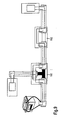
- Fig. 1 shows a fluid distribution system 100, as can be used in a motor vehicle, in a schematic representation.
- heatable components 102, 104 are supplied or flowed through fluid lines 106 with a fluid.
- the fluid can be either a liquid or a gas, for example water for windscreen cleaning or an aqueous urea solution, as used to reduce the nitrogen oxides in the SCR process.
- SCR Selective Catalytic Reduction
- SCR Selective Catalytic Reduction
- a reducing agent As a reducing agent, steam or gaseous ammonia is often used, which is generated by evaporation, subsequent thermolysis and hydrolysis of urea or a urea solution and introduced into the exhaust gas stream. Such a urea solution must then be transported along in appropriate tanks via the fluid conveyor chain and fed to the catalyst as a consumer. Furthermore, as a fluid, a gas, such as the blow-by gas in an internal combustion engine, are considered.
- the fluid lines 106 are electrically heated. , The connections of this electrical heating are symbolized by the electrical lines 108. As in Fig. 1 schematically illustrated, the connection between two heated fluid lines via a configured as a passage connector fluid coupling assembly 110 takes place.
- the fluid coupling arrangement 110 has a first coupling part 112 and a second coupling part 114. These two coupling parts cooperate to connect a first fluid line 116 to a second fluid line 118. Between the two fluid lines, the fluid flows in the connected state. Furthermore, the fluid coupling assembly 110 has an electrical connector assembly 120, by means of which the electrical leads 122, 124 and 126, 128 can be interconnected. An energy source 130 supplies the assembly with electrical energy needed, for example, to heat the tubes. In this case, the battery 130 shown can only be seen as an exemplary solution. The power supply can also be provided with suitable switching elements and fuses or be controlled by the engine electronics.
- Fig. 2 shows in a perspective view of the fluid coupling assembly 110 from Fig. 1 according to a possible embodiment.
- two fluid line pieces 116, 118 which are connected to each other via the fluid coupling assembly 110 according to a first embodiment, and a first coupling part 112 which is ready to be connected to either a further line piece or for example to the connection of a pump.
- an electrical connector arrangement 120 consisting of a plug connector 132 and a mating connector 134, is additionally provided on the fluid coupling arrangement 110 in order to be able to establish an electrical connection simultaneously with the fluidic coupling.
- Both the connector 132 and the mating connector 134 are connected to electrical lines inside the respective first and second coupling parts 112, 114, which are guided along the fluid lines 116, 118 (not shown in the figure).
- Two latching arms 136 which are integrally formed on the coupling part 112, cooperate with a latching projection 138, which is provided on the coupling part 114.
- the first coupling part 112 associated connector 132 is provided with connector pins 140, and the mating connector 134 is designed accordingly as a female connector.
- the mating connector 134 is designed accordingly as a female connector.
- any number and configuration of connector pins can be used in the connector 120.
- Common sealing devices 142 are disposed on the first coupling part 112 to prevent leakage of the fluid to the fluid coupling assembly 110. Furthermore, of course, the connector 120 may be sealed by professional measures against ingress of moisture.
- latching arms 136 have actuators 144, by means of which the latching connection can be easily solved when the fluid coupling is to be separated.
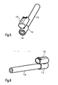
- FIGS. 3 and 4 Another embodiment of a first coupling part 112, as mounted on a fluid line 116, is shown in FIGS FIGS. 3 and 4 shown.
- the latching device is here on the connector 132.
- the associated latching arm and the connector 134 are not shown.
- This embodiment has the advantage that, in particular, the vibration-sensitive electrical connection is secured, while the firmly pressed fluid connection remains fixed in the axial direction without additional securing.
- a further advantageous embodiment of a first coupling part 112 is explained with a molded-on connector 132 thereon.
- the plug face of the connector 132 from the fluid entry port 146 turned away.
- This solution has the advantage that an electrical heating device integrated in the hose 116 can be connected to the plug connector 132 and can be electrically contacted by means of a loose mating plug connector 134, not shown here.
- the plug pins 140 are electrically connected to the slip rings 148, 150 via resilient contacts 154. Seals 156, 158 prevent the ingress of moisture into the electrical connector.
- FIG. 8 A further advantageous embodiment of the fluid coupling arrangement 110 according to the invention is shown in FIG. 8 shown.
- the power supply is located at one end of the fluid distribution system.
- the connector 120 may additionally have a supply plug 121 for connecting a supply voltage.
- a fluid distribution system for use in a motor vehicle may require the most diverse forms of a fluid coupling arrangement.
- a first coupling part can be provided, which realizes the shape of a T-piece and which in each case is contacted fluidically and electrically in accordance with the principles according to the invention.
- One such branch piece or tee is in Fig. 9 provided with the reference numeral 160.
- any other type of fittings can be realized using the principles of the invention: for example, a through-coupling piece (I-piece) 162 or an elbow (L-piece), which is not shown here.
- a T-shaped branching of the branching piece 160 instead of the T-shaped branching of the branching piece 160, a Y-shaped channel structure may also be provided.
- branches for more than three connections are possible.
- the individual elements of the fluid coupling assembly may be made heatable to prevent ice accumulation throughout the fluid distribution system.
Landscapes
- Engineering & Computer Science (AREA)
- General Engineering & Computer Science (AREA)
- Mechanical Engineering (AREA)
- Pipe Accessories (AREA)
Claims (9)
- Dispositif de raccordement fluidique pour gaz ou liquides comprenant au moins une première pièce de raccordement (112) et un premier élément conducteur de fluide (116), dans lequel la première pièce de raccordement (112) relie le premier élément conducteur de fluide (116) et au moins un deuxième élément conducteur de fluide (118) du dispositif de raccordement fluidique en conjonction avec au moins une deuxième pièce de raccordement (114) du dispositif de raccordement fluidique, dans lequel un fluide peut circuler à travers le dispositif de raccordement fluidique (110) entre le premier élément conducteur de fluide et l'au moins un deuxième élément conducteur de fluide,
étant entendu que le dispositif de raccordement fluidique comprend également au moins un assemblage de connecteur électrique (120) qui relie au moins une première ligne électrique (122, 124) du dispositif de raccordement fluidique à au moins une deuxième ligne électrique (126, 128) du dispositif de raccordement fluidique ;
au moins l'un des éléments conducteurs de fluide (116) étant un tuyau chauffé par un fil de chauffe du tuyau et l'au moins une première ligne électrique étant reliée au fil de chauffe ; étant entendu que
la première pièce de raccordement (112) ainsi qu'un connecteur (132) de l'au moins un assemblage de connecteur électrique étant contenus dans un premier logement isolant électriquement du dispositif de raccordement fluidique ;
caractérisé en ce que la deuxième pièce de raccordement (114) ainsi qu'un connecteur inverse (134) de l'au moins un assemblage de connecteur électrique sont contenus dans un deuxième logement isolant électriquement du dispositif de raccordement fluidique, étant entendu que les premier et deuxième logements peuvent être assemblés pour réaliser la liaison fluidique et électrique. - Dispositif de raccordement fluidique selon la revendication 1, comprenant également au moins un dispositif de retenue (136, 138) pour sécuriser mécaniquement les deux pièces de raccordement l'une avec l'autre dans une position assemblée.
- Dispositif de raccordement fluidique selon la revendication 2, dans lequel le dispositif de retenue est constitué par au moins un bras d'arrêt (136) qui est agencé sur l'une des deux pièces de raccordement et qui peut être enclenché avec une saillie d'arrêt (138) agencée sur l'autre pièce de raccordement.
- Dispositif de raccordement fluidique selon au moins l'une des revendications précédentes, dans lequel la première pièce de raccordement (112) est réalisée comme un raccord sous la forme d'une pièce de raccordement, d'une pièce coudée, d'une pièce d'embranchement ou d'un distributeur multiple.
- Dispositif de raccordement fluidique selon au moins l'une des revendications précédentes, dans lequel est formé, au moins sur la première pièce de raccordement (112), un élément de jonction de tuyau qui établit un contact électrique avec une ligne électrique agencée sur la première conduite de fluide et la relie à un connecteur (132) de l'au moins un assemblage de connecteur.
- Dispositif de raccordement fluidique selon au moins l'une des revendications précédentes, dans lequel au moins la première pièce de raccordement est agencée sur la première conduite de fluide de façon à pouvoir tourner et l'au moins une première ligne électrique présente une bague glissante encerclant la conduite de fluide de façon axiale, avec laquelle un contact est établi par des éléments de contact d'un connecteur de l'au moins un assemblage de connecteur.
- Dispositif de raccordement fluidique selon au moins l'une des revendications précédentes, dans lequel la première pièce de raccordement et/ou la deuxième pièce de raccordement sont réalisées de façon à pouvoir être chauffées électriquement.
- Dispositif de raccordement fluidique selon au moins l'une des revendications précédentes, qui est adapté pour distribuer un fluide sous forme liquide ou gazeuse.
- Système de distribution de fluide, de préférence pour l'utilisation dans un véhicule automobile, comprenant un dispositif de raccordement fluidique selon au moins l'une des revendications précédentes.
Applications Claiming Priority (1)
| Application Number | Priority Date | Filing Date | Title |
|---|---|---|---|
| DE102005057780A DE102005057780A1 (de) | 2005-12-02 | 2005-12-02 | Fluidkupplungsanordnung mit elektrischer Steckverbinderanordnung |
Publications (2)
| Publication Number | Publication Date |
|---|---|
| EP1793152A1 EP1793152A1 (fr) | 2007-06-06 |
| EP1793152B1 true EP1793152B1 (fr) | 2013-01-09 |
Family
ID=37876333
Family Applications (1)
| Application Number | Title | Priority Date | Filing Date |
|---|---|---|---|
| EP06024817A Revoked EP1793152B1 (fr) | 2005-12-02 | 2006-11-30 | Dispositif de raccordement fluidique avec une assemblage de connecteur électrique |
Country Status (2)
| Country | Link |
|---|---|
| EP (1) | EP1793152B1 (fr) |
| DE (1) | DE102005057780A1 (fr) |
Families Citing this family (17)
| Publication number | Priority date | Publication date | Assignee | Title |
|---|---|---|---|---|
| GB0918042D0 (en) | 2009-10-15 | 2009-12-02 | Delphi Tech Inc | Connector assembly and method of manufacturing same |
| DE102010019777B4 (de) | 2010-05-07 | 2019-08-22 | Airbus Operations Gmbh | Luftfahrzeug mit einem Fluidleitungssystem |
| DE102010020844A1 (de) * | 2010-05-18 | 2011-11-24 | Dbk David + Baader Gmbh | Verfahren zum Steuern einer Blowby-Funktion und Blowby-Einrichtung |
| DE102010030060A1 (de) * | 2010-06-15 | 2011-12-15 | Robert Bosch Gmbh | Steckverbindungssystem, Abgasnachbehandlungsvorrichtung |
| DE102010051550A1 (de) * | 2010-11-18 | 2012-05-24 | Voss Automotive Gmbh | Konfektionierte elektrisch beheizbare Medienleitung sowie Verfahren zum Herstellen einer solchen Medienleitung |
| DE102010053737A1 (de) * | 2010-12-08 | 2012-06-14 | Voss Automotive Gmbh | Beheizbare Fluidleitung, deren Verwendung sowie Verfahren zu ihrer Herstellung |
| DE102010053736B4 (de) | 2010-12-08 | 2018-03-29 | Voss Automotive Gmbh | Verbindungsanordnung für beheizbare Fluidleitungen |
| US11255476B2 (en) * | 2015-10-29 | 2022-02-22 | Wagner Spray Tech Corporation | Internally heated modular fluid delivery system |
| JP2017165265A (ja) * | 2016-03-16 | 2017-09-21 | 株式会社デンソー | 車両用衝突検知装置 |
| DE102016212118A1 (de) * | 2016-07-04 | 2018-01-04 | Mahle International Gmbh | Fluidkopplungseinrichtung, insbesondere für eine Kurbelgehäuseentlüftungseinrichtung |
| DE102016220594A1 (de) * | 2016-10-20 | 2018-04-26 | Contitech Schlauch Gmbh | Verteilerstück für beheizbare Fluidleitungen |
| DE102018103571A1 (de) * | 2018-02-16 | 2019-08-22 | Voss Automotive Gmbh | Verbindungsanordnung zum Verbinden von beheizbaren Fluidleitungen |
| WO2020079247A1 (fr) * | 2018-10-19 | 2020-04-23 | Eugen Forschner Gmbh | Dispositif d'assemblage |
| DE102018126886A1 (de) * | 2018-10-19 | 2020-04-23 | Eugen Forschner Gmbh | Verbindungsanordnung |
| CN109506066A (zh) * | 2018-12-20 | 2019-03-22 | 科莱斯(天津)电热科技有限公司 | 一种液体输送管道用感应加热电缆跨接装置 |
| WO2023242066A1 (fr) * | 2022-06-17 | 2023-12-21 | Stäubli Electrical Connectors Ag | Ensemble conducteur |
| FR3142084A1 (fr) * | 2022-11-17 | 2024-05-24 | Lpg Systems | Dispositif de raccordement pour une tête de massage |
Citations (1)
| Publication number | Priority date | Publication date | Assignee | Title |
|---|---|---|---|---|
| EP0187943A2 (fr) * | 1985-01-14 | 1986-07-23 | Nordson Corporation | Connecteur électrique entre une unité tuyau souple pour la fusion à chaud et un pistolet |
Family Cites Families (5)
| Publication number | Priority date | Publication date | Assignee | Title |
|---|---|---|---|---|
| GB2056611B (en) | 1979-08-16 | 1984-01-25 | Dayco Corp | Vacuum cleaner hose assembly and method of making same |
| US4550958A (en) * | 1984-09-17 | 1985-11-05 | Whirlpool Corporation | Electrical hose swivel connector for canister vacuum cleaner |
| AU2079397A (en) | 1996-03-15 | 1997-10-01 | Biw Connector Systems, Inc. | Improved connectors and methods |
| US5791377A (en) | 1996-07-08 | 1998-08-11 | Yazaki Corporation | Electrically heated conduit |
| US6464520B2 (en) * | 2000-11-16 | 2002-10-15 | Sumitomo Wiring Systems, Ltd. | Connector |
-
2005
- 2005-12-02 DE DE102005057780A patent/DE102005057780A1/de not_active Withdrawn
-
2006
- 2006-11-30 EP EP06024817A patent/EP1793152B1/fr not_active Revoked
Patent Citations (1)
| Publication number | Priority date | Publication date | Assignee | Title |
|---|---|---|---|---|
| EP0187943A2 (fr) * | 1985-01-14 | 1986-07-23 | Nordson Corporation | Connecteur électrique entre une unité tuyau souple pour la fusion à chaud et un pistolet |
Also Published As
| Publication number | Publication date |
|---|---|
| DE102005057780A1 (de) | 2007-06-06 |
| EP1793152A1 (fr) | 2007-06-06 |
Similar Documents
| Publication | Publication Date | Title |
|---|---|---|
| EP1793152B1 (fr) | Dispositif de raccordement fluidique avec une assemblage de connecteur électrique | |
| EP2220419B1 (fr) | Conduit chauffable pour fluides | |
| EP2010768B1 (fr) | Système de conduites flexibles chauffable d'installations de retraitement des gaz d'échappement de moteurs à combustion interne | |
| EP3008371B1 (fr) | Raccord de conduites et jeu de conduites pour milieux fluidiques | |
| EP2655950B1 (fr) | Conduite assemblée pour agents fluidiques et utilisation de ladite conduite dans un système catalyseur scr | |
| EP2167860A2 (fr) | Dispositif de raccord pour des tuyaux qui conduisent des milieux et qui peuvent être chauffés électriquement | |
| EP1070642A2 (fr) | Dispositif de chauffage pour lave-glace | |
| EP3869622A1 (fr) | Prise de recharge pour un véhicule électrique | |
| DE102008006323B4 (de) | Reduktionsmittelversorgungssystem für einen Abgasreinigungskatalysator eines Verbrennungsmotors und Steckverbindung zum Anschließen von beheizbaren Flüssigkeitsleitungen | |
| EP2652382B1 (fr) | Dispositif de raccordement pouvant être chauffé pour tuyaux conduisant des fluides pouvant être chauffés électriquement | |
| EP3538748B1 (fr) | Faisceau de conduites permettant le guidage thermo-régulé d'un agent réducteur pour le post-traitement des gaz d'échappement d'un moteur à combustion interne | |
| DE102011053260B4 (de) | Schnellkupplung zur Verbindung medienführender Leitungen | |
| DE102016113493A1 (de) | Leitungsverbinder und Verfahren zum Herstellen eines Leitungsverbinders | |
| WO2002038426A1 (fr) | Dispositif de rechauffement d'un liquide dans un systeme de conduite | |
| DE102007016789B4 (de) | Beheizbares Anschlussstück für eine Fluidleitung | |
| DE102009038092B3 (de) | Buchsenkontaktelement | |
| WO2011157517A1 (fr) | Système d'assemblage par enfichage, dispositif de recyclage de gaz d'échappement | |
| DE10212413B4 (de) | Waschwasserschlauch und Steckverbinder | |
| EP3211723B1 (fr) | Connecteur avec cable multi-brins | |
| DE102014004134A1 (de) | Beheizbare Leitung | |
| EP3752762B1 (fr) | Ensemble de liaison servant à relier des conduits pour fluide pouvant être chauffés | |
| EP0896902B1 (fr) | Element de véhicule, en particulier une tête de cylindre d'une machine à combustion | |
| EP1986281B1 (fr) | Procédé de fabrication d'une liaison électrique conductrice | |
| DE102016000192B3 (de) | Beheizbare Medienleitung | |
| EP1126177B1 (fr) | Interface électro-hydraulique |
Legal Events
| Date | Code | Title | Description |
|---|---|---|---|
| PUAI | Public reference made under article 153(3) epc to a published international application that has entered the european phase |
Free format text: ORIGINAL CODE: 0009012 |
|
| AK | Designated contracting states |
Kind code of ref document: A1 Designated state(s): AT BE BG CH CY CZ DE DK EE ES FI FR GB GR HU IE IS IT LI LT LU LV MC NL PL PT RO SE SI SK TR |
|
| AX | Request for extension of the european patent |
Extension state: AL BA HR MK YU |
|
| 17P | Request for examination filed |
Effective date: 20071205 |
|
| AKX | Designation fees paid |
Designated state(s): AT BE BG CH CY CZ DE DK EE ES FI FR GB GR HU IE IS IT LI LT LU LV MC NL PL PT RO SE SI SK TR |
|
| 17Q | First examination report despatched |
Effective date: 20081007 |
|
| GRAP | Despatch of communication of intention to grant a patent |
Free format text: ORIGINAL CODE: EPIDOSNIGR1 |
|
| GRAS | Grant fee paid |
Free format text: ORIGINAL CODE: EPIDOSNIGR3 |
|
| GRAA | (expected) grant |
Free format text: ORIGINAL CODE: 0009210 |
|
| AK | Designated contracting states |
Kind code of ref document: B1 Designated state(s): AT BE BG CH CY CZ DE DK EE ES FI FR GB GR HU IE IS IT LI LT LU LV MC NL PL PT RO SE SI SK TR |
|
| REG | Reference to a national code |
Ref country code: GB Ref legal event code: FG4D Free format text: NOT ENGLISH |
|
| REG | Reference to a national code |
Ref country code: CH Ref legal event code: EP Ref country code: AT Ref legal event code: REF Ref document number: 592964 Country of ref document: AT Kind code of ref document: T Effective date: 20130115 |
|
| REG | Reference to a national code |
Ref country code: IE Ref legal event code: FG4D Free format text: LANGUAGE OF EP DOCUMENT: GERMAN |
|
| REG | Reference to a national code |
Ref country code: DE Ref legal event code: R096 Ref document number: 502006012400 Country of ref document: DE Effective date: 20130307 |
|
| PG25 | Lapsed in a contracting state [announced via postgrant information from national office to epo] |
Ref country code: SI Free format text: LAPSE BECAUSE OF FAILURE TO SUBMIT A TRANSLATION OF THE DESCRIPTION OR TO PAY THE FEE WITHIN THE PRESCRIBED TIME-LIMIT Effective date: 20130109 |
|
| REG | Reference to a national code |
Ref country code: NL Ref legal event code: VDEP Effective date: 20130109 |
|
| REG | Reference to a national code |
Ref country code: LT Ref legal event code: MG4D |
|
| RAP2 | Party data changed (patent owner data changed or rights of a patent transferred) |
Owner name: DBK DAVID + BAADER GMBH |
|
| PG25 | Lapsed in a contracting state [announced via postgrant information from national office to epo] |
Ref country code: ES Free format text: LAPSE BECAUSE OF FAILURE TO SUBMIT A TRANSLATION OF THE DESCRIPTION OR TO PAY THE FEE WITHIN THE PRESCRIBED TIME-LIMIT Effective date: 20130420 Ref country code: IS Free format text: LAPSE BECAUSE OF FAILURE TO SUBMIT A TRANSLATION OF THE DESCRIPTION OR TO PAY THE FEE WITHIN THE PRESCRIBED TIME-LIMIT Effective date: 20130509 Ref country code: BG Free format text: LAPSE BECAUSE OF FAILURE TO SUBMIT A TRANSLATION OF THE DESCRIPTION OR TO PAY THE FEE WITHIN THE PRESCRIBED TIME-LIMIT Effective date: 20130409 Ref country code: SE Free format text: LAPSE BECAUSE OF FAILURE TO SUBMIT A TRANSLATION OF THE DESCRIPTION OR TO PAY THE FEE WITHIN THE PRESCRIBED TIME-LIMIT Effective date: 20130109 Ref country code: LT Free format text: LAPSE BECAUSE OF FAILURE TO SUBMIT A TRANSLATION OF THE DESCRIPTION OR TO PAY THE FEE WITHIN THE PRESCRIBED TIME-LIMIT Effective date: 20130109 |
|
| REG | Reference to a national code |
Ref country code: DE Ref legal event code: R082 Ref document number: 502006012400 Country of ref document: DE Representative=s name: WINTER, BRANDL, FUERNISS, HUEBNER, ROESS, KAIS, DE |
|
| PG25 | Lapsed in a contracting state [announced via postgrant information from national office to epo] |
Ref country code: NL Free format text: LAPSE BECAUSE OF FAILURE TO SUBMIT A TRANSLATION OF THE DESCRIPTION OR TO PAY THE FEE WITHIN THE PRESCRIBED TIME-LIMIT Effective date: 20130109 Ref country code: FI Free format text: LAPSE BECAUSE OF FAILURE TO SUBMIT A TRANSLATION OF THE DESCRIPTION OR TO PAY THE FEE WITHIN THE PRESCRIBED TIME-LIMIT Effective date: 20130109 Ref country code: LV Free format text: LAPSE BECAUSE OF FAILURE TO SUBMIT A TRANSLATION OF THE DESCRIPTION OR TO PAY THE FEE WITHIN THE PRESCRIBED TIME-LIMIT Effective date: 20130109 Ref country code: GR Free format text: LAPSE BECAUSE OF FAILURE TO SUBMIT A TRANSLATION OF THE DESCRIPTION OR TO PAY THE FEE WITHIN THE PRESCRIBED TIME-LIMIT Effective date: 20130410 Ref country code: PT Free format text: LAPSE BECAUSE OF FAILURE TO SUBMIT A TRANSLATION OF THE DESCRIPTION OR TO PAY THE FEE WITHIN THE PRESCRIBED TIME-LIMIT Effective date: 20130509 Ref country code: PL Free format text: LAPSE BECAUSE OF FAILURE TO SUBMIT A TRANSLATION OF THE DESCRIPTION OR TO PAY THE FEE WITHIN THE PRESCRIBED TIME-LIMIT Effective date: 20130109 |
|
| REG | Reference to a national code |
Ref country code: DE Ref legal event code: R082 Ref document number: 502006012400 Country of ref document: DE Representative=s name: WINTER, BRANDL, FUERNISS, HUEBNER, ROESS, KAIS, DE Effective date: 20130807 Ref country code: DE Ref legal event code: R081 Ref document number: 502006012400 Country of ref document: DE Owner name: DBK DAVID + BAADER GMBH, DE Free format text: FORMER OWNER: DBK DAVID + BAADER GMBH, 76870 KANDEL, DE Effective date: 20130109 Ref country code: DE Ref legal event code: R081 Ref document number: 502006012400 Country of ref document: DE Owner name: DBK DAVID + BAADER GMBH, DE Free format text: FORMER OWNER: DBK DAVID + BAADER GMBH, 76870 KANDEL, DE Effective date: 20130807 |
|
| PLBI | Opposition filed |
Free format text: ORIGINAL CODE: 0009260 |
|
| PG25 | Lapsed in a contracting state [announced via postgrant information from national office to epo] |
Ref country code: SK Free format text: LAPSE BECAUSE OF FAILURE TO SUBMIT A TRANSLATION OF THE DESCRIPTION OR TO PAY THE FEE WITHIN THE PRESCRIBED TIME-LIMIT Effective date: 20130109 Ref country code: CZ Free format text: LAPSE BECAUSE OF FAILURE TO SUBMIT A TRANSLATION OF THE DESCRIPTION OR TO PAY THE FEE WITHIN THE PRESCRIBED TIME-LIMIT Effective date: 20130109 Ref country code: DK Free format text: LAPSE BECAUSE OF FAILURE TO SUBMIT A TRANSLATION OF THE DESCRIPTION OR TO PAY THE FEE WITHIN THE PRESCRIBED TIME-LIMIT Effective date: 20130109 Ref country code: RO Free format text: LAPSE BECAUSE OF FAILURE TO SUBMIT A TRANSLATION OF THE DESCRIPTION OR TO PAY THE FEE WITHIN THE PRESCRIBED TIME-LIMIT Effective date: 20130109 Ref country code: EE Free format text: LAPSE BECAUSE OF FAILURE TO SUBMIT A TRANSLATION OF THE DESCRIPTION OR TO PAY THE FEE WITHIN THE PRESCRIBED TIME-LIMIT Effective date: 20130109 |
|
| 26 | Opposition filed |
Opponent name: VOSS AUTOMOTIVE GMBH Effective date: 20131008 |
|
| PLAX | Notice of opposition and request to file observation + time limit sent |
Free format text: ORIGINAL CODE: EPIDOSNOBS2 |
|
| PG25 | Lapsed in a contracting state [announced via postgrant information from national office to epo] |
Ref country code: IT Free format text: LAPSE BECAUSE OF FAILURE TO SUBMIT A TRANSLATION OF THE DESCRIPTION OR TO PAY THE FEE WITHIN THE PRESCRIBED TIME-LIMIT Effective date: 20130109 |
|
| REG | Reference to a national code |
Ref country code: DE Ref legal event code: R026 Ref document number: 502006012400 Country of ref document: DE Effective date: 20131008 |
|
| PLAF | Information modified related to communication of a notice of opposition and request to file observations + time limit |
Free format text: ORIGINAL CODE: EPIDOSCOBS2 |
|
| PLBB | Reply of patent proprietor to notice(s) of opposition received |
Free format text: ORIGINAL CODE: EPIDOSNOBS3 |
|
| BERE | Be: lapsed |
Owner name: DBK DAVID + BAADER G.M.B.H. Effective date: 20131130 |
|
| REG | Reference to a national code |
Ref country code: CH Ref legal event code: PL |
|
| PG25 | Lapsed in a contracting state [announced via postgrant information from national office to epo] |
Ref country code: CH Free format text: LAPSE BECAUSE OF NON-PAYMENT OF DUE FEES Effective date: 20131130 Ref country code: MC Free format text: LAPSE BECAUSE OF FAILURE TO SUBMIT A TRANSLATION OF THE DESCRIPTION OR TO PAY THE FEE WITHIN THE PRESCRIBED TIME-LIMIT Effective date: 20130109 Ref country code: LI Free format text: LAPSE BECAUSE OF NON-PAYMENT OF DUE FEES Effective date: 20131130 |
|
| REG | Reference to a national code |
Ref country code: IE Ref legal event code: MM4A |
|
| PG25 | Lapsed in a contracting state [announced via postgrant information from national office to epo] |
Ref country code: BE Free format text: LAPSE BECAUSE OF NON-PAYMENT OF DUE FEES Effective date: 20131130 |
|
| PG25 | Lapsed in a contracting state [announced via postgrant information from national office to epo] |
Ref country code: IE Free format text: LAPSE BECAUSE OF NON-PAYMENT OF DUE FEES Effective date: 20131130 |
|
| REG | Reference to a national code |
Ref country code: AT Ref legal event code: MM01 Ref document number: 592964 Country of ref document: AT Kind code of ref document: T Effective date: 20131130 |
|
| PGFP | Annual fee paid to national office [announced via postgrant information from national office to epo] |
Ref country code: GB Payment date: 20141120 Year of fee payment: 9 Ref country code: DE Payment date: 20141126 Year of fee payment: 9 |
|
| PG25 | Lapsed in a contracting state [announced via postgrant information from national office to epo] |
Ref country code: AT Free format text: LAPSE BECAUSE OF NON-PAYMENT OF DUE FEES Effective date: 20131130 |
|
| PGFP | Annual fee paid to national office [announced via postgrant information from national office to epo] |
Ref country code: FR Payment date: 20141118 Year of fee payment: 9 |
|
| PG25 | Lapsed in a contracting state [announced via postgrant information from national office to epo] |
Ref country code: CY Free format text: LAPSE BECAUSE OF FAILURE TO SUBMIT A TRANSLATION OF THE DESCRIPTION OR TO PAY THE FEE WITHIN THE PRESCRIBED TIME-LIMIT Effective date: 20130109 Ref country code: TR Free format text: LAPSE BECAUSE OF FAILURE TO SUBMIT A TRANSLATION OF THE DESCRIPTION OR TO PAY THE FEE WITHIN THE PRESCRIBED TIME-LIMIT Effective date: 20130109 |
|
| PG25 | Lapsed in a contracting state [announced via postgrant information from national office to epo] |
Ref country code: HU Free format text: LAPSE BECAUSE OF FAILURE TO SUBMIT A TRANSLATION OF THE DESCRIPTION OR TO PAY THE FEE WITHIN THE PRESCRIBED TIME-LIMIT; INVALID AB INITIO Effective date: 20061130 Ref country code: LU Free format text: LAPSE BECAUSE OF NON-PAYMENT OF DUE FEES Effective date: 20131130 |
|
| REG | Reference to a national code |
Ref country code: DE Ref legal event code: R119 Ref document number: 502006012400 Country of ref document: DE |
|
| GBPC | Gb: european patent ceased through non-payment of renewal fee |
Effective date: 20151130 |
|
| RDAF | Communication despatched that patent is revoked |
Free format text: ORIGINAL CODE: EPIDOSNREV1 |
|
| REG | Reference to a national code |
Ref country code: DE Ref legal event code: R064 Ref document number: 502006012400 Country of ref document: DE Ref country code: DE Ref legal event code: R103 Ref document number: 502006012400 Country of ref document: DE Ref country code: FR Ref legal event code: ST Effective date: 20160729 |
|
| PG25 | Lapsed in a contracting state [announced via postgrant information from national office to epo] |
Ref country code: GB Free format text: LAPSE BECAUSE OF NON-PAYMENT OF DUE FEES Effective date: 20151130 Ref country code: DE Free format text: LAPSE BECAUSE OF NON-PAYMENT OF DUE FEES Effective date: 20160601 |
|
| PG25 | Lapsed in a contracting state [announced via postgrant information from national office to epo] |
Ref country code: FR Free format text: LAPSE BECAUSE OF NON-PAYMENT OF DUE FEES Effective date: 20151130 |
|
| RDAG | Patent revoked |
Free format text: ORIGINAL CODE: 0009271 |
|
| STAA | Information on the status of an ep patent application or granted ep patent |
Free format text: STATUS: PATENT REVOKED |
|
| 27W | Patent revoked |
Effective date: 20160826 |
|
| REG | Reference to a national code |
Ref country code: AT Ref legal event code: MA03 Ref document number: 592964 Country of ref document: AT Kind code of ref document: T Effective date: 20160826 |