EP1793211A2 - Appareil et procédé de détermination des forces exercées sur un rail. - Google Patents
Appareil et procédé de détermination des forces exercées sur un rail. Download PDFInfo
- Publication number
- EP1793211A2 EP1793211A2 EP06022794A EP06022794A EP1793211A2 EP 1793211 A2 EP1793211 A2 EP 1793211A2 EP 06022794 A EP06022794 A EP 06022794A EP 06022794 A EP06022794 A EP 06022794A EP 1793211 A2 EP1793211 A2 EP 1793211A2
- Authority
- EP
- European Patent Office
- Prior art keywords
- force
- group
- strain gauges
- bridge circuit
- rail
- Prior art date
- Legal status (The legal status is an assumption and is not a legal conclusion. Google has not performed a legal analysis and makes no representation as to the accuracy of the status listed.)
- Withdrawn
Links
Images


Classifications
-
- G—PHYSICS
- G01—MEASURING; TESTING
- G01G—WEIGHING
- G01G19/00—Weighing apparatus or methods adapted for special purposes not provided for in the preceding groups
- G01G19/02—Weighing apparatus or methods adapted for special purposes not provided for in the preceding groups for weighing wheeled or rolling bodies, e.g. vehicles
- G01G19/04—Weighing apparatus or methods adapted for special purposes not provided for in the preceding groups for weighing wheeled or rolling bodies, e.g. vehicles for weighing railway vehicles
- G01G19/045—Weighing apparatus or methods adapted for special purposes not provided for in the preceding groups for weighing wheeled or rolling bodies, e.g. vehicles for weighing railway vehicles for weighing railway vehicles in motion
- G01G19/047—Weighing apparatus or methods adapted for special purposes not provided for in the preceding groups for weighing wheeled or rolling bodies, e.g. vehicles for weighing railway vehicles for weighing railway vehicles in motion using electrical weight-sensitive devices
-
- G—PHYSICS
- G01—MEASURING; TESTING
- G01G—WEIGHING
- G01G3/00—Weighing apparatus characterised by the use of elastically-deformable members, e.g. spring balances
- G01G3/12—Weighing apparatus characterised by the use of elastically-deformable members, e.g. spring balances wherein the weighing element is in the form of a solid body stressed by pressure or tension during weighing
- G01G3/14—Weighing apparatus characterised by the use of elastically-deformable members, e.g. spring balances wherein the weighing element is in the form of a solid body stressed by pressure or tension during weighing measuring variations of electrical resistance
- G01G3/1402—Special supports with preselected places to mount the resistance strain gauges; Mounting of supports
- G01G3/141—Special supports with preselected places to mount the resistance strain gauges; Mounting of supports the supports being disc or ring shaped
-
- G—PHYSICS
- G01—MEASURING; TESTING
- G01L—MEASURING FORCE, STRESS, TORQUE, WORK, MECHANICAL POWER, MECHANICAL EFFICIENCY, OR FLUID PRESSURE
- G01L1/00—Measuring force or stress, in general
- G01L1/20—Measuring force or stress, in general by measuring variations in ohmic resistance of solid materials or of electrically-conductive fluids; by making use of electrokinetic cells, i.e. liquid-containing cells wherein an electrical potential is produced or varied upon the application of stress
- G01L1/22—Measuring force or stress, in general by measuring variations in ohmic resistance of solid materials or of electrically-conductive fluids; by making use of electrokinetic cells, i.e. liquid-containing cells wherein an electrical potential is produced or varied upon the application of stress using resistance strain gauges
- G01L1/2206—Special supports with preselected places to mount the resistance strain gauges; Mounting of supports
- G01L1/2231—Special supports with preselected places to mount the resistance strain gauges; Mounting of supports the supports being disc- or ring-shaped, adapted for measuring a force along a single direction
-
- G—PHYSICS
- G01—MEASURING; TESTING
- G01L—MEASURING FORCE, STRESS, TORQUE, WORK, MECHANICAL POWER, MECHANICAL EFFICIENCY, OR FLUID PRESSURE
- G01L1/00—Measuring force or stress, in general
- G01L1/20—Measuring force or stress, in general by measuring variations in ohmic resistance of solid materials or of electrically-conductive fluids; by making use of electrokinetic cells, i.e. liquid-containing cells wherein an electrical potential is produced or varied upon the application of stress
- G01L1/22—Measuring force or stress, in general by measuring variations in ohmic resistance of solid materials or of electrically-conductive fluids; by making use of electrokinetic cells, i.e. liquid-containing cells wherein an electrical potential is produced or varied upon the application of stress using resistance strain gauges
- G01L1/2206—Special supports with preselected places to mount the resistance strain gauges; Mounting of supports
- G01L1/2243—Special supports with preselected places to mount the resistance strain gauges; Mounting of supports the supports being parallelogram-shaped
-
- G—PHYSICS
- G01—MEASURING; TESTING
- G01L—MEASURING FORCE, STRESS, TORQUE, WORK, MECHANICAL POWER, MECHANICAL EFFICIENCY, OR FLUID PRESSURE
- G01L5/00—Apparatus for, or methods of, measuring force, work, mechanical power, or torque, specially adapted for specific purposes
- G01L5/16—Apparatus for, or methods of, measuring force, work, mechanical power, or torque, specially adapted for specific purposes for measuring several components of force
- G01L5/161—Apparatus for, or methods of, measuring force, work, mechanical power, or torque, specially adapted for specific purposes for measuring several components of force using variations in ohmic resistance
- G01L5/1627—Apparatus for, or methods of, measuring force, work, mechanical power, or torque, specially adapted for specific purposes for measuring several components of force using variations in ohmic resistance of strain gauges
Definitions
- the invention relates to a method with which a vertical component and a substantially horizontal component of a force acting on a rail for rail-guided vehicles force is detected and evaluated electronically. Furthermore, the invention relates to a force measuring device for carrying out the method.
- German patent application 10 2005 036 608 a method for detecting the force on a rail by a rail-mounted wheel and a device suitable for such a method is described.
- the force acting perpendicular to the rail load Q-force
- load cells arranged in load cells in the form of strain gauges.
- Y-force an approximately horizontally loading the rail lateral force
- the output signals of the force transducer are each fed to an electronic evaluation circuit.
- the German Patent 39 37 318 discloses a force measuring device for vertically acting on a measuring body loads.
- the measuring body has two concentrically arranged deformation rings and force introduction elements and is arranged between a force transmission element and a plate. Disturbing shear forces are dissipated directly to the plate, so that the deformation rings remain largely unaffected by such disturbances.
- the invention has for its object to further improve the simultaneous detection of Q-forces and Y-forces and their associated moments.
- the invention provides for a force and moment measuring method for determining the vertical Q-force component and the Y-force component of track-guided wheels, wherein horizontally or vertically extending sensor planes are provided at a defined distance below the rail foot, in which force transducer, approximately in shape of strain gauges, arranged for simultaneous force and moment measurement.
- the invention has the advantage that the rail no longer needs to be adapted to the force measurement but can only act as a power transmission element. Furthermore, the invention has the advantage that no special expenditure on equipment is required for carrying out the method.
- first group of force sensors for force detection and a second group of force sensors for torque detection. It is also advantageous if a first bridge circuit is formed from the first group and at least one further bridge circuit is formed from the second group, the output signals of the bridge circuits being fed to an evaluation device.
- a serving for carrying out the method force measuring device provides a measuring body, in which between a force introduction part and a Kraftaus effetsteil bend-sensitive parts are present, which define one or more parallel and spaced sensor planes.
- the sensor levels can extend either vertically or in another embodiment horizontally.
- the flexurally sensitive parts may be bendable, aligned walls in a crossbar to be installed transversely to the rail, whose plane surfaces define the sensor planes.
- the bending-sensitive parts of a measuring plate of the measuring body may be projecting circular and concentric deformation rings which have plane, free and the sensor planes defining end surfaces. It can be provided that some of the free end surfaces lie in a first sensor plane and the other end surfaces in a second sensor plane. On the other hand, for reasons of cost, it is preferable that all end faces are located in a single sensor plane.
- the object underlying the invention is achieved particularly advantageously when applied to the end faces a first group of strain gauges and a second set of strain gauges, wherein the strain gauges of the first group part of a first bridge circuit for force detection and the strain gauges of the second group part of another Bridge circuit for torque detection are whose output signals be fed to the evaluation.
- the further bridge circuit consists of a second and a third bridge circuit, the strain gauge strips of the second group lying on a common diameter, the second bridge circuit and lying on a further common diameter, which is perpendicular to the first diameter strain gauges of the second group, the third bridge circuit form.
- This design has the advantage that the transverse force Y from any direction within the horizontal plane acting on the rail and can be detected.
- the forces Q and Y serve measuring body of various types, in which the forces Q and Y are introduced and the bend-sensitive parts, where force gauges such as strain gauges are applied.
- the output signals obtained by electrical interconnection of the dynamometer are electronically processed in an evaluation such that the size and fluctuation of the detected forces and the moment are visible on a display, with which the transverse force Y loads the rail.
- Such a measuring body 26 is disposed below the rail foot 24, receives the forces acting on the rail via force introduction parts and leads them over the bending-sensitive parts and Kraftaus effetsile in the threshold or directly into the optionally solidified track bed, which may be, for example, a solid lane ,
- the bending-sensitive parts are arranged in the measuring body 26 such that they define two parallel, spaced and substantially vertical sensor planes 32, 34 in which the force transducers are located.
- the electronic circuit for the force transducer which allows simultaneous detection of not only the forces Q and Y but also the Y force moments.
- the force transducers used for the torque detection are arranged at a predetermined distance below the line of action of the force Y on the rail.
- Figure 2 shows a weighing beam 30 of elongated rectangular shape, the center of a force introduction section 39 and at the two opposite ends each have a Kraftaus effetsabrough 29, 31 Each Kraftaus effetsabites 29, 31 each have a vertical bore 45, 46 for a screw of the balance beam 30 with a threshold or the like foundation. Between the vertical bore 45 and the force introduction section 39, two horizontal and aligned blind bores 23, 33 are introduced approximately centrally into the body of the balance beam 30, which end in front of a bend-sensitive, planar wall 37. The wall 37 has to a much lower thickness than the weighing beam 30, is in the neutral line of the same and thus represents a bending-sensitive part.
- the configuration of the four blind bores is such that the front sides of the walls 37, 38 define the first sensor plane 32 and the rear sides of the walls 37, 38 define the second sensor plane 34.
- the two sensor planes 32, 34 extend parallel to each other at a distance from the thickness of the walls 37 38.
- strain gauges As indicated at 41, 42, 43, 44 are applied in the sensor levels within the blind holes schematically indicated strain gauges, which interconnected to Wheatstone bridges and with a electronic evaluation device are connected.
- the Q-force for example, by the strain gauges 41 and 44 and the transverse force moment, for example, by the strain gauges 42 and 43 are detected.
- the sensor planes 32, 34 can extend vertically with a corresponding design of the force introduction section 39 (FIG. 1).
- the weighing beam can also be provided with a single sensor plane 32 or 34, if, for example, all force and moment measurement force transducers (strain gauges) are applied in equal or half numbers on the front or back sides of the two walls 37 and 38.
- strain gauges force and moment measurement force transducers
- the rail foot 24 rests on a measuring body 28 whose bending-sensitive parts are allowed to define two parallel, spaced and substantially horizontal sensor planes 66, 68 in which the load cells for simultaneous power and Moment detection are arranged.
- FIGS. 3 to 5 An example of this other embodiment is the measuring body 50 according to FIGS. 3 to 5.
- a rail piece 45 is clamped onto a ribbed plate 46 designed in accordance with the regulations of the respective railway company, which is bolted or bolted to a head plate 47 in an electrically insulated manner ,
- a solid base plate 48 With the underside of the top plate 47 of the measuring body 50 is firmly connected by screws, which is screwed onto a solid base plate 48.
- the base plate 48 is anchored in the track bed or in a threshold.
- a bent plate 49 covers the sensitive parts of the measuring body 50 to protect it from damage, contamination or icing.
- the rotationally symmetrical, one-piece measuring body 50 has a round force transmission plate 52 which is bolted to the head plate 47. At the bottom of the power transmission plate 52 is radially inwardly offset a comparatively thin annular web 54 ( Figure 4) integrally formed, which closes the measuring part 55 of the measuring body 50 upwards.
- the measuring part 55 has an outer ring 56 whose outer radius corresponds approximately to that of the power transmission plate 52.
- the outer ring 56 opens down into a round, massive Kraftaus effet fürskranz 59, which is bolted to the base plate 48.
- the measuring chamber 60 is sealed from below by a membrane, not shown here.
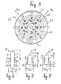
- the measuring part furthermore has a measuring plate 58 enclosed by the outer ring 56, in which three concentric recesses 51, 53, 57 with depth decreasing towards the center of the measuring plate 58 are driven from below. Therefore, an inner deformation ring 62 projects between the punctures 51 and 53 and an outer deformation ring 64 projects between the punctures 53 and 57, the two deformation rings having practically the same thickness and the free, planar end surfaces 61, 63 of the two deformation rings 62, 64 lie in one plane.
- This plane is the above-mentioned sensor plane 66, which extends horizontally after installation of the measuring body 50 according to FIG.
- the two annular end surfaces 61, 63 strain gauges are applied, as Figure 5 shows. Under the influence of the forces Q and Y the inner inclines Deformation ring 62 inwardly and outer deformation ring 64 slopes radially outward.
- a first group of eight strain gauges 1, 2, 3, 4, 5, 6, 7, 8 is applied on the end face 63 and on the end face 61, of which the first four are 1... 4 crosswise opposite one another on the outer end surface 63 and the remaining four in the same way are arranged crosswise opposite each other on the inner end face 61.
- the strain gauges 1 to 8 are connected in such a way to form a bridge 17, that between the strips 1 and 5 and 4 and 8, a supply voltage U o is applied.
- the output signal U Q from this bridge is tapped between strips 2 and 7 and between strips 6 and 3.
- a second group of strain gauges 9, 10, 11, 12, 13, 14, 15, 16 is also applied, each of which strip is arranged centrally in the circumferential direction between two adjacent strips of the first group. Further, each pair is 9, 10; 11, 12; 13, 14; 15, 16 of strips, one of which sits on the outer end face 63 and the other strip of the same radius on the inner end face 61, with respect to the common center of the deformation rings 62, 64 exactly opposite another pair of strips. Each four strips of two opposing pairs are connected together to form a bridge 18, 19 according to Figures 7 and 8. It can be seen that the strips 9, 10, 11, 12 lying on a common diameter, which faces, for example, in the direction of My, form the bridge circuit 18, while the strain gauges 13, 14, 15, 16 lying on the common diameter Mx form the bridge circuit 19 form.
- the output signal U Mx from the bridge 18 is taken off at the electrical connection points of the strips 9 and 10 or 12 and 11 lying in the circumferential direction. Accordingly, the output signal U My from bridge 19 at the electrical connection points of the circumferentially equal strips 13, 14 of a pair of strips or 15, 16 of the opposite pair of strips is removed.
- the three output signals U Q , U Mx and U My from the bridges 17, 18 and 19 are fed to an electronic evaluation device 70 (FIG. 9), not shown.
- the output signal U Q from the bridge 17 allows the detection of the normal load by the force Q.
- the output signal U Mx from the bridge 18 allows the detection of the moment caused by the force Y in a direction Mx and the output signal U My from the bridge 19 allowed the detection of the moment in a direction Mx perpendicular direction My in the defined by the end faces 61, 63 sensor plane 66.
- the output signals U Mx and U My from the bridges 18 and 19 with the predetermined distance d of the sensor plane 38 of the rail 20 combined in the evaluation device 70, for example, by the parameter d is input via the associated terminal in the evaluation.
- the embodiment of the invention according to Figures 4 and 5 can be changed such that the two deformation rings 62, 64 protrude at different heights from the measuring plate 58 down.
- the end face 63 of the deformation ring 64 then defines the first sensor plane 66 and the end face 61 of the inner deformation ring 62 defines a second sensor plane 68 which extends parallel to the sensor plane 66 at a distance given by the height difference of the deformation rings 62, 64.
- the strain gauges 1 to 16 can also be arranged and interconnected in this case as described above, wherein only in the evaluation device 70, the height difference must be taken into account by a correction factor.
Landscapes
- Physics & Mathematics (AREA)
- General Physics & Mathematics (AREA)
- Force Measurement Appropriate To Specific Purposes (AREA)
Applications Claiming Priority (1)
| Application Number | Priority Date | Filing Date | Title |
|---|---|---|---|
| DE102005057473A DE102005057473B4 (de) | 2005-11-30 | 2005-11-30 | Verfahren und Vorrichtung zur Erfassung von auf eine Schiene einwirkenden Kräften |
Publications (2)
| Publication Number | Publication Date |
|---|---|
| EP1793211A2 true EP1793211A2 (fr) | 2007-06-06 |
| EP1793211A3 EP1793211A3 (fr) | 2009-08-19 |
Family
ID=37708144
Family Applications (1)
| Application Number | Title | Priority Date | Filing Date |
|---|---|---|---|
| EP06022794A Withdrawn EP1793211A3 (fr) | 2005-11-30 | 2006-11-02 | Appareil et procédé de détermination des forces exercées sur un rail. |
Country Status (2)
| Country | Link |
|---|---|
| EP (1) | EP1793211A3 (fr) |
| DE (1) | DE102005057473B4 (fr) |
Cited By (7)
| Publication number | Priority date | Publication date | Assignee | Title |
|---|---|---|---|---|
| RU2376561C1 (ru) * | 2008-05-20 | 2009-12-20 | Виктор Алексеевич ЛУЧКИН | Рельсовая подкладка |
| RU2376559C1 (ru) * | 2008-05-20 | 2009-12-20 | Виктор Алексеевич ЛУЧКИН | Способ измерения веса и диагностики железнодорожного транспорта под подошвой рельса с применением весовой рельсовой подкладки |
| RU2376560C1 (ru) * | 2008-05-20 | 2009-12-20 | Виктор Алексеевич ЛУЧКИН | Весы для взвешивания подвижных железнодорожных объектов в движении и статике с применением рельсовой подкладки |
| WO2010142073A1 (fr) * | 2009-06-08 | 2010-12-16 | 中国铁道科学研究院机车车辆研究所 | Procédé et dispositif de mesure en continu de l'effort vertical roue-rail en se basant sur la déformation du rail |
| WO2013043701A1 (fr) | 2011-09-19 | 2013-03-28 | International Electronic Machines Corporation | Prise en compte d'évaluation d'objet pour forces dynamiques associées à un mouvement |
| CN104260752A (zh) * | 2014-09-30 | 2015-01-07 | 中国铁道科学研究院铁道建筑研究所 | 轮轨力的综合测试方法及装置 |
| JPWO2020202821A1 (fr) * | 2019-04-03 | 2020-10-08 |
Families Citing this family (2)
| Publication number | Priority date | Publication date | Assignee | Title |
|---|---|---|---|---|
| DE102008018076B4 (de) | 2008-04-09 | 2016-03-31 | Schenck Process Gmbh | System zur Messung von Belastungen beim Rad/Schiene-Kontakt von Schienenfahrzeugen |
| CN102072791B (zh) * | 2009-11-21 | 2012-04-04 | 杭州钱江称重技术有限公司 | 动静态四合一轨垫传感器 |
Citations (1)
| Publication number | Priority date | Publication date | Assignee | Title |
|---|---|---|---|---|
| EP1645859A1 (fr) * | 2003-06-17 | 2006-04-12 | Nitta Corporation | Capteur multi-axe |
Family Cites Families (14)
| Publication number | Priority date | Publication date | Assignee | Title |
|---|---|---|---|---|
| US4170268A (en) * | 1977-04-22 | 1979-10-09 | Flintab Ab | Apparatus for weighing railway supported vehicles |
| US4459863A (en) * | 1982-08-09 | 1984-07-17 | Safelink Ab | Shear beam load cell |
| GB8427304D0 (en) * | 1984-10-29 | 1984-12-05 | Davy Mckee Sheffield | Weighing device |
| DE3504276C1 (de) * | 1985-02-08 | 1986-07-24 | T. Nikolaus 7530 Pforzheim Württemberger | Wandler |
| US4869133A (en) * | 1988-06-24 | 1989-09-26 | Novatek Medical Inc. | Device for removing and retaining contaminated stoppers |
| DE3937318C1 (en) * | 1989-11-09 | 1991-05-23 | Carl Schenck Ag, 6100 Darmstadt, De | Force measuring unit with two concentric deformation rings - having electromechanical strain gauges on surface providing electrical values |
| US5111702A (en) * | 1990-06-22 | 1992-05-12 | Hottinger Baldwin Measurements, Inc. | Torsion ring transducer |
| DE4117924C1 (en) * | 1991-05-31 | 1992-12-17 | Messerschmitt-Boelkow-Blohm Gmbh, 8012 Ottobrunn, De | Vertical and side force components measuring appts. for railway vehicle wheel - achieves simultaneous evaluation using circuits coupled to expansion measuring strips applied to opposite sides of crown of rail |
| JP3745107B2 (ja) * | 1997-08-28 | 2006-02-15 | Jfeアドバンテック株式会社 | ロードセル及びロードセルを備える荷重検出装置 |
| GB2364124B (en) * | 2000-05-10 | 2004-03-31 | Serco Railtest Ltd | Load measuring |
| DE10031092A1 (de) * | 2000-06-30 | 2002-01-10 | Schenck Process Gmbh | Wägevorrichtung für Schienenfahrzeuge |
| DE10347812B4 (de) * | 2003-10-10 | 2014-07-10 | Hottinger Baldwin Messtechnik Gmbh | Kraftmessvorrichtung zur Erfassung der Schienenbelastung |
| JP4303091B2 (ja) * | 2003-11-10 | 2009-07-29 | ニッタ株式会社 | 歪みゲージ型センサおよびこれを利用した歪みゲージ型センサユニット |
| DE102005036608B3 (de) * | 2005-08-01 | 2006-12-14 | Schenck Process Gmbh | Verfahren und Vorrichtung zur Erfassung der Krafteinwirkung auf eine Schiene |
-
2005
- 2005-11-30 DE DE102005057473A patent/DE102005057473B4/de not_active Expired - Fee Related
-
2006
- 2006-11-02 EP EP06022794A patent/EP1793211A3/fr not_active Withdrawn
Patent Citations (1)
| Publication number | Priority date | Publication date | Assignee | Title |
|---|---|---|---|---|
| EP1645859A1 (fr) * | 2003-06-17 | 2006-04-12 | Nitta Corporation | Capteur multi-axe |
Cited By (10)
| Publication number | Priority date | Publication date | Assignee | Title |
|---|---|---|---|---|
| RU2376561C1 (ru) * | 2008-05-20 | 2009-12-20 | Виктор Алексеевич ЛУЧКИН | Рельсовая подкладка |
| RU2376559C1 (ru) * | 2008-05-20 | 2009-12-20 | Виктор Алексеевич ЛУЧКИН | Способ измерения веса и диагностики железнодорожного транспорта под подошвой рельса с применением весовой рельсовой подкладки |
| RU2376560C1 (ru) * | 2008-05-20 | 2009-12-20 | Виктор Алексеевич ЛУЧКИН | Весы для взвешивания подвижных железнодорожных объектов в движении и статике с применением рельсовой подкладки |
| WO2010142073A1 (fr) * | 2009-06-08 | 2010-12-16 | 中国铁道科学研究院机车车辆研究所 | Procédé et dispositif de mesure en continu de l'effort vertical roue-rail en se basant sur la déformation du rail |
| WO2013043701A1 (fr) | 2011-09-19 | 2013-03-28 | International Electronic Machines Corporation | Prise en compte d'évaluation d'objet pour forces dynamiques associées à un mouvement |
| EP2758758A4 (fr) * | 2011-09-19 | 2015-07-29 | Int Electronic Machines Corp | Prise en compte d'évaluation d'objet pour forces dynamiques associées à un mouvement |
| US9121747B2 (en) | 2011-09-19 | 2015-09-01 | International Electronic Machines Corp. | Object evaluation accounting for motion-related dynamic forces |
| CN104260752A (zh) * | 2014-09-30 | 2015-01-07 | 中国铁道科学研究院铁道建筑研究所 | 轮轨力的综合测试方法及装置 |
| CN104260752B (zh) * | 2014-09-30 | 2018-01-02 | 中国铁道科学研究院铁道建筑研究所 | 轮轨力的综合测试方法及装置 |
| JPWO2020202821A1 (fr) * | 2019-04-03 | 2020-10-08 |
Also Published As
| Publication number | Publication date |
|---|---|
| DE102005057473B4 (de) | 2012-09-20 |
| DE102005057473A1 (de) | 2007-06-06 |
| EP1793211A3 (fr) | 2009-08-19 |
Similar Documents
| Publication | Publication Date | Title |
|---|---|---|
| DE2356671A1 (de) | Waagetisch | |
| DE102005057473B4 (de) | Verfahren und Vorrichtung zur Erfassung von auf eine Schiene einwirkenden Kräften | |
| EP1904356B1 (fr) | Procede et dispositif permettant de determiner le risque de deraillement de vehicules ferroviaires | |
| EP2378263B1 (fr) | Système et procédé de détermination du centre de gravité de la masse dans des véhicules sur rails | |
| DE69308848T2 (de) | Wägevorrichtung für schienenfahrzeuge | |
| EP1847819B1 (fr) | Section de mesure sur un rail | |
| DE102007044186A1 (de) | Schiebetritt für Schienenfahrzeuge | |
| DE10347812B4 (de) | Kraftmessvorrichtung zur Erfassung der Schienenbelastung | |
| DE10241320A1 (de) | Vorrichtung zur Erfassung von Veränderungen an Eisenbahnrädern im Betriebseinsatz | |
| EP1147383B1 (fr) | Dispositif de pesage pour vehicules sur rails | |
| WO2002003040A1 (fr) | Dispositif de pesee pour vehicules sur rails | |
| AT516459B1 (de) | Vorrichtung zur Erfassung von Schienenverformungen | |
| DE102017003162A1 (de) | Verfahren und System zur Messung von auf eine Eisenbahnschiene wirkenden Kräften Y und Q und zur Bestimmung des Verhältnisses dieser Kräfte Y/Q | |
| EP1409790B1 (fr) | Traverse servant de support aux rails de chemins de fer | |
| DE10315666B4 (de) | Verfahren zur Kalibrierung einer Radkraft-Messanlage | |
| DE3873901T2 (de) | Vorrichtung zur messung des gewichts. | |
| DE102005036608B3 (de) | Verfahren und Vorrichtung zur Erfassung der Krafteinwirkung auf eine Schiene | |
| EP1584536B1 (fr) | Dispositif de mesure de force pour la détection de la charge sur les rails | |
| DE102016001342B3 (de) | Kraftmessvorrichtung zur Ermittlung der Radaufstandskräfte schienengebundener Fahrzeuge | |
| EP1141667B1 (fr) | Dispositif de pesage pour vehicules sur rails | |
| DE2043484C3 (de) | Vorrichtung zum Messen der Belastungen, die durch Fahren von Fahrzeugen auf einer Straße aufgebracht werden | |
| DE10356867A1 (de) | Messeinrichtung für die Radsatzdiagnose und zum Erfassen von Radaufstandskräften von Schienenfahrzeugen | |
| DE102006059896B3 (de) | Kraftmessvorrichtung | |
| EP0338553A2 (fr) | Balance pour véhicules de chemin de fer | |
| DE102007001626B4 (de) | Mobile Messeinrichtung zum Erfassen von Radlasten von Schienenfahrzeugen |
Legal Events
| Date | Code | Title | Description |
|---|---|---|---|
| PUAI | Public reference made under article 153(3) epc to a published international application that has entered the european phase |
Free format text: ORIGINAL CODE: 0009012 |
|
| AK | Designated contracting states |
Kind code of ref document: A2 Designated state(s): AT BE BG CH CY CZ DE DK EE ES FI FR GB GR HU IE IS IT LI LT LU LV MC NL PL PT RO SE SI SK TR |
|
| AX | Request for extension of the european patent |
Extension state: AL BA HR MK YU |
|
| PUAL | Search report despatched |
Free format text: ORIGINAL CODE: 0009013 |
|
| AK | Designated contracting states |
Kind code of ref document: A3 Designated state(s): AT BE BG CH CY CZ DE DK EE ES FI FR GB GR HU IE IS IT LI LT LU LV MC NL PL PT RO SE SI SK TR |
|
| AX | Request for extension of the european patent |
Extension state: AL BA HR MK RS |
|
| RIC1 | Information provided on ipc code assigned before grant |
Ipc: G01G 3/14 20060101ALI20090713BHEP Ipc: G01L 5/16 20060101ALI20090713BHEP Ipc: G01L 1/22 20060101ALI20090713BHEP Ipc: G01G 19/04 20060101AFI20070212BHEP |
|
| 17P | Request for examination filed |
Effective date: 20100217 |
|
| AKX | Designation fees paid |
Designated state(s): AT BE BG CH CY CZ DE DK EE ES FI FR GB GR HU IE IS IT LI LT LU LV MC NL PL PT RO SE SI SK TR |
|
| 17Q | First examination report despatched |
Effective date: 20100409 |
|
| STAA | Information on the status of an ep patent application or granted ep patent |
Free format text: STATUS: THE APPLICATION IS DEEMED TO BE WITHDRAWN |
|
| 18D | Application deemed to be withdrawn |
Effective date: 20160601 |