EP1793302A2 - Informationsverarbeitungsvorrichtung - Google Patents
Informationsverarbeitungsvorrichtung Download PDFInfo
- Publication number
- EP1793302A2 EP1793302A2 EP06077002A EP06077002A EP1793302A2 EP 1793302 A2 EP1793302 A2 EP 1793302A2 EP 06077002 A EP06077002 A EP 06077002A EP 06077002 A EP06077002 A EP 06077002A EP 1793302 A2 EP1793302 A2 EP 1793302A2
- Authority
- EP
- European Patent Office
- Prior art keywords
- door
- main body
- elastic member
- mounting slot
- hinge
- Prior art date
- Legal status (The legal status is an assumption and is not a legal conclusion. Google has not performed a legal analysis and makes no representation as to the accuracy of the status listed.)
- Pending
Links
Images


Classifications
-
- G—PHYSICS
- G06—COMPUTING OR CALCULATING; COUNTING
- G06F—ELECTRIC DIGITAL DATA PROCESSING
- G06F1/00—Details not covered by groups G06F3/00 - G06F13/00 and G06F21/00
- G06F1/16—Constructional details or arrangements
- G06F1/1613—Constructional details or arrangements for portable computers
- G06F1/1633—Constructional details or arrangements of portable computers not specific to the type of enclosures covered by groups G06F1/1615 - G06F1/1626
- G06F1/1656—Details related to functional adaptations of the enclosure, e.g. to provide protection against EMI, shock, water, or to host detachable peripherals like a mouse or removable expansions units like PCMCIA cards, or to provide access to internal components for maintenance or to removable storage supports like CDs or DVDs, or to mechanically mount accessories
-
- G—PHYSICS
- G06—COMPUTING OR CALCULATING; COUNTING
- G06F—ELECTRIC DIGITAL DATA PROCESSING
- G06F1/00—Details not covered by groups G06F3/00 - G06F13/00 and G06F21/00
- G06F1/16—Constructional details or arrangements
- G06F1/1601—Constructional details related to the housing of computer displays, e.g. of CRT monitors, of flat displays
- G06F1/1607—Arrangements to support accessories mechanically attached to the display housing
-
- G—PHYSICS
- G06—COMPUTING OR CALCULATING; COUNTING
- G06F—ELECTRIC DIGITAL DATA PROCESSING
- G06F1/00—Details not covered by groups G06F3/00 - G06F13/00 and G06F21/00
- G06F1/16—Constructional details or arrangements
- G06F1/1613—Constructional details or arrangements for portable computers
- G06F1/1626—Constructional details or arrangements for portable computers with a single-body enclosure integrating a flat display, e.g. Personal Digital Assistants [PDAs]
Definitions
- the present general inventive concept relates to an information processing apparatus, and more particularly, to an information processing apparatus having an improved door configuration to open and close a mounting slot to which a peripheral device such as a secure digital (SD) card is detachably attached.
- a peripheral device such as a secure digital (SD) card
- an information processing apparatus processes various information to provide convenience to a user.
- the information processing apparatus may comprise an MP3 player, a personal digital assistant (PDA), a cell phone, a digital camera, a digital photo frame, and a portable multimedia player (PMP).
- the information processing apparatus may further comprise a portable computer.
- the information processing apparatus is small-sized to be portable.
- the information processing apparatus comprises a front cover and a rear cover which are coupled with each other.
- a circuit such as a printed circuit board (PCB)
- PCB printed circuit board
- the rear cover is coupled with the front cover and protects the circuit.
- the information processing apparatus comprises a mounting slot to which a peripheral device, such as a secure digital (SD) card, a compact flash (CF) card, a multi media card (MMC), and a universal serial bus (USB), is detachably attached.
- SD secure digital
- CF compact flash
- MMC multi media card
- USB universal serial bus
- United States Patent No. 6,421,247 filed on July 16, 2002 , describes a door slot locking mechanism of a digital camera as a kind of information processing apparatus.
- the conventional door slot locking mechanism comprises a camera body, a card slot which is formed on the camera body, and a card slot door which opens and closes the card slot to prevent dirt from being introduced to the card slot.
- the conventional door slot locking mechanism further comprises a rod and a torsion coil spring which couple opposite ends of the card slot door with the camera body, and a pair of door elastic members which are provided on a center of the card slot door and comprise a torsion coil spring.
- a projection is formed on the camera body to limit the door elastic member from rotating.
- the door elastic member is limited from rotating by the projection of the camera body.
- the memory card presses the door elastic member to separate it from the projection of the camera body.
- the card slot door rotates and the memory card is inserted into the card slot.
- the card slot door rotates in a closing position by the torsion coil spring coupled with the rod.
- the card slot door configuration to open and close the card slot is complex.
- the conventional information processing apparatus is not easily assembled, leading to a rise of production costs.
- the present general inventive concept provides an information processing apparatus which has an improved door configuration for a mounting slot, to be easily assembled and to stably open and close the door.
- an information processing apparatus comprising a main body casing which has a mounting slot to insertably mount a peripheral device, a door which is rotatably coupled with the main body casing to open and close the mounting slot, and an elastic member which is coupled with the main body casing to elastically press the door when the door rotates.
- the main body casing may comprise a plurality of door slots which are formed adjacent to the mounting slot to rotatably guide the door between a closing position and an opening position, and an elastic member supporter which is formed on a plate surface of the main body casing and couples with the elastic member to support the elastic member to remain coupled to the main body.
- the elastic member may comprise a mounting part which is formed on a first side thereof and couples with the elastic member supporter, and a keeping part which has at least one elastic projection provided on a second side thereof and is inserted into the door slots to press the door when rotating.
- the elastic member supporter may comprise a position determining pin which is formed on a plate surface thereof, and the mounting part comprises a position determining pin hole which couples with the position determining pin.
- the apparatus may further comprise a hinge part having a hinge shaft which is provided on one of the door and the main body casing, and a hinge shaft accommodating groove which is formed on the other one of the door and the main body casing and coupled with the hinge shaft.
- the elastic member may press on a portion of the hinge shaft as the door rotates.
- the main body casing may comprise a door grip to press and open the door in the closing position.
- the elastic member supporter may comprise sliding grooves which face each other, and may slidably guide an end part of the mounting part.
- the elastic projection may be formed on the keeping part to press the door in the opening position of the door.
- an information processing apparatus comprising a main body having a mounting slot to insertably mount a peripheral device to the information processing apparatus, a door rotatably coupled to the main body to rotate between an open position to expose the mounting slot and a closed position to cover the mounting slot, and an elastic member coupled to the main body and the door to press against a portion of the door as the door rotates and to bias the door to maintain at least one of the closed position and the open position.
- the elastic member may bias the door to maintain the closed position.
- the elastic member may bias the door to maintain the open position.
- the elastic member may comprise a mounting part to couple the elastic member to the main body, and a keeping part having one or more elastic projections to press against the door as it rotates and to bias the door to maintain one of the closed position and the open position.
- the apparatus may further comprise at least one hinge shaft coupled to one of the door and the main body to guide the rotation of the door, and at least one hinge shaft accommodation part couple to another one of the door and the main body to couple to the hinge shaft.
- the elastic member may press against the hinge shaft as the portion of the door the elastic member presses.
- an information processing apparatus comprising a main body having a mounting slot to insertably mount a peripheral device to the information processing apparatus, a door having curved hinge shafts to couple with the main body to cover and uncover the mounting slot, hinge accommodation parts disposed on the main body at sides of the mounting slot to couple with the curved hinge shafts and to guide a rotating movement of the door.
- the apparatus may further comprise an elastic member coupled to the main body and the door to press against the curved hinge shafts as the door rotates and to bias the door to maintain a predetermined position.
- the elastic member may comprise a mounting part to couple the elastic member to the main body, and a keeping part having one or more elastic projections to press against the curved hinge shafts as the door rotates and to bias the door to maintain the predetermined position.
- an information processing apparatus comprising a main body including a mounting slot to insertably mount a peripheral device and a hinge mounting portion disposed at each side of the mounting slot to engage with respective door hinges, and a door including door hinges to engage with the respective hinge mounting portions to rotatably open and close access to the mounting slot.
- the apparatus may further comprise an elastic member coupled to the main body and the door to press against the door hinge as the door rotates.
- the door hinges may be curved such that a pressure applied by the elastic member to the curved door hinge biases the door to maintain at least one of a closed position and an open position.
- an information processing apparatus 10 may comprise a main body casing 30 which has a mounting slot 35 to which a peripheral device 20 (see FIG. 4B) can be detachably attached, a door 50 which is coupled with the main body casing 30 by a hinge to rotatably open and close the mounting slot 35, and an elastic member 70 which is coupled with the main body casing 30 to elastically press the door 50 when the door 50 rotatably opens and closes the mounting slot 35.
- the information processing apparatus 10 may further comprise hinge parts 60 which have hinge shafts 61 which are formed on the main body casing 30, and hinge shaft accommodating grooves 63 which are provided on the door 50 to be coupled with the hinge shafts 61.
- the information processing apparatus 10 may comprise an MP3 player, a personal digital assistant (PDA), a cell phone, a digital photo frame, and a portable multimedia player (PMP), by way of example.
- the information processing apparatus may further comprise a display apparatus such as a monitor of a personal computer which displays a signal input from an external signal source, as well as a portable computer.
- a display apparatus such as a monitor of a personal computer which displays a signal input from an external signal source, as well as a portable computer.
- the digital photo frame will be described as an example of the information processing apparatus 10 according to the present general inventive concept.
- the information processing apparatus 10 such as the digital photo frame, may comprise a display panel 15 which displays an image thereon; a front cover 31 which comprises an opening to accommodate the display panel 15; and a rear cover 33 which is coupled with the front cover 31.
- a circuit like a printed circuit board (PCB) can be provided in the front cover 31.
- the rear cover 33 is coupled with the front cover 31 to protect the circuit.
- the information processing apparatus 10 further comprises a supporting bracket 34 which is installed on an installing surface such as a table to support the main body casing 30.
- the peripheral device 20 is mounted in the mounting slot 35 (to be described later) to transmit/receive information or data.
- the peripheral device 20 may comprise a secure digital (SD) card, a compact flash (CF) card, a multi media card (MMC), a universal serial bus (USB) memory, and the like.
- SD secure digital
- CF compact flash
- MMC multi media card
- USB universal serial bus
- the main body casing 30 forms an external appearance of the information processing apparatus 10 as the front cover 31 and the rear cover 33 are coupled with each other.
- the main body casing 30 comprises the mounting slot 35 to which the peripheral device 20 is detachably attached; and the door 50 which rotatably opens and closes the mounting slot 35.
- the peripheral device 20 to transmit/receive information or data is insertably mounted to the mounting slot 35.
- the door 50 is adjacent to the mounting slot 35 to prevent dirt from being introduced to the mounting slot 35.
- door slots 37a and 37b are formed on opposite end parts of the mounting slot 35 of the main body casing 30 to guide the door 50 to rotate between an opening position and a closing position.
- the length of the door slots 37a and 37b may change according to a rotation direction of the door 50 to adjust a rotation angle of the door 50.
- An elastic member supporter 39 is formed on a plate surface of the main body casing 30 and coupled with a mounting part 71 (to be described later).
- the elastic member supporter 39 comprises a position determining pin 41 which is formed on a plate surface thereof.
- a through hole (not illustrated) is provided on the elastic member supporter 39 to be coupled with a coupling unit such as a screw so that the elastic member 70 is coupled with the front cover 31 and the rear cover 33.
- the position determining pin 41 is formed on the plate surface of the elastic member supporter 39 and accommodated in a position determining pin hole 77 of the elastic member 70 to support the elastic member 70.
- the elastic member 70 may be stably supported during assembling, etc.
- a door grip 45 can be formed on the plate surface of the main body casing 30 so that a user can open the door 50 from a closed position. Thus, a user may open the door 50 without difficulty.
- the door 50 is coupled with the main body casing 30 by a hinge to rotatably open and close the mounting slot 35.
- the door 50 may comprise a door main body 51 which has a shape corresponding to that of the mounting slot 35, and a pair of door arms 53 which are formed on a plate surface of the door main body 51 facing toward the inside of the main body casing 30 and extend from end parts of the door main body 51.
- the hinge shaft accommodating grooves 63 are formed on the end parts of the door arms 53 to be engaged with the hinge shafts 61.
- each of the hinge parts 60 comprises the hinge shaft 61 which is formed on the plate surface of the main body casing 30, and the hinge shaft accommodating groove 63 which is formed on the door arm 53 to be engaged with the hinge shaft 61.
- the hinge shafts 61 are formed on the plate surface of the main body casing 30 to extend toward the door arms 53, the present general inventive concept is not limited thereto, and the hinge shafts 61 may alternatively be formed on the door arms 53.
- the hinge shaft accommodating grooves 63 are illustrated in FIG. 2 as formed on the opposite end parts of the door arms 53, the present general inventive concept is not limited thereto, and the hinge shaft accommodating grooves 63 may alternatively be formed on the main body casing 30.
- the hinge shafts 61 and the hinge shaft accommodating grooves 63 are coupled with each other to generate a predetermined friction force, and maintain an opening angle of the door 50 in a predetermined position.
- the door 50 can rotate stably by the hinge parts 60 between the opening position and the closing position.
- the elastic member 70 is coupled with the main body casing 30 to elastically press the door 50 while the door is rotating.
- the elastic member 70 comprises the mounting part 71 which is provided on a first side thereof and is coupled with the elastic member supporter 39, and a keeping part 73 comprising at least one elastic projection 75 which is provided on a second side of the elastic member 70 and inserted into the door slots 37a and/or 37b to elastically press the door 50.
- the elastic member 70 may be formed of a single plate with a simple configuration. While in the present embodiment there is provided one elastic member 70, the present general inventive concept is not limited thereto, and there may be provided two elastic members 70 to respectively press the pair of door arms 53 according to the size of the peripheral device 20 or of the information processing apparatus 10.
- the mounting part 71 can be bent from the plate to be coupled with the elastic member supporter 39 and to support the elastic member 70.
- the elastic member 70 may be supported by the main body casing 30 more stably.
- the keeping part 73 can be bent from the plate and comprises at least one elastic projection 75 which is formed on the plate surface to be inserted into the door slots 37a and/or 37b and to elastically press the door 50.
- the elastic projection 75 is formed on the plate surface of the keeping part 73 inserted into the door slots 37a and/or 37b to press the door arms 53 while the door 50 is rotating, to have a predetermined elastic force.
- the size of the elastic projection 75 may be changed corresponding to the size of the door arms 53 to press the door arms 53 when the door is in the opening position.
- the door 50 may stably open and close the mounting slot 35 with a simple configuration.
- a projection accommodating groove (not illustrated) may be formed on the door arms 53 to be coupled with the elastic projection 75 so that the door 50 remains locked in the closing position, according to the size of the mounting slot 35 or of the door 50.
- the position determining pin hole 77 can be formed on the mounting part 71 of the elastic member 70 to be coupled with the position determining pin 41.
- a coupling hole 79 can be formed on the mounting part 71 to couple the front cover 31 and the rear cover 33 through a coupler, such as a screw.
- the elastic member 70 may be supported to the main body casing 30 as the front cover 31 is coupled with the rear cover 33.
- the keeping part 73 of the elastic member 70 contacts an internal wall of the door slots 37a and/or 37b.
- the elastic member 70 is coupled with the main body casing 30.
- the door arms 53 are inserted into the door slots 37a and 37b to press the door main body 51, thereby coupling the hinge shafts 61 with the hinge shaft accommodating grooves 63.
- the mounting part 71 of the elastic member 70 is disposed between the front cover 31 and the rear cover 33 to couple them with each other.
- the main body casing 30 is coupled with the supporting bracket 34, thereby completing the assembling process.
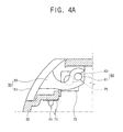
- FIGS. 4A and 4B which illustrate the door 50 in the closing and the opening position, respectively, the opening and closing process of the door 50 will be described.
- the elastic projection 75 of the keeping part 73 elastically presses the door arms 53 so that the door 50 closes the mounting slot 35.
- the door grip 45 When a user contacts the door grip 45 and presses the door main body 51 to open the door 50 and to insert the peripheral device 20, such as an SD card, into the mounting slot 35, the door 50 rotates by the hinge 60 and opens.
- the elastic projection 75 continuously presses the door arms 53, the door 50 is opened stably and securely. Also, the door 50 rotates smoothly and easily.
- an information processing apparatus 10 may comprise a main body casing 30 (not illustrated) which has a mounting slot 35 to which a peripheral device 20 (not illustrated) is detachably attached, a door 50 (not illustrated) which is coupled with the main body casing 30 by a hinge to rotatably open and close the mounting slot 35, and an elastic member 70 which is coupled with the main body casing 30 to press the door 50 in a closing position and to make the door remain locked.
- An elastic member supporter 39 comprises sling grooves 43 which face each other to slidably guide an end part of the mounting part 71.
- the end part of the mounting part 71 is slidably guided by the sliding grooves 43 and supports the elastic member 70.
- the mounting part 71 according to the present embodiment of the present general inventive concept illustrated in FIG. 5 does not comprise a position determining pin hole 77, and the sliding grooves 43 are formed on the elastic supporter 39. Thus, in the present embodiment the elastic member 70 is inserted into the sliding grooves 43.
- the mounting part 71 does not comprise a position determining pin hole 77, and the sliding grooves 43 are formed on the elastic supporter 39.
- the elastic member 70 is inserted into the sliding grooves 43.
- the present general inventive concept is not limited thereto, and the general inventive concept can also be applicable to a portable information processing apparatus, such as a PDA and a PMP.
- the exemplary embodiment of the present general inventive concept may be applicable to a door configuration to mount a battery as well as a peripheral device such as an SD card.
- the door configuration which rotatably opens and closes the mounting slot becomes simplified. Also, the information processing apparatus is assembled without difficulty, thereby reducing assembling time and costs.
Landscapes
- Engineering & Computer Science (AREA)
- Theoretical Computer Science (AREA)
- Computer Hardware Design (AREA)
- General Engineering & Computer Science (AREA)
- Human Computer Interaction (AREA)
- Physics & Mathematics (AREA)
- General Physics & Mathematics (AREA)
- Casings For Electric Apparatus (AREA)
Applications Claiming Priority (1)
| Application Number | Priority Date | Filing Date | Title |
|---|---|---|---|
| KR1020050116558A KR101236391B1 (ko) | 2005-12-01 | 2005-12-01 | 정보처리장치 |
Publications (1)
| Publication Number | Publication Date |
|---|---|
| EP1793302A2 true EP1793302A2 (de) | 2007-06-06 |
Family
ID=37769827
Family Applications (1)
| Application Number | Title | Priority Date | Filing Date |
|---|---|---|---|
| EP06077002A Pending EP1793302A2 (de) | 2005-12-01 | 2006-11-10 | Informationsverarbeitungsvorrichtung |
Country Status (4)
| Country | Link |
|---|---|
| US (1) | US7448898B2 (de) |
| EP (1) | EP1793302A2 (de) |
| KR (1) | KR101236391B1 (de) |
| CN (1) | CN1976568A (de) |
Cited By (1)
| Publication number | Priority date | Publication date | Assignee | Title |
|---|---|---|---|---|
| CN103260369A (zh) * | 2012-02-17 | 2013-08-21 | 纬创资通股份有限公司 | 盖板机构及其相关电子装置 |
Families Citing this family (9)
| Publication number | Priority date | Publication date | Assignee | Title |
|---|---|---|---|---|
| CN201084083Y (zh) * | 2007-06-20 | 2008-07-09 | 鸿富锦精密工业(深圳)有限公司 | 接口盖板组合 |
| CN101472421B (zh) * | 2007-12-29 | 2010-11-17 | 精英电脑股份有限公司 | 面板的可滑动卡固结构 |
| JP4651699B2 (ja) * | 2008-07-14 | 2011-03-16 | レノボ・シンガポール・プライベート・リミテッド | 電子機器 |
| TWI365578B (en) * | 2008-10-15 | 2012-06-01 | Inventec Corp | Hinge structure with a dc-in |
| CN102065658B (zh) * | 2009-11-16 | 2013-04-03 | 和硕联合科技股份有限公司 | 电子装置 |
| CN102088827B (zh) * | 2009-12-02 | 2013-01-02 | 英华达股份有限公司 | 按键组配结构 |
| TWI462025B (zh) * | 2011-11-30 | 2014-11-21 | Wistron Corp | 具有可動式插卡結構之卡讀取器及電子裝置 |
| KR101923472B1 (ko) * | 2011-12-06 | 2018-11-29 | 엘지전자 주식회사 | 소켓 모듈 및 이를 구비한 단말기 |
| JP2014102541A (ja) * | 2012-11-16 | 2014-06-05 | Toshiba Corp | 情報機器 |
Family Cites Families (20)
| Publication number | Priority date | Publication date | Assignee | Title |
|---|---|---|---|---|
| US2750219A (en) * | 1952-07-11 | 1956-06-12 | Admiral Corp | Latch mechanism |
| DE7914232U1 (de) * | 1979-05-17 | 1979-08-23 | Paul Hettich & Co, 4983 Kirchlengern | Mit einer glastuer versehener schrank |
| JPS59146955U (ja) * | 1983-03-22 | 1984-10-01 | 山一電機工業株式会社 | 被接続器体取り出し装置付接続器 |
| US5222792A (en) * | 1988-05-10 | 1993-06-29 | Sharp Kabushiki Kaisha | Opening/closing device of a door member |
| JP2965420B2 (ja) * | 1992-06-11 | 1999-10-18 | 松下電器産業株式会社 | テープカセット蓋体装置 |
| US5701216A (en) * | 1995-02-21 | 1997-12-23 | Asahi Kogaku Kogyo Kabushiki Kaisha | Shutter mechanism for disk drive cartridge insertion opening |
| JP3590449B2 (ja) * | 1995-05-22 | 2004-11-17 | ペンタックス株式会社 | 電子現像型カメラ |
| KR0153836B1 (ko) * | 1995-11-20 | 1998-12-15 | 김광호 | 광학용 드라이브의 도어장치 |
| KR100247513B1 (ko) * | 1997-04-16 | 2000-04-01 | 윤종용 | 컴퓨터의 섀시 어셈블리 |
| KR100252198B1 (ko) | 1997-10-06 | 2000-04-15 | 박호군 | 식물 병원성 곰팡이에 대한 길항작용을 가진 바실러스속 균주 |
| KR100304190B1 (ko) | 1998-03-31 | 2001-10-19 | 윤종용 | 전자 디바이스를 위한 힌지가능하고 착탈가능한 액세스 도어 |
| KR200232049Y1 (ko) | 1998-12-02 | 2001-08-07 | 윤종용 | 액세스 도어를 갖는 휴대형 컴퓨터 |
| JP3638232B2 (ja) | 1999-08-27 | 2005-04-13 | ペンタックス株式会社 | カード挿脱機構 |
| US6332781B1 (en) * | 2000-04-06 | 2001-12-25 | Yazaki Corporation | Connector structure having dust/water droplet damage prevention capability |
| KR100793728B1 (ko) | 2001-09-14 | 2008-01-10 | 삼성전자주식회사 | 액정 표시 장치 |
| KR100512718B1 (ko) | 2002-07-16 | 2005-09-07 | 삼성전자주식회사 | 모니터장치 |
| KR100889534B1 (ko) | 2002-07-24 | 2009-03-23 | 엘지디스플레이 주식회사 | Lcd 모듈의 액정패널 고정구조 |
| KR200305308Y1 (ko) | 2002-10-14 | 2003-03-03 | 임형태 | 액정 모니터용 스탠드 |
| KR20040096097A (ko) | 2003-05-07 | 2004-11-16 | 여단열 | 스탠드형 액정표시장치 |
| JP2005079779A (ja) * | 2003-08-29 | 2005-03-24 | Seiko Epson Corp | カード読み書き装置、プリンタ及び画像入出力装置 |
-
2005
- 2005-12-01 KR KR1020050116558A patent/KR101236391B1/ko not_active Expired - Fee Related
-
2006
- 2006-11-10 EP EP06077002A patent/EP1793302A2/de active Pending
- 2006-11-24 CN CNA2006101628210A patent/CN1976568A/zh active Pending
- 2006-11-30 US US11/565,063 patent/US7448898B2/en not_active Expired - Fee Related
Cited By (1)
| Publication number | Priority date | Publication date | Assignee | Title |
|---|---|---|---|---|
| CN103260369A (zh) * | 2012-02-17 | 2013-08-21 | 纬创资通股份有限公司 | 盖板机构及其相关电子装置 |
Also Published As
| Publication number | Publication date |
|---|---|
| US7448898B2 (en) | 2008-11-11 |
| KR101236391B1 (ko) | 2013-02-22 |
| US20070128918A1 (en) | 2007-06-07 |
| CN1976568A (zh) | 2007-06-06 |
| KR20070058210A (ko) | 2007-06-08 |
Similar Documents
| Publication | Publication Date | Title |
|---|---|---|
| EP3909228B1 (de) | Scharniermodul und klappbare elektronische vorrichtung damit | |
| EP3699728B1 (de) | Scharniermodul und klappbare elektronische vorrichtung damit | |
| KR100722240B1 (ko) | 힌지장치 및 그 힌지장치를 이용한 전자기기 | |
| US5090913A (en) | Portable apparatus having cable electrically connecting display unit and base unit | |
| US8513522B2 (en) | Shielding mechanism and electronic device | |
| US7447007B2 (en) | Portable computer | |
| US20090009955A1 (en) | Electronic apparatus having a connector connecting a disk drive | |
| US7448898B2 (en) | Information processing apparatus having a mounting slot and mounting slot door thereof | |
| US7428145B2 (en) | Electronic apparatus | |
| CN108322230B (zh) | 插卡装置及电子设备 | |
| EP1793303B1 (de) | Informationsverarbeitungsvorrichtung | |
| US5238421A (en) | Portable apparatus having cable electrically connecting display unit and base unit | |
| KR20020057436A (ko) | 휴대용컴퓨터 | |
| US7457109B2 (en) | Electronic apparatus | |
| US20110102982A1 (en) | Electronic apparatus | |
| TWI387338B (zh) | 顯示裝置之支撐結構 | |
| CN100426839C (zh) | 电子装置 | |
| US20070047197A1 (en) | Electronic apparatus | |
| US11962878B2 (en) | Electronic device | |
| US20110127184A1 (en) | Electronic apparatus with hinge mechanism | |
| US7147484B1 (en) | Electronic apparatus and board assembly | |
| US8582293B2 (en) | Portable electronic apparatus | |
| KR100548774B1 (ko) | 오피스장치를 포함하는 선바이저 | |
| US7283356B2 (en) | Electronic apparatus | |
| JP5466930B2 (ja) | 携帯型電子機器 |
Legal Events
| Date | Code | Title | Description |
|---|---|---|---|
| PUAI | Public reference made under article 153(3) epc to a published international application that has entered the european phase |
Free format text: ORIGINAL CODE: 0009012 |
|
| AK | Designated contracting states |
Kind code of ref document: A2 Designated state(s): AT BE BG CH CY CZ DE DK EE ES FI FR GB GR HU IE IS IT LI LT LU LV MC NL PL PT RO SE SI SK TR |
|
| AX | Request for extension of the european patent |
Extension state: AL BA HR MK YU |
|
| STAA | Information on the status of an ep patent application or granted ep patent |
Free format text: STATUS: THE APPLICATION IS DEEMED TO BE WITHDRAWN |
|
| D18D | Application deemed to be withdrawn (deleted) | ||
| 18D | Application deemed to be withdrawn |
Effective date: 20100601 |