EP1795110A2 - Composant pour appareil électroménager, en particulier pour un lave-vaisselle, et collecteur pour appareil électroménager, en particulier pour un lave-vaisselle, utilisant celui-ci - Google Patents
Composant pour appareil électroménager, en particulier pour un lave-vaisselle, et collecteur pour appareil électroménager, en particulier pour un lave-vaisselle, utilisant celui-ci Download PDFInfo
- Publication number
- EP1795110A2 EP1795110A2 EP06125307A EP06125307A EP1795110A2 EP 1795110 A2 EP1795110 A2 EP 1795110A2 EP 06125307 A EP06125307 A EP 06125307A EP 06125307 A EP06125307 A EP 06125307A EP 1795110 A2 EP1795110 A2 EP 1795110A2
- Authority
- EP
- European Patent Office
- Prior art keywords
- component
- sump
- container
- optical element
- light
- Prior art date
- Legal status (The legal status is an assumption and is not a legal conclusion. Google has not performed a legal analysis and makes no representation as to the accuracy of the status listed.)
- Withdrawn
Links
Images


Classifications
-
- A—HUMAN NECESSITIES
- A47—FURNITURE; DOMESTIC ARTICLES OR APPLIANCES; COFFEE MILLS; SPICE MILLS; SUCTION CLEANERS IN GENERAL
- A47L—DOMESTIC WASHING OR CLEANING; SUCTION CLEANERS IN GENERAL
- A47L15/00—Washing or rinsing machines for crockery or tableware
- A47L15/42—Details
- A47L15/4244—Water-level measuring or regulating arrangements
-
- D—TEXTILES; PAPER
- D06—TREATMENT OF TEXTILES OR THE LIKE; LAUNDERING; FLEXIBLE MATERIALS NOT OTHERWISE PROVIDED FOR
- D06F—LAUNDERING, DRYING, IRONING, PRESSING OR FOLDING TEXTILE ARTICLES
- D06F39/00—Details of washing machines not specific to a single type of machines covered by groups D06F9/00 - D06F27/00
- D06F39/08—Liquid supply or discharge arrangements
- D06F39/087—Water level measuring or regulating devices
-
- G—PHYSICS
- G01—MEASURING; TESTING
- G01F—MEASURING VOLUME, VOLUME FLOW, MASS FLOW OR LIQUID LEVEL; METERING BY VOLUME
- G01F23/00—Indicating or measuring liquid level or level of fluent solid material, e.g. indicating in terms of volume or indicating by means of an alarm
- G01F23/22—Indicating or measuring liquid level or level of fluent solid material, e.g. indicating in terms of volume or indicating by means of an alarm by measuring physical variables, other than linear dimensions, pressure or weight, dependent on the level to be measured, e.g. by difference of heat transfer of steam or water
- G01F23/28—Indicating or measuring liquid level or level of fluent solid material, e.g. indicating in terms of volume or indicating by means of an alarm by measuring physical variables, other than linear dimensions, pressure or weight, dependent on the level to be measured, e.g. by difference of heat transfer of steam or water by measuring the variations of parameters of electromagnetic or acoustic waves applied directly to the liquid or fluent solid material
- G01F23/284—Electromagnetic waves
- G01F23/292—Light, e.g. infrared or ultraviolet
- G01F23/2921—Light, e.g. infrared or ultraviolet for discrete levels
- G01F23/2922—Light, e.g. infrared or ultraviolet for discrete levels with light-conducting sensing elements, e.g. prisms
- G01F23/2925—Light, e.g. infrared or ultraviolet for discrete levels with light-conducting sensing elements, e.g. prisms using electrical detecting means
- G01F23/2927—Light, e.g. infrared or ultraviolet for discrete levels with light-conducting sensing elements, e.g. prisms using electrical detecting means for several discrete levels, e.g. with more than one light-conducting sensing element
Definitions
- the present invention relates to a component for a household appliance, in particular for a dishwasher, and to a sump for a household appliance, in particular for a dishwasher, using it.
- the present invention is particularly suited to the field of components and systems for household appliances, typically household-use machines for washing, in particular dishwashers.
- Such a device comprises a light source, adapted to generate a light beam, and a light detector, adapted to receive said light beam.
- An optical element fitted on the container wall is adapted to reflect the light beam only when there is liquid in the container.
- the light detector receives the light beam only when there is liquid in the container.
- Some types of household appliances comprise a tub adapted to contain liquid, at least during certain operating phases of the household appliance.
- Some of these types of household appliances, in particular dishwashers typically comprise a body defining a container fixed under the tub, adapted to collect the water drained from the latter, in particular to discharge it or recycle it for washing purposes, for example, through suitable pumps fitted on or built in said body; said body is generally called "sump".
- the main object of the present invention is to provide a device which can detect a liquid level in a container through optical means.
- Fig. 1 shows a diagram of a sensor element 1 comprising a light transmitter Tx, in particular a photodiode, adapted to generate a light beam F, and a light receiver Rx, in particular a phototransistor, adapted to receive said light beam F.
- a light transmitter Tx in particular a photodiode
- a light receiver Rx in particular a phototransistor
- Fig. 2 shows a circuit configuration comprising the sensor element 1; as illustrated, the light transmitter Tx and the light receiver Rx are connected to a positive power supply line +, in particular through respective resistors R1 and R2, and to a negative power supply line -.
- the light receiver Rx in particular the phototransistor collector, is connected to a terminal Vout; the potential difference between the terminal Vout and the negative power supply line - is indicative of the light received by the light receiver Rx; therefore, the terminal Vout can be used for detecting an electric signal corresponding to the light beam F emitted by the light transmitter Tx.
- Figs. 3 and 4 show the sensor element 1 in a first operating condition and in a second operating condition, respectively, in both operating conditions said sensor element 1 facing a transparent optical element 2, adapted to affect the light beam F emitted by the light transmitter Tx in a different way depending on the content of a tub V of a household appliance, not shown in the drawings.
- the transparent optical element 2 shown in the drawings has a substantially triangular cross section and comprises a first inclined surface 2A and a second inclined surface 2B; in practice, it is a triangular prism.
- Said prism may be associated with or built in another element, e.g. a substantially flat plate, and form a body (e.g. one piece); in this case, said body will be applied or fitted on or built in the container.
- the tub V contains a liquid L, shown in the drawing by means of dashed lines; the light beam F reaches the first inclined surface 2A, goes beyond it and is then substantially absorbed or deflected by the liquid L. It follows that, in said operating condition, i.e. when the level of the liquid L in the tub reaches the transparent optical element 2, the light beam F is not reflected by the inclined surfaces 2A, 2B and, as a result, it does not reach the light receiver Rx.
- the tub V is empty.
- a double reflection of the light beam F emitted by the light transmitter Tx takes place; consequently, the light beam F reaches at least partially the light receiver Rx.
- Figs. 5 and 6 show the electric potential levels at the terminal Vout (compared to the electric potential of the negative power supply line -) of the circuit of Fig.2, in the first operating condition (Fig.3) and in the second operating condition (Fig.4) respectively.
- the connection between its collector terminal and its emitter terminal substantially corresponds to an open circuit; therefore, the potential at the terminal Vout substantially will be equal to the potential on the positive power supply line +; of course, there will be a voltage drop (generally small) on the resistor R2.
- the connection between its collector terminal and its emitter terminal substantially corresponds to a short circuit; therefore, the potential at the terminal Vout substantially will be equal to the potential on the negative power supply line -; actually, between the collector terminal and the emitter terminal there will be a potential difference (quite small) usually referred to with the abbreviation VCE SAT .
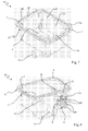
- Figs. 7, 8 and 9 show different perspective views of a sump 10 for a household appliance, in particular for a dishwasher, according to the present invention.
- Said sump 10 comprises a container C adapted to contain a liquid, a sensor assembly 11 comprising a sensor element 1 provided with a light transmitter T adapted to generate a light beam, and a light receiver R adapted to receive said light beam, in particular said sensor element 1 being fitted on a printed circuit CS through respective hooking elements.
- the sump 10 also comprises an optical element 12, in particular made of a transparent material, adapted to affect the light beam emitted by the light transmitter T depending on the content of said container C.
- the term "transparent” is used to indicate transparency to the radiation or to the wave length of said light beam, which may even be invisible, emitted by the light transmitter; for example, let us consider an emission within the infrared spectrum or a laser beam. Consequently, even materials seemingly not transparent or even opaque may turn out to be transparent to said light beam.
- said optical element 12 is built in or fitted on said container C, said optical element 12 comprising a prism which may be either solid or hollow.
- the optical element 12 is projecting from an inner surface 13 of the container C; alternatively, the optical element 12 may be so provided as to be recessed in said inner surface 13 of the container C, i.e. the optical element 12 may have different shapes than described herein by way of non-limiting example.
- the optical element 12 is adapted to reflect the light beam in different ways depending on the content of said container C.
- the container C contains a liquid which level is higher than the level where the sensor assembly 11 is fitted, the light beam emitted by the light transmitter T will be absorbed or deflected by the liquid, and therefore it will not reach the light receiver R.
- the light beam emitted by the light transmitter T will be reflected by the optical element 12 and will reach the light receiver R at least partially.
- the optical element 12 preferably comprises a plate, preferably a strip, being substantially flat and made of or obtained from a transparent material, i.e. it preferably comprises at least a portion of the surface 13 of the container C.
- Said optical element 12 may advantageously be manufactured separately and then secured to said container C or sump 10, e.g. by using engaging means and an interposed sealing element, or else be welded or glued thereto.
- the container C is wholly or partially made of or obtained from a transparent material, and the optical element 12 is preferably made of the same transparent material.
- the optical element 12 has an elongated shape and extends in a substantially vertical direction relative to the installation or extension plane of said container C.
- the optical element 12 it is possible to use, for example, a plurality of sensor assemblies 11, in particular at least two sensor assemblies 11, in order to be able to detect two distinct filling levels of the container C of the sump 10, or else a single sensor assembly 11 can be easily located at different heights both during the assembling operations and during any subsequent level calibration or adjustment.
- the sensor assembly 11 and/or the sump 10 may advantageously be fitted with respective coupling elements (not shown) adapted to allow for a fine or precise positioning.
- respective coupling elements not shown
- a product made of a thermoplastic material may undergo dimensional variations due to shrinkage occurring during the cooling step.
- the optical element 12 may have an elongated shape extending in a substantially horizontal direction relative to the installation or extension plane of said container C; this arrangement allows, for example, to perform a double check of the same filling level of the container C of the sump 10.
- the optical element 12 should preferably be provided with an elongated shape extending substantially for the whole length or width or height of said surface 13 of the container C or for a significant part thereof; such an arrangement of the optical element 12 facilitates the moulding process and also makes it easier to position the sensor assembly 11 for detecting a predetermined liquid level in the sump 10.
- sump 10 for a household appliance in particular for a dishwasher, may comprise a plurality of hydraulic ducts or fittings, in particular:
- Some portions of said sump 10 may advantageously be so shaped as to provide portions of other devices as well, e.g. pumps or solenoid valves or diverting valves or actuators or other types of sensors.
- the sump 10 comprises an edge 17 having a pair of raised walls 18, 19 adapted to provide an outer seat adapted to house a gasket (not shown in the drawings) and/or adapted to be welded to the lower portion of the wash tub V of a washing machine, in particular a dishwasher.
- Said sump 10, in particular the edge 17 of said sump 10, may also comprise additional fastening means for fixing it to a machine for washing and/or to its wash tub V, e.g. a plurality of holes F adapted to accommodate screws or similar fastening means, not shown in the drawings.
- Figs. 10 and 11 show a side view and a top view, respectively, of the sump 10, while Fig. 12 shows a sectional view of the sump 10 according to the axis B-B of Fig. 11.
- the sump 10 comprises a seat or casing S adapted to accommodate the sensor assembly 11, which comprises said printed circuit CS provided with electric contacts for the electric connection of said sensor assembly 11 to an electric wiring or to an electric connector.
- the seat or casing S may be made hermetic, e.g. filled with resin, or overmoulded with thermoplastic material, or closed with a welded or glued cover.
- the printed circuit CS is so shaped as to provide, through its traces, a male electric connector which can be coupled to a connector CON of the wiring of the machine for washing.
- said printed circuit CS may comprise polarization means adapted to prevent an inverse connection of the sensor assembly 11.
- Figs. 13 and 14 show some detailed views of the sensor assembly 11, in particular according to different positionings relative to the sump 10.
- the seat or casing S of the sump 10 comprises a plurality of fixing seats, in particular a first pair of fixing seats 20A and a second pair of fixing seats 20B, the first pair of fixing seats 20A being located higher than the second pair of fixing seats 20B.
- said fixing seats 20A, 20B allow to assemble the sensor assembly 11 in at least two different and preferably predefined positions.
- the fixing seats 20A, 20B consist of apertures adapted to accommodate fixing means, e.g. screws 20C.
- the seat S of the sump 10 may comprise a larger number of pairs of fixing seats 20A, 20B, as well as that said pairs of fixing seats 20A, 20B may also be provided as vertical or horizontal slots, so that the sensor assembly 11 can be assembled on said adjustable position.
- Fig. 15 shows a sectional top view of the sensor assembly 11 and of a portion of the sump 10
- Figs. 16 and 17 respectively show a side view and a front view of the sensor assembly 11, connected to said wiring CON.
- the transmitter T and the receiver R make up an optical detection pair, preferably for detecting a liquid level in the sump 10.
- Said optical detection pair faces the optical element 12, which, as aforementioned, is adapted to affect the light beam emitted by the light transmitter T in different ways depending on the content of the sump 10.
- the optical element 12 reflects the light beam, so that it reaches the light receiver R at least partially.
- the sump 10 may comprise at least two optical detection pairs, preferably for detecting two or more different liquid levels in the sump 10; said at least two optical detection pairs may be supported by the same sensor assembly 11 or else by at least two respective sensor assemblies 11.
- the sump 10 may be so provided as to comprise an electric or electronic module comprising said light transmitter T and said light receiver R.
- said module may also comprise an electronic processor, preferably a microcontroller, connected to said light transmitter T and to said light receiver R; in addition, said module typically and advantageously comprises a printed circuit provided with electric contacts for the electric connection of said module to an electric wiring or to an electric connector, of the male, female or mixed type, of the machine of washing.
- an electronic processor preferably a microcontroller
- Figs. 18 to 21 show different views of a first embodiment example of a component 100' adapted to be at least partially applied to or associated with a sump 10' of a household appliance, in particular a dishwasher, adapted to contain at least a portion of a wash liquid, wherein said sump 10' comprises a container C' adapted to contain said liquid.
- the component 100' comprises:
- the component 100' is adapted to detect at least one liquid level in said container C'.
- the light transmitter T' and the light receiver R' make up an optical pair 111' and face the optical element 112', which is adapted to reflect or deflect said light beam differently depending on the content of the container C'.
- the optical element 112' reflects or deflects the light beam emitted by the light transmitter T', so that it reaches the light receiver R' at least partially.
- said optical element 112' is a solid or an at least partially hollow prism, and is projecting (as shown in the drawings) or recessed relative to an outer surface or casing of the component 100'.
- Said optical element 112' may also be so provided as to comprise a plate, preferably a strip, being substantially flat and made of a transparent material.
- the optical element 112' preferably comprises at least one substantially flat wall, in particular facing the light transmitter T' and the light receiver R'.
- the component 100' comprises a body or casing 110' adapted to be located at least partially inside said container C' of the sump 10' through an aperture being present in at least one of the surfaces 13' of the sump 10'.
- Said optical element 112' may advantageously be manufactured separately and then secured to said body or casing 110', e.g. by using engaging means and an interposed sealing element, or else be welded or glued thereto.
- said body or casing 110' is at least partially made of a transparent material, which forms at least a portion of said optical element 112'.
- the body or casing 110' may have a substantially hollow shape, e.g. cylindrical or prismatic.
- the optical element 112', located in or on said body or casing 110', is preferably arranged in a direction being substantially parallel to the axis of said body or casing 110', or in a direction being substantially perpendicular to the surface 13' whereto the optical element 112' is secured.
- the optical element 112' may also be provided or located in another position (not shown) in or on said body or casing 110', for example on an end surface 118'; the optical element 112' may therefore be arranged in a direction being substantially perpendicular to the axis of said body or casing 110', or in a direction being substantially parallel to the surface 13' whereto the optical element 112' is secured, or else parallel or perpendicular to at least a portion of the bottom surface of the sump.
- the sump 10' for a household appliance, in particular for a dishwasher, according to the present invention is substantially made like the sump 10 described previously; consequently, Figs. 18, 19, 20 e 21 will include the same reference numbers already used for the sump 10, with the addition of an apostrophe.
- At least one surface 13' of the sump 10' has an aperture through which the body or casing 110' of the component 100' is inserted, so that it can be positioned at least partially inside said container C' of the sump 10'.
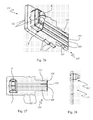
- Said surface 13' comprises a plurality of retaining elements 30', adapted to cooperate with coupling or engaging means 113' being present on the component 100' in order to couple said component 100' to the sump 10'.
- said retaining elements 30' of the sump 10' comprise reliefs 30'; said reliefs 30' substantially have an "L" shape, in that they comprise a first portion 30'A extending from the surface 13' of the sump 10' and a second portion 30'B extending from said first portion 30'A.
- Figs. 22, 23 and 24 provide a better view of the coupling or engaging means of the component 100', which comprise lugs 113'.
- the component 100' advantageously comprises a plurality of grip elements 114', which make it easier to turn the component 100' and, consequently, to couple it to the sump 10', said grip elements 114' being suitable for being handled manually or for being coupled to an installation tool.
- the component 100' may also be coupled to the sump 10' in other ways, e.g. through means adapted to allow it to be applied to said sump 10' by screwing or welding or fitting or glueing; preferably, said coupling is provided through means which allow said component 100' to be removed, e.g. in order to facilitate maintenance operations, but said coupling may however be advantageously provided through means which make said component 100' irremovable.
- Fig. 25 shows an alternative system for obtaining a secure coupling between the component 100' and the sump 10', in particular through a snap-type or quick fitting in a substantially linear direction.
- the above-mentioned figure clearly shows the L-shaped reliefs 30', which comprise the first portion 30'A extending from the surface 13' of the sump 10' and the second portion 30'B extending from said first portion 30'A.
- the component 100' comprises engaging means, in particular elastic tongues 115', adapted to cooperate with the reliefs 30' for fixing the component 100' to the sump 10'.
- said elastic tongues 115' comprise an engaging projection or seat 116' adapted to be coupled to and/or abutted on the second portion 30'B of the reliefs 30'.
- the component 100' also comprises sealing means, in particular a gasket 117', which prevents the liquid from leaking out of the container C' when the component 100' has been secured to the sump 10'.
- Said body or casing 110', 110" may also comprise said coupling or engaging means 113', 115', 116', preferably provided in one piece, in particular by moulding a thermoplastic material.
- the component 100' additionally comprises a support and/or fixing element for the optical pair 111', comprising the light transmitter T' and the light receiver R'; said support and/or fixing element typically comprises a printed circuit CS', in particular as shown in Figs. 26 to 28.
- the printed circuit CS' comprises or provides an electric connector 119', e.g. consisting of electric contacts or terminals 120', adapted to be connected or wired electrically to the user apparatus, in particular for supplying power to the optical pair 111' or to other elements of the component 100' and for the detection and transmission of the respective signal Vout.
- an electric connector 119' e.g. consisting of electric contacts or terminals 120', adapted to be connected or wired electrically to the user apparatus, in particular for supplying power to the optical pair 111' or to other elements of the component 100' and for the detection and transmission of the respective signal Vout.
- the printed circuit CS' is so shaped as to comprise two seats or two slots 121', located at said electric terminals 120', for coupling the printed circuit CS' to a respective electric connector CON or to the electric wiring of the user apparatus, typically a household appliance, said electric connector CON of the wiring being fitted with respective engaging means adapted to be engaged into said seats 121'.
- the printed circuit CS' has a plurality of steps or reliefs 122', adapted to be latched to and/or abutted on respective means being present inside the body or casing 110' or inside the component 100', in particular in order to provide an anti-removal device and to ensure an accurate positioning of the optical pair 112' inside the component 100', in particular relative to the body or casing 110' and/or to the optical element 112'.
- the component 100' also comprises coupling means, adapted to provide a univocal coupling between said printed circuit CS' and an electric connector CON or the electric wiring of the user apparatus, typically a household appliance.
- the printed circuit CS' is so shaped as to comprise said coupling means, in particular at least one polarization seat 123', adapted to cooperate with respective means provided on said electric connector CON or with the electric wiring of the user apparatus.
- Said optical sensor 111' and/or the printed circuit CS' may be advantageously protected, i.e. sealed inside the body or casing 110'; the possible presence of holes (not shown) in the printed circuit CS' facilitates the distribution of insulating or filling material, such as resin poured into a casing seat, such as said body or casing 110', wherein the printed circuit CS', with its electric and/or electronic components, is inserted.
- Fig. 29 shows a further possible embodiment of the coupling means between said printed circuit CS' and an electric connector or the electric wiring of the user apparatus, typically a household appliance.
- the component 100' comprises a connector 130' of a known or available type, e.g. of the type commonly defined as "Rast 2.5".
- the connector 130' is made of an electrically insulating thermoplastic material, and is built in or adapted to be coupled to said casing 110', possibly engaged with the end portion of the printed circuit CS', e.g. through hooks or projecting elements being present inside said connector 130', which engage in respective holes or seats of the printed circuit CS'; it should also be considered that said printed circuit CS is coupled to the component 100' through said reliefs or steps 122'.
- Said connector 130' comprises engaging elements 131' to be coupled to an electric connector CON' of the electric wiring of the user apparatus; in particular, said electric connector CON' comprises suitable seats 141' adapted to house the engaging elements 131'.
- the connector 130' comprises first polarization means, in particular seats 132' adapted to prevent an improper connection to the electric wiring.
- the electric connector CON' of the wiring from which three electric wires 150' come out, comprises second polarization means or reliefs 142' adapted to be coupled to the seats 132' of said connector 130' in order to ensure a univocal mechanic and electric coupling between said wiring and the component 100'.
- Said polarization means 132', 142' are adapted to prevent an inverse connection of the component 100'.
- the connector 130' may be an element being distinct from said component 100' and may be fitted with external engaging elements, adapted to be coupled to the component 100' so as to provide a known or commonly available adapter, e.g. of the type defined as "Rast 2.5".
- the transmitter T' and the receiver R' make up an optical pair 111', preferably for detecting at least one liquid level in the sump 10'; said optical pair 111' may be assembled or built in a single electronic component 1 or else it may consist of a plurality of distinct electronic components assembled on a single electronic circuit.
- the component 100' may comprise at least two optical detection pairs, preferably for detecting two different liquid levels, said at least two optical pairs using the same optical element 112'; alternatively, the component 100' may be so provided that the light transmitter T' and the light receiver R' can be fitted on at least two different and preferably predefined positions.
- the sump 10' may be so provided that said component 100' is assembled on an adjustable position, said position being preferably angular, and/or that three or four different and preferably predefined positions are available, said positions being preferably angular and displaced by 90°; said angular position may, for example, be obtained by turning the component 100' about its axis.
- sump 10' and/or the component 100' may be so provided as to comprise an electric or electronic module comprising said light transmitter T' and/or said light receiver R'.
- said module may comprise an electronic processor, preferably a microcontroller, connected to said light transmitter T' and to said light receiver R'; in addition, said module may comprise a suitable connector or a printed circuit provided with electric contacts for the electric connection of said module to an electric wiring or to an electric connector, of the male, female or mixed type, of the machine of washing.
- Said electric or electronic module may also be adapted to control the component 100' or the sump 10', e.g. as a local controller, by operating as an interface to the control system of the household appliance, not shown.
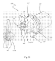
- the above-described component 100' may be so modified as to obtain a component, designated by reference number 100" in Figs. 30 and 31, adapted to be at least partially applied to or associated with a sump of a household appliance, in particular a washing machine, typically a dishwasher, said sump being adapted to contain at least a portion of a wash liquid and comprising a container adapted to contain said liquid.
- the component 100 comprises:
- the component 100" is adapted to detect two distinct liquid levels in the sump container, in particular a first load level and a second safety level, e.g. said second safety level allowing to indicate the presence of an excessive quantity of liquid in the container of said sump.
- said component 100' would be adapted to perform a double check of the same liquid level in the sump container, e.g. in order to prevent any malfunctioning due to dirt and/or limescale deposits on one of said optical elements 112A" and 112B".
- Said optical elements 112A" and 112B" are either solid or hollow prisms, and are either projecting or recessed relative to an outer surface of the component 100".
- said optical elements 112A" and 112B" comprise one plate each or a single common plate, preferably a strip, being substantially flat and made of a transparent material.
- the component 100' comprises a body or casing 110" adapted to be located wholly or partially inside the container of the sump.
- the body or casing 110" has a substantially an oval section; more in general, said section may have an elongated shape and preferably a perimeter with no sharp edges, i.e. with at least partially rounded perimeter portions, in order to ensure a good seal in respect to a sealing element 117" of the sensor 100".
- the sump seat wherein said component is to be housed and/or inserted shall have a complementary shape to that of the body or casing 110", e.g. an oval or elongated section, preferably with no sharp edges and/or being at least partially rounded.
- said body or casing 110" is at least partially made of a transparent material, and said optical elements 112A" and 112B" are located in or on said body or casing 110" and are preferably made of the same transparent material.
- optical elements 112A" and 112B" are located in or on said body or casing 110" and are arranged in a direction being substantially parallel to the axis of said body or casing 110", i.e. perpendicular to an end surface 118" of the body or casing 110".
- the coupling between the component 100" and the sump of the household appliance preferably takes place through a snap-type fitting or a preferably quick coupling, as described with reference to Fig. 25.
- the component 100" comprises engaging means as well, in particular elastic tongues 115" provided with projections 116", for securing the component 100" to the sump.
- the component 100" comprises sealing means, in particular a gasket 117".
- Said body or casing 110 i.e. said component 100
- Said body or casing 110 is shown as having a mostly oval section and an elongated shape; however, said shape or section may be different, e.g. circular or squared in some areas.
- the section or profile preferably has no sharp edges in the area corresponding to said sealing means 117", i.e. the profile is at least partially curved.
- the component 100" also comprises a support and/or fixing element for the first optical pair 111A" and the second optical pair 111B", said support and/or fixing element typically comprising a printed circuit CS", as shown in particular in Figs. 32 and 33.
- the printed circuit CS" comprises or provides an electric connector 119", e.g. consisting of a plurality of electric contacts or terminals 120", adapted to be connected or wired electrically to the user apparatus, in particular for supplying power to the optical pairs 111A", 111B" and/or to other elements of the component 100" as well as for the detection and transmission of the signals Vout.
- an electric connector 119 e.g. consisting of a plurality of electric contacts or terminals 120"
- adapted to be connected or wired electrically to the user apparatus in particular for supplying power to the optical pairs 111A", 111B" and/or to other elements of the component 100" as well as for the detection and transmission of the signals Vout.
- the printed circuit CS" is essentially shaped like the one described with reference to Figs. 26, 27, 28, in that it comprises:
- the sensor assembly 11 and/or the component 100', 100" may be so provided as to comprise a number of light transmitters T, T', T" being different from the number of light receivers R, R', R", e.g. a single light transmitter T, T', T" and a plurality of light receivers R, R', R".
- the optical elements 12', 112', 112" may also have a different shape from the one previously described, e.g. a shape adapted to deflect a single light beam toward different light receivers R, R', R" depending on different levels of the liquid being present in the containers C, C'.
- the sensor assembly 11 may be so provided as to comprise a transparent casing or a casing which is open at one end. Such a version would allow to assemble the sensor assembly 11 very easily into the seat or casing S of the sump 10 so that it faces the optical element 12.
- the polarization means of the sensor assembly 11 and/or of the component 100', 100" may be so provided that each connector has a different coding, i.e. a different arrangement of the coding seats and reliefs, so as to prevent said sensor assembly 11 and/or said component 100', 100" from being connected to a wrong connector possibly being present in the household appliance.
- thermoplastic elements e.g. between parts of the sump, such as prism on the sump or component on the sump, or between parts of the component, etc.
- a known type of welding which is particularly suited to the present invention is laser welding between thermoplastic elements, e.g. welding a first thermoplastic material being transparent to the laser beam to a second material which heats up when hit by said laser beam, in order to obtain a local melting and joint of said two thermoplastic materials.
- Another innovative aspect of the present invention relates to a calibration and/or adjustment method; the general idea at the basis of said method can be applied to a component (according to the present invention) adapted to detect at least one liquid level in a container, as well as to a sump (according to the present invention) comprising a container and adapted to detect at least one liquid level in said container. Said method can be carried out either during the production stage or during the installation stage.
- the component comprises at least one body, one light transmitter, one light receiver and one optical element; according to the calibration and/or adjustment method, the position of the light transmitter and/or of the light receiver and/or of the optical element is changed relative to the component body.
- the position change may be made by acting on coupling elements adapted to allow for at least one fine or precision positioning, in particular by turning at least one calibration and/or adjustment screw; note that these coupling elements are not shown in the drawings.
- the position of the light transmitter and the position of the light receiver are both changed preferably to the same extent and preferably simultaneously. If the light transmitter and the light receiver are supported by and/or fixed to a support and/or fixing element, typically a printed circuit, the change in the positions of the light transmitter and of the light receiver may advantageously be obtained by changing the position of the support and/or fixing element.
- a support and/or fixing element typically a printed circuit
- the sump comprises a container, a light transmitter, a light receiver and an optical element; according to the calibration and/or adjustment method, the position of the light transmitter and/or of the light receiver and/or of the optical element is changed relative to the container of the sump.
- the container is filled with liquid up to the level to be detected, after which the position is changed accordingly.
- the position change may be made by acting on coupling elements adapted to allow for at least one fine or precision positioning, in particular by turning at least one calibration and/or adjustment screw; note that these coupling elements are not shown in the drawings.
- the position of the light transmitter and the position of the light receiver are both changed preferably to the same extent and preferably simultaneously.
- the change in the positions of the light transmitter and of the light receiver may advantageously be obtained by changing the position of the support and/or fixing element.
- the light transmitter, the light receiver and the optical element are comprised or built in a component, the change in the position of the light transmitter, the light receiver and the optical element is obtained by changing the position of said component; said change of position may be at least partially angular and/or linear.
- said component provides an optical tool for detecting and controlling the level of a liquid in a household washing machine, in particular a dishwasher, which can be applied effectively and efficiently in particular to the sump of the machine for washing.
- said sump fitted with an optical sensor assembly provides an effective and efficient solution for use in machines for washing.
Landscapes
- Physics & Mathematics (AREA)
- Electromagnetism (AREA)
- Thermal Sciences (AREA)
- Fluid Mechanics (AREA)
- General Physics & Mathematics (AREA)
- Engineering & Computer Science (AREA)
- Textile Engineering (AREA)
- Measurement Of Levels Of Liquids Or Fluent Solid Materials (AREA)
- Washing And Drying Of Tableware (AREA)
Applications Claiming Priority (1)
| Application Number | Priority Date | Filing Date | Title |
|---|---|---|---|
| IT000856A ITTO20050856A1 (it) | 2005-12-06 | 2005-12-06 | Componente per elettrodomestico, in particolare per lavastoviglie, e pozzetto per elettrodomestico, in particolare per lavastoviglie, che lo utilizza |
Publications (2)
| Publication Number | Publication Date |
|---|---|
| EP1795110A2 true EP1795110A2 (fr) | 2007-06-13 |
| EP1795110A3 EP1795110A3 (fr) | 2014-08-20 |
Family
ID=37946401
Family Applications (1)
| Application Number | Title | Priority Date | Filing Date |
|---|---|---|---|
| EP06125307.6A Withdrawn EP1795110A3 (fr) | 2005-12-06 | 2006-12-04 | Composant pour appareil électroménager, en particulier pour un lave-vaisselle, et collecteur pour appareil électroménager, en particulier pour un lave-vaisselle, utilisant celui-ci |
Country Status (3)
| Country | Link |
|---|---|
| US (1) | US7820995B2 (fr) |
| EP (1) | EP1795110A3 (fr) |
| IT (1) | ITTO20050856A1 (fr) |
Cited By (2)
| Publication number | Priority date | Publication date | Assignee | Title |
|---|---|---|---|---|
| ITTO20090231A1 (it) * | 2009-03-26 | 2010-09-27 | Elbi Int Spa | Apparecchio rilevatore destinato a rilevare il livello di una sostanza liquida, in gel o in polvere contenuta in un recipiente |
| EP4036534B1 (fr) * | 2016-12-12 | 2024-01-31 | Illinois Tool Works, Inc. | Capteur optique de niveau de récipient amovible d'aide au lavage |
Families Citing this family (16)
| Publication number | Priority date | Publication date | Assignee | Title |
|---|---|---|---|---|
| TW201009636A (en) * | 2008-08-18 | 2010-03-01 | Gemtek Technology Co Ltd | Electronic device for preventing improper disassembling |
| NL2010203C2 (en) * | 2013-01-30 | 2014-08-04 | Opw Fluid Transfer Group Europ B V | Optical liquid level detection sensor and liquid overfill prevention system comprising such sensor. |
| US20170152621A1 (en) * | 2015-12-01 | 2017-06-01 | Whirlpool Corporation | Laundry treating appliance |
| US10487432B2 (en) | 2015-12-01 | 2019-11-26 | Whirlpool Corporation | Laundry treating appliance |
| US10053808B2 (en) | 2015-12-01 | 2018-08-21 | Whirlpool Corporation | Laundry treating appliance |
| US10125446B2 (en) | 2015-12-01 | 2018-11-13 | Whirlpool Corporation | Laundry treating appliance |
| US10036114B2 (en) | 2015-12-01 | 2018-07-31 | Whirlpool Corporation | Laundry treating appliance |
| US10273623B2 (en) | 2016-09-22 | 2019-04-30 | Midea Group Co., Ltd. | Laundry washing machine incorporating distance sensor |
| DE102018209076A1 (de) * | 2018-06-07 | 2019-12-12 | BSH Hausgeräte GmbH | Geschirrspülmaschine, Verfahren zum Betreiben einer Geschirrspülmaschine und Computerprogrammprodukt |
| DE102018115059A1 (de) * | 2018-06-22 | 2019-12-24 | Miele & Cie. Kg | Wäschetrockner oder Waschtrockner |
| DE102018115065A1 (de) * | 2018-06-22 | 2019-12-24 | Miele & Cie. Kg | Dampferzeuger für ein Haushaltsgerät, insbesondere Dampfgarer |
| KR20220011903A (ko) | 2020-07-22 | 2022-02-03 | 삼성전자주식회사 | 식기 세척기 |
| US20230020473A1 (en) | 2021-07-15 | 2023-01-19 | Fortune Brands Water Innovations LLC | Sump pump system, including sump pump monitor and application |
| WO2023288077A1 (fr) * | 2021-07-15 | 2023-01-19 | Fortune Brands Water Innovations LLC | Système de pompe de puisard, comprenant un blindage détecteur de niveau d'eau |
| US12196447B2 (en) * | 2023-05-25 | 2025-01-14 | Helpful Innovations, Llc | Reservoir and pump system |
| CN117481566B (zh) * | 2024-01-02 | 2024-04-12 | 珠海格力电器股份有限公司 | 一种洗碗机水量检测方法、装置、洗碗机和存储介质 |
Family Cites Families (13)
| Publication number | Priority date | Publication date | Assignee | Title |
|---|---|---|---|---|
| US2669323A (en) * | 1952-08-04 | 1954-02-16 | Fountron Corp | Food service system and means therefor |
| US3279481A (en) * | 1964-08-31 | 1966-10-18 | Gen Motors Corp | Dishwasher with speed control means |
| US3870417A (en) * | 1973-07-17 | 1975-03-11 | Whirlpool Co | Sensor for dishwasher |
| DE4242927B4 (de) * | 1992-12-18 | 2004-03-18 | Bauknecht Hausgeräte GmbH | Optischer Sensor |
| US5329951A (en) * | 1993-05-10 | 1994-07-19 | Jones Colin H | Cylinder head cleaning machine |
| US6519034B1 (en) * | 1998-12-16 | 2003-02-11 | Honeywell International Inc. | Oil quality sensor |
| DE19945925A1 (de) * | 1999-09-24 | 2001-03-29 | Bsh Bosch Siemens Hausgeraete | Wasserführendes Haushaltgerät |
| DE20022433U1 (de) * | 2000-04-29 | 2001-09-06 | Whirlpool Co | Sensor zum Messen der Eigenschaften eines gasförmigen oder flüssigen Mediums |
| DE50210345D1 (de) * | 2002-01-31 | 2007-08-02 | Emz Hanauer Gmbh & Co Kgaa | Trübungssensor mit Temperaturerfassung für Haushaltsgeräte |
| DE10208214B4 (de) * | 2002-02-26 | 2004-09-30 | BSH Bosch und Siemens Hausgeräte GmbH | Vorrichtung zur Überprüfung der Belagbildung und wasserführendes Gerät |
| KR20060024597A (ko) * | 2004-09-14 | 2006-03-17 | 엘지전자 주식회사 | 식기세척기의 구조 |
| US7836535B2 (en) * | 2004-09-14 | 2010-11-23 | Lg Electronics Inc. | Dishwasher and a method for controlling the same |
| WO2007143047A1 (fr) * | 2006-06-01 | 2007-12-13 | Ecolab Inc. | Capteur fluorométrique uv et son procédé d'utilisation |
-
2005
- 2005-12-06 IT IT000856A patent/ITTO20050856A1/it unknown
-
2006
- 2006-12-04 EP EP06125307.6A patent/EP1795110A3/fr not_active Withdrawn
- 2006-12-06 US US11/567,248 patent/US7820995B2/en not_active Expired - Fee Related
Cited By (6)
| Publication number | Priority date | Publication date | Assignee | Title |
|---|---|---|---|---|
| ITTO20090231A1 (it) * | 2009-03-26 | 2010-09-27 | Elbi Int Spa | Apparecchio rilevatore destinato a rilevare il livello di una sostanza liquida, in gel o in polvere contenuta in un recipiente |
| WO2010109416A1 (fr) * | 2009-03-26 | 2010-09-30 | Elbi International S.P.A. | Appareil pour détecter le niveau d'un liquide, d'un gel ou d'une poudre dans un récipient |
| CN102365533A (zh) * | 2009-03-26 | 2012-02-29 | 埃尔比国际有限公司 | 用来检测液体、胶冻或粉末在容器中的水平高度的设备 |
| US8559022B2 (en) | 2009-03-26 | 2013-10-15 | Elbi International S.P.A. | Sensor apparatus intended to detect the level of a liquid, gel or power substance contained in a receptacle |
| CN102365533B (zh) * | 2009-03-26 | 2014-03-19 | 埃尔比国际有限公司 | 用来检测液体、胶冻或粉末在容器中的水平高度的设备 |
| EP4036534B1 (fr) * | 2016-12-12 | 2024-01-31 | Illinois Tool Works, Inc. | Capteur optique de niveau de récipient amovible d'aide au lavage |
Also Published As
| Publication number | Publication date |
|---|---|
| ITTO20050856A1 (it) | 2007-06-07 |
| US20070144564A1 (en) | 2007-06-28 |
| EP1795110A3 (fr) | 2014-08-20 |
| US7820995B2 (en) | 2010-10-26 |
Similar Documents
| Publication | Publication Date | Title |
|---|---|---|
| US7820995B2 (en) | Component for a household appliance, in particular for a dishwasher, and sump for a household appliance, in particular for a dishwasher, using it | |
| CA2645370C (fr) | Capteur de fuite d'un liquide | |
| US8994812B2 (en) | Optical sensor for detecting the liquid level in a container, in particular for a removable container for an electric household appliance and associated lens and method | |
| EP2325600A1 (fr) | Dispositif d'induction de détection de distance | |
| KR101981679B1 (ko) | 식기세척기 및 식기세척기의 센싱 모듈 | |
| CN102341695B (zh) | 用于家用电器的浊度传感器 | |
| KR20030066373A (ko) | 가전제품용 센서와 가전제품용 센서의 하우징 | |
| CN101720428A (zh) | 传感器 | |
| US20050199792A1 (en) | Optical sensor | |
| US7265289B2 (en) | Electronic module | |
| EP1245713A1 (fr) | Capteur pour mesure des propriétés d'un milieu gazeux ou liquide | |
| EP3132080B1 (fr) | Capteur de pression à siphon incorporé | |
| EP2332456B1 (fr) | Accessoire integré pour l'alimentation une machine lave-vaisseille | |
| US9861248B2 (en) | Optical sensor for water-air detection | |
| ES2605361T3 (es) | Sensor para la medición de turbiedad y temperatura | |
| CN101909506B (zh) | 用于使用水的器具的多功能转换器 | |
| EP0805617B1 (fr) | Panneau de raccordement muni d'un filtre d'interférence en particulier pour appareils électroménagers | |
| EP2062519B1 (fr) | Lave-vaisselle avec système de sécurité anti-écoulement | |
| CN220340402U (zh) | 一种距离感应装置及卫浴产品 | |
| EP0048607A1 (fr) | Détecteur de niveau pour machines à laver | |
| KR101635427B1 (ko) | 다기능 수중펌프 | |
| CN223485256U (zh) | 适用于洗涤剂分配器的液位检测组件及洗涤剂分配器 | |
| CN115369620A (zh) | 一种储液盒的密封盖结构、投放装置及衣物处理设备 | |
| CN219532189U (zh) | 一种液位计 | |
| CN113633240A (zh) | 一种盒组件及具有盒组件的洗碗机 |
Legal Events
| Date | Code | Title | Description |
|---|---|---|---|
| PUAI | Public reference made under article 153(3) epc to a published international application that has entered the european phase |
Free format text: ORIGINAL CODE: 0009012 |
|
| AK | Designated contracting states |
Kind code of ref document: A2 Designated state(s): AT BE BG CH CY CZ DE DK EE ES FI FR GB GR HU IE IS IT LI LT LU LV MC NL PL PT RO SE SI SK TR |
|
| AX | Request for extension of the european patent |
Extension state: AL BA HR MK YU |
|
| RIC1 | Information provided on ipc code assigned before grant |
Ipc: A47L 15/42 20060101AFI20140220BHEP Ipc: D06F 39/08 20060101ALI20140220BHEP |
|
| PUAL | Search report despatched |
Free format text: ORIGINAL CODE: 0009013 |
|
| AK | Designated contracting states |
Kind code of ref document: A3 Designated state(s): AT BE BG CH CY CZ DE DK EE ES FI FR GB GR HU IE IS IT LI LT LU LV MC NL PL PT RO SE SI SK TR |
|
| AX | Request for extension of the european patent |
Extension state: AL BA HR MK RS |
|
| RIC1 | Information provided on ipc code assigned before grant |
Ipc: A47L 15/42 20060101AFI20140714BHEP Ipc: D06F 39/08 20060101ALI20140714BHEP |
|
| AKY | No designation fees paid | ||
| AXX | Extension fees paid |
Extension state: RS Extension state: AL Extension state: MK Extension state: HR Extension state: BA |
|
| REG | Reference to a national code |
Ref country code: DE Ref legal event code: R108 |
|
| REG | Reference to a national code |
Ref country code: DE Ref legal event code: R108 Effective date: 20150429 |
|
| STAA | Information on the status of an ep patent application or granted ep patent |
Free format text: STATUS: THE APPLICATION IS DEEMED TO BE WITHDRAWN |
|
| 18D | Application deemed to be withdrawn |
Effective date: 20150221 |