EP1795330A2 - Procédé et dispositif pour le contrôle de l'activation de surface de pièces en matière plastique - Google Patents
Procédé et dispositif pour le contrôle de l'activation de surface de pièces en matière plastique Download PDFInfo
- Publication number
- EP1795330A2 EP1795330A2 EP06023019A EP06023019A EP1795330A2 EP 1795330 A2 EP1795330 A2 EP 1795330A2 EP 06023019 A EP06023019 A EP 06023019A EP 06023019 A EP06023019 A EP 06023019A EP 1795330 A2 EP1795330 A2 EP 1795330A2
- Authority
- EP
- European Patent Office
- Prior art keywords
- temperature
- component
- determined
- flaming
- minimum temperature
- Prior art date
- Legal status (The legal status is an assumption and is not a legal conclusion. Google has not performed a legal analysis and makes no representation as to the accuracy of the status listed.)
- Granted
Links
Images
Classifications
-
- B—PERFORMING OPERATIONS; TRANSPORTING
- B29—WORKING OF PLASTICS; WORKING OF SUBSTANCES IN A PLASTIC STATE IN GENERAL
- B29C—SHAPING OR JOINING OF PLASTICS; SHAPING OF MATERIAL IN A PLASTIC STATE, NOT OTHERWISE PROVIDED FOR; AFTER-TREATMENT OF THE SHAPED PRODUCTS, e.g. REPAIRING
- B29C59/00—Surface shaping of articles, e.g. embossing; Apparatus therefor
- B29C59/08—Surface shaping of articles, e.g. embossing; Apparatus therefor by flame treatment ; using hot gases
-
- C—CHEMISTRY; METALLURGY
- C08—ORGANIC MACROMOLECULAR COMPOUNDS; THEIR PREPARATION OR CHEMICAL WORKING-UP; COMPOSITIONS BASED THEREON
- C08J—WORKING-UP; GENERAL PROCESSES OF COMPOUNDING; AFTER-TREATMENT NOT COVERED BY SUBCLASSES C08B, C08C, C08F, C08G or C08H
- C08J7/00—Chemical treatment or coating of shaped articles made of macromolecular substances
- C08J7/12—Chemical modification
-
- C—CHEMISTRY; METALLURGY
- C08—ORGANIC MACROMOLECULAR COMPOUNDS; THEIR PREPARATION OR CHEMICAL WORKING-UP; COMPOSITIONS BASED THEREON
- C08J—WORKING-UP; GENERAL PROCESSES OF COMPOUNDING; AFTER-TREATMENT NOT COVERED BY SUBCLASSES C08B, C08C, C08F, C08G or C08H
- C08J2323/00—Characterised by the use of homopolymers or copolymers of unsaturated aliphatic hydrocarbons having only one carbon-to-carbon double bond; Derivatives of such polymers
- C08J2323/02—Characterised by the use of homopolymers or copolymers of unsaturated aliphatic hydrocarbons having only one carbon-to-carbon double bond; Derivatives of such polymers not modified by chemical after treatment
Definitions
- the invention relates to a method and a device for controlling the surface activation of a plastic component, in particular of a polyolefin by flaming with a burner.
- plastics in particular polyolefins, have a low surface tension, which leads to an insufficient adhesion, for example, of a lacquer to a polyolefin component. It is therefore carried out a surface activation of polyolefin components by flaming with a burner. As a result, various, predominantly oxygen-containing functional groups are generated on the component surface, which cause an increase in the surface energy.
- the flame is determined essentially by the parameters: distance of the flame from the component, duration of the action of the flame, mixing ratio of fuel gas / air and throughput of the fuel gas / air mixture.
- test inks DIN 53 364. These are liquids of known surface tension. Becomes a liquid with a certain surface tension Applied thinly to the flamed component surface with a brush, it either remains flat in the form of a film or it contracts into droplets. If it remains as a liquid film, the surface tension of the surface is greater than the surface tension of the test ink. When droplets form, the surface tension of the surface is smaller than that of the ink.
- test inks DIN 53 364
- Flame robots are used for surface activation by flaming in the series process. When retracting the flame robot, many optimization loops and a correspondingly high amount of time are spent trying to optimize the flame parameters. Since surface energy can only be determined locally and manually with the test inks, test inks are only suitable for flammable components with simple geometry, such as plates, for a reliable determination of the surface energy. For large components with complicated geometry, such as bumpers, however, test inks can only be used to a limited extent.
- a paint adhesion test must additionally be carried out.
- the painted component of a climate test is subjected to DIN 50017 and then performed an adhesion test by cross-cut test to DIN EN ISO 2409 of the painted component surface, which is formed by cuts a grid through the paint to the component surface on which an adhesive tape is adhered and then peeled off to detect flaking. Weeks often go by until a final result is achieved.
- Flaming parameters inevitably occur during flame treatment in the series process with a flame-treatment robot.
- the components e.g. Bumper
- the components transported on frames to Beflammroboter. Since the dimensions of the frames and the position of the Stopflinder can vary on the respective frame, and the distance of the Flammkopfes from the component changes. Especially at curvatures of the component so that this distance can exceed the limit required for a sufficient Beflammung.
- the flame setting may change over time.
- the object of the invention is to ensure sufficient surface activation of the component during flaming.
- the invention is based on the knowledge that between the surface temperature generated during flaming and the Surface energy of the plastic component is such a close correlation that a minimum temperature of the component surface during flaming corresponds to a sufficient surface energy.
- the prerequisite for a sufficient correlation is that the gas composition or the mixing ratio of the gas / air mixture is kept constant.
- the surface activation of a plastic component can be controlled, i. be measured and controlled and possibly also regulated.
- the surface energy that must be generated at the component surface is determined by the adhesion required between the component surface and the coating applied to the component. For example, a minimum surface energy of 40 mN / m and more is required if the component, e.g. a bumper made of a polypropylene plastic with a paint finish.
- the component surface is raised to a temperature which is between the minimum temperature and a maximum temperature. It could be stated that the surface energy decreases again when a maximum temperature is exceeded. This surprising result may possibly be due to the fact that, if too high a temperature is reached, the plastic softens on the surface, whereby the functional groups formed during flaming reorient themselves or the surface of the plastic burns superficially due to excessive thermal damage to the polymer chains.
- the surface temperature of the component is monitored during flaming according to the invention. If the temperature falls below the minimum temperature, the effect of flame on the component is increased; if the maximum temperature is exceeded, it will be lowered.
- at least one of the parameters: distance of the flame from the component, duration of the action of the flame and throughput of the gas / air mixture can be changed or regulated accordingly.
- the mixing ratio gas / air must remain constant. In an online monitoring, the performance of the burner (gas / air mixture throughput) is preferably changed, since only a valve or similar obturator must be operated or regulated.
- an insufficient surface activation is detected immediately by measuring the temperature of the surface of the component, so that corrective measures can be initiated immediately.
- Committee parts can therefore be largely avoided.
- it is prevented that poor quality parts are installed.
- field complaints are prevented.
- the determination of the temperature of the surface of the component is preferably carried out by thermography or by a temperature-indicating color coating of the component.
- thermography is based on the fact that the component heated during the flaming process emits radiation in the infrared wavelength range due to its inherent temperature and the radiated power is measured, normally limited to one or more specific wavelengths.
- an infrared camera can be used. With it, the radiated from the component Heat pictorially captured. The heat radiation impinging on the detector of the infrared camera causes an electrical voltage change in the detector proportional to the amount of radiation. Using calibration curves, these can be converted into a temperature value.
- the minimum temperature and the maximum temperature of the component surface during flaming can be easily determined.
- Plates from the respective plastic can be used as a test piece. Several plates are heated by flaming to different surface temperatures. The surface tensions of the plates can be determined by the test ink test mentioned above. When a surface tension of the plate known to be sufficient in adhesion, e.g. the paint on the plastic in question, has been reached at the flame a surface temperature that corresponds to at least the minimum temperature or at most the maximum temperature.
- thermography If the temperature of the component surface is determined by thermography, an online or inline process monitoring during flaming can be carried out with respect to a surface energy of the plastic surface which is sufficient over the entire surface area in the series process.
- the infrared camera In order to capture as accurately as possible the temperature of the surface of the component with the infrared camera, which it achieves when flaming, preferably the infrared camera is moved synchronously with the burner over the flamed component surface.
- the camera can be attached to the movement member, for example the arm, with which the burner of the flame robot is moved over the component surface to be flamed.
- Temperature indicating inks are used in a variety of fields of technology. Thus, they are used to indicate overheating, e.g. of machine parts or electronic components and for temperature indication e.g. used in rocketry or aircraft industry. In this case, for example, the narrowly defined melting points of special organic chemicals are exploited in order to achieve a color change at a certain temperature.
- a color is used which has a color change at the minimum temperature. If both the minimum temperature and the maximum temperature of the component are to be determined during flaming, a color is used that has a color change at the minimum temperature and also a color change to another color at the maximum temperature. The color changes are irreversible.
- the plastic component for example a bumper
- a coating for example a lacquer, which contains the respective temperature-indicating color.
- the paint is chosen so that the color change temperature corresponds to the surface temperature at which just a sufficient surface tension is guaranteed.
- a color change takes place only in the area of the component in which the minimum temperature is reached during flaming.
- the flame parameters are then changed so that the entire component surface reaches the desired temperature.
- firing takes place in such a way that only the first transition point, but not the second one, is achieved.
- the method according to the invention is suitable for the full surface determination of the surface activation of plastic components, in particular of polyolefin.
- plastic components in particular of polyolefin.
- This may be e.g. are propylene homopolymers or copolymers or mixtures of propylene homo- or copolymers with other polyolefins, for example EPDM.
- the surface of polyolefin components due to the nonpolar structure of the polyolefin, must normally be subjected to surface activation if it is to be painted or otherwise coated to achieve sufficient adhesion of the coating.
- the method according to the invention is not limited to nonpolar plastics. Rather, the surface of a polar plastic component may also be subjected to surface activation by flaming to improve the adhesion of a coating to the component, e.g. for components made of polyurethane or polyamide plastic.
- the required surface activation of a plastic component can be determined from a polyolefin, which is to be provided with a coating.
- sufficient surface activation is also important for other applications, such as the adhesion of an adhesive to a plastic component.
- polyolefin components are used in a dashboard as inserts, which is provided with a foam layer.
- the foam layer can be made in situ from a polyisocyanate and a polyol with a small amount of water as a foaming agent on the polyolefin insert to obtain a polyurethane foam adhering to the insert. Again, the polyurethane foam layer adheres to the polyolefin insert adequate surface activation by flame treatment is required.
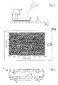
- the test arrangement according to FIG. 1 serves to investigate whether the component surface temperature measured by means of thermography and the surface tension correlate.
- a plate-shaped sample 1 which is moved on a conveyor belt 2 in the direction of the arrow 3, flamed with the flame head 4 with a flame 5.
- the surface temperature is detected with the infrared camera 6.
- the temperature reached during flaming, measured with the infrared camera 6 is changed by changing the speed v of the conveyor belt 2 or change the gas flow rate (burner power) or the distance d of the flame head 4 of the sample 1 and the respective surface energy generated according to the above-mentioned Test ink method determined.
- FIG. 2 shows the dependence of the surface tension on the surface temperature with variation of the speed v of the conveyor belt 2. The measurement results of two evaluation lines are shown.
- the bumper 7 has been coated with a temperature-indicating color coating, specifically the thermal paint SC48 from Kager GmbH, Dietzenbach, Germany.
- the thermal lacquer has a white color at room temperature and turns pink at 48 ° C. If this color change is achieved during flaming, flaming parameters are present which lead to a sufficient surface energy.
- dashed zones 8 are still present in the bumper in which no color change has taken place, so that the flame parameters must be changed accordingly.
- the flame head of the Beflammröboters is in fact rod-shaped and provided with lateral, aligned to the bumper 7 nozzles. This results in particular at more curved zones a greater distance of the flame from the plastic and thus a lower temperature.
Landscapes
- Chemical & Material Sciences (AREA)
- General Chemical & Material Sciences (AREA)
- Health & Medical Sciences (AREA)
- Chemical Kinetics & Catalysis (AREA)
- Medicinal Chemistry (AREA)
- Polymers & Plastics (AREA)
- Organic Chemistry (AREA)
- Application Of Or Painting With Fluid Materials (AREA)
- Investigating Or Analyzing Materials Using Thermal Means (AREA)
- Radiation Pyrometers (AREA)
- Processes Of Treating Macromolecular Substances (AREA)
Applications Claiming Priority (1)
| Application Number | Priority Date | Filing Date | Title |
|---|---|---|---|
| DE200510059095 DE102005059095A1 (de) | 2005-12-10 | 2005-12-10 | Verfahren und Vorrichtung zur Kontrolle der Oberflächenaktivierung eines Kunststoffbauteils |
Publications (3)
| Publication Number | Publication Date |
|---|---|
| EP1795330A2 true EP1795330A2 (fr) | 2007-06-13 |
| EP1795330A3 EP1795330A3 (fr) | 2008-01-02 |
| EP1795330B1 EP1795330B1 (fr) | 2012-01-04 |
Family
ID=37846106
Family Applications (1)
| Application Number | Title | Priority Date | Filing Date |
|---|---|---|---|
| EP06023019A Not-in-force EP1795330B1 (fr) | 2005-12-10 | 2006-11-06 | Procédé et dispositif pour le contrôle de l'activation de surface de pièces en matière plastique |
Country Status (3)
| Country | Link |
|---|---|
| EP (1) | EP1795330B1 (fr) |
| DE (1) | DE102005059095A1 (fr) |
| ES (1) | ES2377028T3 (fr) |
Families Citing this family (2)
| Publication number | Priority date | Publication date | Assignee | Title |
|---|---|---|---|---|
| US20110250547A1 (en) * | 2010-04-12 | 2011-10-13 | Ford Global Technologies, Llc | Burner system and a method of control |
| DE102021002449A1 (de) | 2021-05-07 | 2022-11-10 | Singulus Technologies Aktiengesellschaft | Überwachung einer Beflammungsvorrichtung |
Family Cites Families (8)
| Publication number | Priority date | Publication date | Assignee | Title |
|---|---|---|---|---|
| JPS4885126A (fr) * | 1972-02-14 | 1973-11-12 | ||
| ES487114A0 (es) * | 1978-12-22 | 1980-12-16 | Raychem Sa Nv | Un metodo de circundar un cuerpo |
| US5853510A (en) * | 1994-12-12 | 1998-12-29 | Blue Water Plastics, Inc. | Method for manufacturing a composite |
| DE19508668A1 (de) * | 1995-03-14 | 1996-09-19 | Hoechst Ag | Verfahren zur Behandlung einer siegelfähigen Folienoberfläche |
| US6475316B1 (en) * | 2000-07-07 | 2002-11-05 | 3M Innovative Properties Company | Methods of enhancing adhesion |
| DE20114099U1 (de) * | 2001-08-25 | 2002-01-31 | Giese, Erhard, Dr., 24941 Flensburg | Gasbrennerkopf |
| US6815636B2 (en) * | 2003-04-09 | 2004-11-09 | 3D Systems, Inc. | Sintering using thermal image feedback |
| DE10326217A1 (de) * | 2003-06-11 | 2004-12-30 | Bayerische Motoren Werke Ag | Verfahren zum Erkennen von Fehlern der Haftung einer Beschichtung |
-
2005
- 2005-12-10 DE DE200510059095 patent/DE102005059095A1/de not_active Withdrawn
-
2006
- 2006-11-06 ES ES06023019T patent/ES2377028T3/es active Active
- 2006-11-06 EP EP06023019A patent/EP1795330B1/fr not_active Not-in-force
Also Published As
| Publication number | Publication date |
|---|---|
| EP1795330A3 (fr) | 2008-01-02 |
| ES2377028T3 (es) | 2012-03-21 |
| DE102005059095A1 (de) | 2007-06-14 |
| EP1795330B1 (fr) | 2012-01-04 |
Similar Documents
| Publication | Publication Date | Title |
|---|---|---|
| EP3163293B1 (fr) | Procédé de détection de résidus de surface sur des composants à l'aide du rayonnement uv | |
| EP0599153A1 (fr) | Méthode et appareil pour l'identification de matériaux | |
| EP4372308B1 (fr) | Procédé de contrôle et dispositif de contrôle pour contrôler une couche superficielle | |
| EP3314036B1 (fr) | Procédé de revêtement d'une surface d'une bande métallique ainsi que dispositif de revêtement d'une bande métallique | |
| DE102017205208A1 (de) | Vorrichtung und Verfahren zum Beschichten eines Werkstücks | |
| EP3496935A1 (fr) | Dispositif de fabrication | |
| EP2977157A1 (fr) | Procédé destiné a influencer et a regler un processus de collage | |
| EP1795330A2 (fr) | Procédé et dispositif pour le contrôle de l'activation de surface de pièces en matière plastique | |
| EP3262360A1 (fr) | Dispositif pour des processus contrôlés de ventilation et de durcissement | |
| WO2018206263A1 (fr) | Dispositif et procédé pour l'impression 3d d'une pièce à partir d'un matériau non thermoplastique de type caoutchouc | |
| DE19605520C1 (de) | Verfahren und Vorrichtung zur Charakterisierung lackierter Oberflächen | |
| EP2834039B1 (fr) | Procédé de peinture de pièces automobiles en matière plastique, en particulier de pare-chocs de véhicules automobiles | |
| EP3449207A1 (fr) | Dispositif et procédé pour mesurer un jet de laque pour le revêtement de cartes de circuit imprimé | |
| EP2927003A1 (fr) | Installation de fabrication de plaques en matériau dérivé du bois et procédé de fabrication d'une plaque en matériau dérivé du bois | |
| EP1650544B1 (fr) | Procédé et dispositif de détermination de la mouillabilité d'une surface en mouvement et leur utilisation | |
| WO1997030342A1 (fr) | Procede et dispositif pour la caracterisation de surfaces enduites de peinture | |
| WO2003036269A1 (fr) | Procede et dispositif de determination de la mouillabilite d'une surface et leur utilisation | |
| DE10051169B4 (de) | Handgeführte Bestrahlungseinrichtung und thermisches Bearbeitungsverfahren | |
| DE102015107342B4 (de) | Oberflächenuntersuchung von Bauteilen | |
| DE19754547B4 (de) | Verfahren zur Bestimmung des Deckvermögens einer Lackierung | |
| DE102011053478A1 (de) | Verfahren zur Bestimmung einer Zusammensetzung einer plastifizierten Elastomermischung auf der Basis wenigstens eines polaren oder unpolaren Kautschuks | |
| DE102024114343B4 (de) | System mit einer Beschichtungsvorrichtung und Verfahren zum Aufbringen eines Beschichtungsmediums | |
| DE102022204371B4 (de) | Vorrichtung zur Prüfung des Aushärtungszustandes von KTL beschichteten Bauteilen | |
| DE19909864A1 (de) | Verfahren und Vorrichtung zur Herstellung einer Folienbahn | |
| DE202024002479U1 (de) | Beschichtungsvorrichtung und System zum Aufbringen eines Beschichtungsmediums |
Legal Events
| Date | Code | Title | Description |
|---|---|---|---|
| PUAI | Public reference made under article 153(3) epc to a published international application that has entered the european phase |
Free format text: ORIGINAL CODE: 0009012 |
|
| AK | Designated contracting states |
Kind code of ref document: A2 Designated state(s): AT BE BG CH CY CZ DE DK EE ES FI FR GB GR HU IE IS IT LI LT LU LV MC NL PL PT RO SE SI SK TR |
|
| AX | Request for extension of the european patent |
Extension state: AL BA HR MK YU |
|
| PUAL | Search report despatched |
Free format text: ORIGINAL CODE: 0009013 |
|
| AK | Designated contracting states |
Kind code of ref document: A3 Designated state(s): AT BE BG CH CY CZ DE DK EE ES FI FR GB GR HU IE IS IT LI LT LU LV MC NL PL PT RO SE SI SK TR |
|
| AX | Request for extension of the european patent |
Extension state: AL BA HR MK YU |
|
| 17P | Request for examination filed |
Effective date: 20080129 |
|
| 17Q | First examination report despatched |
Effective date: 20080428 |
|
| AKX | Designation fees paid |
Designated state(s): DE ES FR GB IT |
|
| GRAP | Despatch of communication of intention to grant a patent |
Free format text: ORIGINAL CODE: EPIDOSNIGR1 |
|
| GRAS | Grant fee paid |
Free format text: ORIGINAL CODE: EPIDOSNIGR3 |
|
| GRAA | (expected) grant |
Free format text: ORIGINAL CODE: 0009210 |
|
| AK | Designated contracting states |
Kind code of ref document: B1 Designated state(s): DE ES FR GB IT |
|
| REG | Reference to a national code |
Ref country code: GB Ref legal event code: FG4D Free format text: NOT ENGLISH |
|
| REG | Reference to a national code |
Ref country code: DE Ref legal event code: R096 Ref document number: 502006010788 Country of ref document: DE Effective date: 20120301 |
|
| REG | Reference to a national code |
Ref country code: ES Ref legal event code: FG2A Ref document number: 2377028 Country of ref document: ES Kind code of ref document: T3 Effective date: 20120321 |
|
| PLBE | No opposition filed within time limit |
Free format text: ORIGINAL CODE: 0009261 |
|
| STAA | Information on the status of an ep patent application or granted ep patent |
Free format text: STATUS: NO OPPOSITION FILED WITHIN TIME LIMIT |
|
| 26N | No opposition filed |
Effective date: 20121005 |
|
| REG | Reference to a national code |
Ref country code: DE Ref legal event code: R097 Ref document number: 502006010788 Country of ref document: DE Effective date: 20121005 |
|
| REG | Reference to a national code |
Ref country code: FR Ref legal event code: PLFP Year of fee payment: 10 |
|
| PGFP | Annual fee paid to national office [announced via postgrant information from national office to epo] |
Ref country code: DE Payment date: 20151113 Year of fee payment: 10 |
|
| REG | Reference to a national code |
Ref country code: FR Ref legal event code: PLFP Year of fee payment: 11 |
|
| PGFP | Annual fee paid to national office [announced via postgrant information from national office to epo] |
Ref country code: FR Payment date: 20161124 Year of fee payment: 11 Ref country code: GB Payment date: 20161124 Year of fee payment: 11 |
|
| PGFP | Annual fee paid to national office [announced via postgrant information from national office to epo] |
Ref country code: IT Payment date: 20161124 Year of fee payment: 11 Ref country code: ES Payment date: 20161124 Year of fee payment: 11 |
|
| REG | Reference to a national code |
Ref country code: DE Ref legal event code: R119 Ref document number: 502006010788 Country of ref document: DE |
|
| PG25 | Lapsed in a contracting state [announced via postgrant information from national office to epo] |
Ref country code: DE Free format text: LAPSE BECAUSE OF NON-PAYMENT OF DUE FEES Effective date: 20170601 |
|
| GBPC | Gb: european patent ceased through non-payment of renewal fee |
Effective date: 20171106 |
|
| REG | Reference to a national code |
Ref country code: FR Ref legal event code: ST Effective date: 20180731 |
|
| PG25 | Lapsed in a contracting state [announced via postgrant information from national office to epo] |
Ref country code: FR Free format text: LAPSE BECAUSE OF NON-PAYMENT OF DUE FEES Effective date: 20171130 Ref country code: IT Free format text: LAPSE BECAUSE OF NON-PAYMENT OF DUE FEES Effective date: 20171106 |
|
| PG25 | Lapsed in a contracting state [announced via postgrant information from national office to epo] |
Ref country code: GB Free format text: LAPSE BECAUSE OF NON-PAYMENT OF DUE FEES Effective date: 20171106 |
|
| REG | Reference to a national code |
Ref country code: ES Ref legal event code: FD2A Effective date: 20181226 |
|
| PG25 | Lapsed in a contracting state [announced via postgrant information from national office to epo] |
Ref country code: ES Free format text: LAPSE BECAUSE OF NON-PAYMENT OF DUE FEES Effective date: 20171107 |