EP1795385A2 - Federsitz - Google Patents
Federsitz Download PDFInfo
- Publication number
- EP1795385A2 EP1795385A2 EP06255615A EP06255615A EP1795385A2 EP 1795385 A2 EP1795385 A2 EP 1795385A2 EP 06255615 A EP06255615 A EP 06255615A EP 06255615 A EP06255615 A EP 06255615A EP 1795385 A2 EP1795385 A2 EP 1795385A2
- Authority
- EP
- European Patent Office
- Prior art keywords
- spring
- isolator
- annular ring
- assembly according
- fluid
- Prior art date
- Legal status (The legal status is an assumption and is not a legal conclusion. Google has not performed a legal analysis and makes no representation as to the accuracy of the status listed.)
- Withdrawn
Links
- 239000012530 fluid Substances 0.000 claims abstract description 31
- 230000035939 shock Effects 0.000 claims abstract description 31
- 239000006096 absorbing agent Substances 0.000 claims abstract description 23
- 230000000694 effects Effects 0.000 claims abstract description 7
- 239000011324 bead Substances 0.000 claims description 11
- 238000007789 sealing Methods 0.000 claims description 10
- 230000036961 partial effect Effects 0.000 description 8
- 229920001971 elastomer Polymers 0.000 description 3
- 239000000463 material Substances 0.000 description 2
- 230000002829 reductive effect Effects 0.000 description 2
- 229910000831 Steel Inorganic materials 0.000 description 1
- 230000000712 assembly Effects 0.000 description 1
- 238000000429 assembly Methods 0.000 description 1
- 230000003247 decreasing effect Effects 0.000 description 1
- 239000000806 elastomer Substances 0.000 description 1
- 238000005516 engineering process Methods 0.000 description 1
- 238000009434 installation Methods 0.000 description 1
- 239000002184 metal Substances 0.000 description 1
- 238000012986 modification Methods 0.000 description 1
- 230000004048 modification Effects 0.000 description 1
- 238000009828 non-uniform distribution Methods 0.000 description 1
- 230000002028 premature Effects 0.000 description 1
- 230000002441 reversible effect Effects 0.000 description 1
- 230000003068 static effect Effects 0.000 description 1
- 239000010959 steel Substances 0.000 description 1
Images


Classifications
-
- B—PERFORMING OPERATIONS; TRANSPORTING
- B60—VEHICLES IN GENERAL
- B60G—VEHICLE SUSPENSION ARRANGEMENTS
- B60G11/00—Resilient suspensions characterised by arrangement, location or kind of springs
- B60G11/14—Resilient suspensions characterised by arrangement, location or kind of springs having helical, spiral or coil springs only
- B60G11/15—Coil springs resisting deflection by winding up
-
- F—MECHANICAL ENGINEERING; LIGHTING; HEATING; WEAPONS; BLASTING
- F16—ENGINEERING ELEMENTS AND UNITS; GENERAL MEASURES FOR PRODUCING AND MAINTAINING EFFECTIVE FUNCTIONING OF MACHINES OR INSTALLATIONS; THERMAL INSULATION IN GENERAL
- F16F—SPRINGS; SHOCK-ABSORBERS; MEANS FOR DAMPING VIBRATION
- F16F1/00—Springs
- F16F1/02—Springs made of steel or other material having low internal friction; Wound, torsion, leaf, cup, ring or the like springs, the material of the spring not being relevant
- F16F1/04—Wound springs
- F16F1/12—Attachments or mountings
- F16F1/126—Attachments or mountings comprising an element between the end coil of the spring and the support proper, e.g. an elastomeric annulus
-
- F—MECHANICAL ENGINEERING; LIGHTING; HEATING; WEAPONS; BLASTING
- F16—ENGINEERING ELEMENTS AND UNITS; GENERAL MEASURES FOR PRODUCING AND MAINTAINING EFFECTIVE FUNCTIONING OF MACHINES OR INSTALLATIONS; THERMAL INSULATION IN GENERAL
- F16F—SPRINGS; SHOCK-ABSORBERS; MEANS FOR DAMPING VIBRATION
- F16F13/00—Units comprising springs of the non-fluid type as well as vibration-dampers, shock-absorbers, or fluid springs
- F16F13/002—Units comprising springs of the non-fluid type as well as vibration-dampers, shock-absorbers, or fluid springs comprising at least one fluid spring
-
- B—PERFORMING OPERATIONS; TRANSPORTING
- B60—VEHICLES IN GENERAL
- B60G—VEHICLE SUSPENSION ARRANGEMENTS
- B60G2202/00—Indexing codes relating to the type of spring, damper or actuator
- B60G2202/10—Type of spring
- B60G2202/12—Wound spring
-
- B—PERFORMING OPERATIONS; TRANSPORTING
- B60—VEHICLES IN GENERAL
- B60G—VEHICLE SUSPENSION ARRANGEMENTS
- B60G2202/00—Indexing codes relating to the type of spring, damper or actuator
- B60G2202/30—Spring/Damper and/or actuator Units
- B60G2202/31—Spring/Damper and/or actuator Units with the spring arranged around the damper, e.g. MacPherson strut
- B60G2202/312—The spring being a wound spring
-
- B—PERFORMING OPERATIONS; TRANSPORTING
- B60—VEHICLES IN GENERAL
- B60G—VEHICLE SUSPENSION ARRANGEMENTS
- B60G2204/00—Indexing codes related to suspensions per se or to auxiliary parts
- B60G2204/10—Mounting of suspension elements
- B60G2204/12—Mounting of springs or dampers
- B60G2204/124—Mounting of coil springs
- B60G2204/1242—Mounting of coil springs on a damper, e.g. MacPerson strut
- B60G2204/12422—Mounting of coil springs on a damper, e.g. MacPerson strut anchoring the end coils on the spring support plate
-
- B—PERFORMING OPERATIONS; TRANSPORTING
- B60—VEHICLES IN GENERAL
- B60G—VEHICLE SUSPENSION ARRANGEMENTS
- B60G2204/00—Indexing codes related to suspensions per se or to auxiliary parts
- B60G2204/40—Auxiliary suspension parts; Adjustment of suspensions
- B60G2204/418—Bearings, e.g. ball or roller bearings
-
- F—MECHANICAL ENGINEERING; LIGHTING; HEATING; WEAPONS; BLASTING
- F16—ENGINEERING ELEMENTS AND UNITS; GENERAL MEASURES FOR PRODUCING AND MAINTAINING EFFECTIVE FUNCTIONING OF MACHINES OR INSTALLATIONS; THERMAL INSULATION IN GENERAL
- F16F—SPRINGS; SHOCK-ABSORBERS; MEANS FOR DAMPING VIBRATION
- F16F2224/00—Materials; Material properties
- F16F2224/04—Fluids
- F16F2224/048—High viscosity, semi-solid pastiness
Definitions
- a shock absorber assembly or a spring and isolator assembly includes a fluid isolator positioned between a spring end coil and a spring seat to dynamically compensate for side load forces.
- a typical shock absorber assembly includes a cylinder that slidably receives a piston coupled to a rod. One end of the rod is mounted to the vehicle frame and the cylinder is mounted to a vehicle wheel structure.
- a coil spring reacts between a first spring seat on the cylinder and a second spring seat on the rod.
- coil ends of the coil spring can vary from desired configurations. It is preferred to maintain a center of load, i.e. spring pierce point, to be concentric with the rod. However, the coil ends are typically provided with non-parallel coil end planes, which results in dynamically varying spring pierce points. The interface between the coil ends and associated spring seats can often result in non-uniform distribution of load into the spring seats. This can cause the spring pierce point to move out of a desired location, increasing stress on other shock components.
- One proposed solution utilizes an adjustable spring seat that allows the spring pierce point to be set for a desired shock absorber operational position, prior to installation in a vehicle.
- This adjustable spring seat is disclosed in co-pending application no. 11/327,107, which is assigned to the assignee of the present invention, titled “Static Pierce Point Centering Spring Seat” and filed on even date herewith. While this system has advantages, there is still a need for a system that can dynamically adjust spring pierce point position during vehicle operation to further reduce the effects of side loads.
- a shock absorber assembly or a spring and isolator assembly includes an isolator that distributes non-centered spring end forces through a fluid medium to reduce effects of spring side load forces.
- the isolator comprises an annular ring that includes a fluid cavity, which is positioned between an end coil of a spring and a spring seat.
- an annular ring can be positioned between each end coil of the spring and an associated spring seat.
- the isolator comprises an annular ring with an internal cavity that is completely enclosed within the annular ring.
- an internal pressure is generated within the annular ring. This internal pressure results in an axial force against a properly positioned spring seat to reduce spring side load forces.
- a spring pierce point is maintained near a center of the spring, which is desirable.
- the spring pierce point comprises a center of load at the spring seat. Reaction members can optionally be placed between the end coils and annular ring to more evenly transfer loading to the annular ring.
- the isolator comprises an annular ring that cooperates with a spring seat to define an internal cavity.
- a sealing bead similar to sealing bead formed on a tire for engagement with a rim, is formed about the annular ring.
- the sealing bead engages the spring seat to provide a sealed fluid cavity that is filled with fluid.
- a non-uniform force pattern generated by the end coils due to side load forces is transferred into the fluid, and is evenly distributed out to the associated spring seat. This allows the spring seat to tilt and neutralize natural spring loads and off-center pierce points, i.e. off-centering loading at the spring seat.
- the subject invention provides a shock absorber assembly that utilizes a fluid filled isolator to dynamically adjust relative loading positions between spring end coils and associated spring seats.
- the fluid filled isolator functions to maintain a spring pierce point generally concentric with a shock rod to reduce the effects of side loading during vehicle operation. This reduces stress on other components of the shock absorber assembly.
- Figure 1 shows a shock absorber 10 including a cylinder 12 with a first mount 14, a piston 16 received within the cylinder 12, and a rod 18 coupled to the piston 16.
- the rod 18 defines an axis A that extends along a length of the rod 18. The rod 18 moves the piston 16 back and forth within the cylinder 12 along the axis A to compensate for road load inputs as known.
- a second mount 20 is attached to the rod 18.
- the second mount 20 is attached to a vehicle structure 22, such as a frame or chassis member for example.
- the first mount 14 is attached to a wheel structure 24, such as control arm for example.
- a reverse orientation could also be used with the first mount 14 being attached to the vehicle structure 22 and the second mount 20 being attached to the wheel structure 24.
- the first 14 and second 20 mounts can be pivoting mounts as shown in Figure 1, or could be a fixed mount such as that shown in Figure 2A.
- a first support or spring seat 30 is fixed to the cylinder 12 as shown in Figure 1.
- a second support or spring seat 32 is fixed to the rod 18.
- the first spring seat 30 is preferably mounted directly to an exterior surface of the cylinder 12.
- the second spring seat 32 is preferably fixed to a portion of the rod 18 that extends outwardly of the cylinder 12, and which is positioned near the second mount 20.
- a spring 34 reacts between the first 30 and second 32 spring seats.
- the spring 34 has a first coil end 36 that is associated with the first spring seat 30 and a second coil end 38 that is associated with the second spring seat 32.
- An isolator 40 is positioned between each of the first 36 and second 38 coil ends and a respective one of the first 30 and second 32 spring seats.
- a single isolator 40 may be positioned at either of the first 30 and second 32 spring seats.
- the isolator 40 provides a sealed fluid cavity that is filled with any suitable fluid, such as hydraulic fluid for example.
- any suitable fluid such as hydraulic fluid for example.
- the isolator 40 is shown in a shock absorber 10, the subject invention could also be utilized as a clip-on component to make a spring/isolator assembly.
- the isolators 40 serve as a mechanism for evenly distributing non-centered spring forces, such as spring side loads for example, throughout a fluid medium resulting in generation of an internal pressure within the isolator 40.
- the internal pressure within the isolator 40 results in an axial force being applied against an associated spring seat (see figure 2A), which significantly reduces side load forces.
- the isolator 40 is installed between the second spring seat 32 and the second coil end 38.
- a similar isolator would be positioned between the first spring seat 30 and first coil end 36 if needed.
- the isolator 40 comprises an annular ring 42 with an internal cavity 44 that is completely enclosed within the annular ring 42. Fluid at least partially fills the internal cavity 44.
- the annular ring 42 can resiliently respond to non-centered spring forces by compressing or expanding sections of the annular ring 42.
- the isolator 40 allows the second spring seat 32 and second coil end 38 to move relative to each other to compensate for these non-centered spring forces. This allows the center of load or "spring pierce point" 48 ( Figure 2B) at the first spring seat 30 to be continuously adjusted.
- the resiliency of the isolator 40 allows the spring pierce point 48 to be actively maintained in a generally concentric relationship with the rod 18, i.e. the isolator 40 generally positions the spring pierce point 48 along the axis A. This reduces the effects of side loading forces.
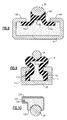
- an isolator 50 comprises an annular ring similar to that of Figure 2A, and has a generally toroidal shape when not subjected to a load (Figure 3A).
- Figure 3B When the isolator 50 is subjected to a load ( Figure 3B), the isolator 50 assumes a generally rectangular cross-sectional shape. Any angular motion as allowed by various component clearances within the shock absorber 10, would result in an internal pressure within the isolator 50. This would exert a vertical load against the isolator 50 as shown by the arrow in Figure 3B.
- a reaction member such as a washer 52 or stamped ring, could be used to more evenly transfer loading from the second coil end 38 to the isolator 50.
- an isolator 60 comprises an annular ring similar to those described above, but includes a spring interface 62 that is integrally formed with the isolator 60.
- the spring interface 62 preferably comprises a groove that is formed in a lower surface 64 of the isolator 60.
- an isolator 70 comprises an annular ring similar to those described above, but includes a locating or piloting ring 72.
- the piloting ring 72 is preferably a stamped metal ring that extends transversely relative to the isolator 70 and surrounds at least a portion of an outer circumference of the second coil end 38.
- the example shown in Figure 6 discloses an isolator 80 that uses features from the examples of Figure 3B and Figure 5.
- the isolator 80 uses a reaction member 82 that includes a first portion 84 that is similar to the washer 52 of Figure 3B, and which is used to evenly distribute loads to the isolator 80.
- the reaction member 82 also includes a second portion 86 that is similar to the piloting ring 72 of Figure 5.
- the second portion 86 extends transversely to the first portion 84, and can be integrally formed with or separately formed from the first portion 84.
- Figures 7-10 disclose another type of fluid isolator.
- a sealed fluid cavity is formed between one of the spring seats and the fluid isolator.
- an isolator 90 comprises an annular ring with an upper surface 92 that defines a portion of a sealed cavity 94.
- At least one sealing bead 96 is circumferentially formed about the annular ring to engage the second spring seat 32.
- the sealing bead 96 is similar to a tire bead that is formed on a vehicle tire for engagement with a wheel rim.
- the sealing bead 96 is compressed under pressure against inner walls of the second spring seat 32 to form the sealed cavity 94.
- This isolator 90 performs similarly to those described above, and allows the relative movement, i.e. tilting movement for example, between the second coil end 38 and second spring seat 32. This tilting movement neutralizes natural spring loads and off-center spring pierce points.
- an isolator 100 includes horizontally extending flanges 102 with sealing beads that engage inwardly extending walls 104 of the second spring seat 32.
- the isolator 100 includes an integrally formed spring interface 106 as shown.
- an isolator 110 includes vertically extending flanges 112 with sealing beads that engage vertical walls 114 of the second spring seat 32.
- the isolator 110 includes an integrally formed spring interface 116 as shown.
- an isolator 120 cooperates with a roll crimped edge 122 of a spring seat 124. This provides integral attachment of the isolator 120 to the spring seat 124 with the crimped edge 122 being formed around a beaded section 126 to offer a hydraulic type seal.
- a smaller shock absorber can be utilized to offset any cost associated with the inclusion of the isolator.
- the size of the rod 18 could be reduced, the wall thickness of the cylinder could be decreased, and/or lower capacity bearings/seals could be realized. Any of these would provide reduced costs and weight of the assembly. Further, lower side loads also reduce friction between the rod and associated bearings/seals, resulting in an improved vehicle ride.
- the spring seats are preferably formed from a steel material and the isolator is preferably formed from an elastomer material, such as rubber for example.
- internal fluid pressures are moderately low, i.e. in the general range of 2000-3000 psi. This pressure range corresponds to existing hydraulic pressures through traditional rubber hose technology.
Landscapes
- Engineering & Computer Science (AREA)
- General Engineering & Computer Science (AREA)
- Mechanical Engineering (AREA)
- Fluid-Damping Devices (AREA)
- Springs (AREA)
- Vehicle Body Suspensions (AREA)
Applications Claiming Priority (1)
| Application Number | Priority Date | Filing Date | Title |
|---|---|---|---|
| US11/299,569 US7624973B2 (en) | 2005-12-12 | 2005-12-12 | Dynamic pierce point centering spring seat |
Publications (2)
| Publication Number | Publication Date |
|---|---|
| EP1795385A2 true EP1795385A2 (de) | 2007-06-13 |
| EP1795385A3 EP1795385A3 (de) | 2007-11-14 |
Family
ID=37859596
Family Applications (1)
| Application Number | Title | Priority Date | Filing Date |
|---|---|---|---|
| EP06255615A Withdrawn EP1795385A3 (de) | 2005-12-12 | 2006-11-01 | Federsitz |
Country Status (4)
| Country | Link |
|---|---|
| US (1) | US7624973B2 (de) |
| EP (1) | EP1795385A3 (de) |
| JP (1) | JP2007162941A (de) |
| BR (1) | BRPI0605277A (de) |
Cited By (4)
| Publication number | Priority date | Publication date | Assignee | Title |
|---|---|---|---|---|
| CN105522880A (zh) * | 2014-10-21 | 2016-04-27 | 福特全球技术公司 | 用于车辆车轮悬架的弹簧隔振器和车辆车轮悬架 |
| FR3057322A1 (fr) * | 2016-10-06 | 2018-04-13 | Peugeot Citroen Automobiles Sa | Double volant moteur comportant des amortisseurs hydrauliques |
| CN108163481A (zh) * | 2017-12-30 | 2018-06-15 | 芜湖哈特机器人产业技术研究院有限公司 | 一种减震式自动导引运输车 |
| WO2020043889A1 (de) * | 2018-08-31 | 2020-03-05 | ThyssenKrupp Federn und Stabilisatoren GmbH | Feder-federteller-anordnung für ein fahrwerk und ein verfahren zum herstellen einer feder-federteller-anordnung für ein fahrzeugfahrwerk |
Families Citing this family (4)
| Publication number | Priority date | Publication date | Assignee | Title |
|---|---|---|---|---|
| US7357382B2 (en) * | 2001-07-25 | 2008-04-15 | Matthew Warren, Inc. | Hydraulic load centering spring perch |
| US9494210B2 (en) * | 2006-08-04 | 2016-11-15 | Honda Motor Co., Ltd. | Vehicle mount and method |
| DE102015200181A1 (de) | 2015-01-09 | 2016-07-14 | Ford Global Technologies, Llc | Federunterlage für eine Fahrzeugradaufhängung und Fahrzeugradaufhängung |
| US10471793B2 (en) * | 2016-10-12 | 2019-11-12 | Ford Global Technologies, Llc | Seat mounts for side load spring on a twist beam axle |
Family Cites Families (14)
| Publication number | Priority date | Publication date | Assignee | Title |
|---|---|---|---|---|
| US4094280A (en) * | 1976-07-06 | 1978-06-13 | Trw Inc. | Valve rotating device |
| US4562997A (en) * | 1982-04-14 | 1986-01-07 | Nissan Motor Company, Limited | Shock absorber assembly for automotive vehicle suspension |
| US4738434A (en) | 1986-04-07 | 1988-04-19 | Marjoram Robert H | Vibration and/or shock attenuating fluid mount or the like |
| JPS62251219A (ja) * | 1986-04-23 | 1987-11-02 | Mazda Motor Corp | 自動車のサスペンシヨン装置 |
| US4720087A (en) | 1986-09-05 | 1988-01-19 | Lord Corporation | Inertia type fluid mount using electrorheological and other fluid |
| US4830395A (en) * | 1988-02-22 | 1989-05-16 | Foley Jimmy D | Stabilizer system for racing cars |
| US5246215A (en) * | 1989-06-16 | 1993-09-21 | Nhk Spring Co., Ltd. | Spring seat member with notch for ground spring end |
| US5984283A (en) * | 1996-03-29 | 1999-11-16 | Toyoda Gosei Co., Ltd. | Vibration-damping rubber in suspension of vehicle |
| DE19632805C2 (de) * | 1996-08-16 | 1999-02-04 | Daimler Benz Ag | Vorrichtung zur höhenveränderlichen Abstützung einer Rad- oder Achsfederung am Aufbau eines Kraftfahrzeugs |
| US6378851B1 (en) | 2000-10-25 | 2002-04-30 | Lord Corporation | Fluid and elastomer apparatus with discrete volume compensator and secondary compliance |
| US6705438B2 (en) | 2001-07-11 | 2004-03-16 | Delphi Technologies, Inc. | Method for attaching ring to damper base cup and damper having ring |
| US20030020221A1 (en) * | 2001-07-25 | 2003-01-30 | Richard Pare | Load centering spring perch |
| JP4099996B2 (ja) | 2002-01-22 | 2008-06-11 | オイレス工業株式会社 | スラスト滑り軸受 |
| JP4055845B2 (ja) * | 2002-05-08 | 2008-03-05 | 株式会社ショーワ | 油圧緩衝器のダストカバー受け構造 |
-
2005
- 2005-12-12 US US11/299,569 patent/US7624973B2/en not_active Expired - Fee Related
-
2006
- 2006-11-01 EP EP06255615A patent/EP1795385A3/de not_active Withdrawn
- 2006-12-06 JP JP2006329170A patent/JP2007162941A/ja active Pending
- 2006-12-11 BR BRPI0605277-0A patent/BRPI0605277A/pt not_active Application Discontinuation
Cited By (6)
| Publication number | Priority date | Publication date | Assignee | Title |
|---|---|---|---|---|
| CN105522880A (zh) * | 2014-10-21 | 2016-04-27 | 福特全球技术公司 | 用于车辆车轮悬架的弹簧隔振器和车辆车轮悬架 |
| CN105522880B (zh) * | 2014-10-21 | 2020-01-14 | 福特全球技术公司 | 用于车辆车轮悬架的弹簧隔振器和车辆车轮悬架 |
| FR3057322A1 (fr) * | 2016-10-06 | 2018-04-13 | Peugeot Citroen Automobiles Sa | Double volant moteur comportant des amortisseurs hydrauliques |
| CN108163481A (zh) * | 2017-12-30 | 2018-06-15 | 芜湖哈特机器人产业技术研究院有限公司 | 一种减震式自动导引运输车 |
| CN108163481B (zh) * | 2017-12-30 | 2019-11-19 | 芜湖哈特机器人产业技术研究院有限公司 | 一种减震式自动导引运输车 |
| WO2020043889A1 (de) * | 2018-08-31 | 2020-03-05 | ThyssenKrupp Federn und Stabilisatoren GmbH | Feder-federteller-anordnung für ein fahrwerk und ein verfahren zum herstellen einer feder-federteller-anordnung für ein fahrzeugfahrwerk |
Also Published As
| Publication number | Publication date |
|---|---|
| BRPI0605277A (pt) | 2007-10-09 |
| EP1795385A3 (de) | 2007-11-14 |
| US7624973B2 (en) | 2009-12-01 |
| US20070131501A1 (en) | 2007-06-14 |
| JP2007162941A (ja) | 2007-06-28 |
Similar Documents
| Publication | Publication Date | Title |
|---|---|---|
| US5797594A (en) | Hydraulic shock absorber | |
| US4828232A (en) | Vehicle air suspension strut with compliant cover plate assembly | |
| EP4010210B1 (de) | Montageanordnungen sowie gasfeder- und dämpferanordnungen und aufhängungssysteme damit | |
| US4648623A (en) | Vehicle suspension strut with lower rotary bearing cup assembly for a dirigible road wheel | |
| US20130234377A1 (en) | Gas spring and gas damper assembly and method | |
| EP0825357B1 (de) | Einzelrohrdämpfer | |
| US7624973B2 (en) | Dynamic pierce point centering spring seat | |
| US9695901B2 (en) | Gas spring system | |
| CN110831793B (zh) | 具有密封的封闭盖的空气弹簧滑柱 | |
| US9296272B2 (en) | Gas spring and gas damper assembly and method | |
| US20230041250A1 (en) | Gas spring and damper assemblies as well as suspension systems including same | |
| EP0257779B1 (de) | Luftfeder und Dämpfer für Fahrzeugaufhängung | |
| US7108253B2 (en) | Mounting assembly | |
| US20040017030A1 (en) | Pneumatic spring assembly | |
| EP1255057B1 (de) | Schwingungsdämpfer mit einer schwimmenden Kolbenstangenführung | |
| US6814346B2 (en) | Shock absorber | |
| US7077052B2 (en) | Strut assembly with inverted air spring configuration | |
| US20070158925A1 (en) | Static pierce point centering spring seat | |
| US20060208403A1 (en) | Air spring assembly with flexible can | |
| JP2004017769A (ja) | 懸架装置 | |
| CN119062707B (zh) | 机械式双腔空气弹簧 | |
| US20040169323A1 (en) | MacPherson strut spring coil mounts | |
| US20240157745A1 (en) | Support System With Air Reservoir | |
| CN224145705U (zh) | 空气弹簧总成及车辆 | |
| JPS5841398Y2 (ja) | カ−トリツジシヨツクアブソ−バ |
Legal Events
| Date | Code | Title | Description |
|---|---|---|---|
| PUAI | Public reference made under article 153(3) epc to a published international application that has entered the european phase |
Free format text: ORIGINAL CODE: 0009012 |
|
| AK | Designated contracting states |
Kind code of ref document: A2 Designated state(s): AT BE BG CH CY CZ DE DK EE ES FI FR GB GR HU IE IS IT LI LT LU LV MC NL PL PT RO SE SI SK TR |
|
| AX | Request for extension of the european patent |
Extension state: AL BA HR MK YU |
|
| PUAL | Search report despatched |
Free format text: ORIGINAL CODE: 0009013 |
|
| AK | Designated contracting states |
Kind code of ref document: A3 Designated state(s): AT BE BG CH CY CZ DE DK EE ES FI FR GB GR HU IE IS IT LI LT LU LV MC NL PL PT RO SE SI SK TR |
|
| AX | Request for extension of the european patent |
Extension state: AL BA HR MK YU |
|
| 17P | Request for examination filed |
Effective date: 20080317 |
|
| 17Q | First examination report despatched |
Effective date: 20080425 |
|
| AKX | Designation fees paid |
Designated state(s): AT BE BG CH CY CZ DE DK EE ES FI FR GB GR HU IE IS IT LI LT LU LV MC NL PL PT RO SE SI SK TR |
|
| STAA | Information on the status of an ep patent application or granted ep patent |
Free format text: STATUS: THE APPLICATION IS DEEMED TO BE WITHDRAWN |
|
| 18D | Application deemed to be withdrawn |
Effective date: 20100317 |