EP1795471A2 - Cylindre conducteur ou contacteur pour la manipulation d'un materiau en bande - Google Patents
Cylindre conducteur ou contacteur pour la manipulation d'un materiau en bande Download PDFInfo
- Publication number
- EP1795471A2 EP1795471A2 EP06123716A EP06123716A EP1795471A2 EP 1795471 A2 EP1795471 A2 EP 1795471A2 EP 06123716 A EP06123716 A EP 06123716A EP 06123716 A EP06123716 A EP 06123716A EP 1795471 A2 EP1795471 A2 EP 1795471A2
- Authority
- EP
- European Patent Office
- Prior art keywords
- guide
- winding
- contact roller
- material web
- temperature sensor
- Prior art date
- Legal status (The legal status is an assumption and is not a legal conclusion. Google has not performed a legal analysis and makes no representation as to the accuracy of the status listed.)
- Granted
Links
Images
Classifications
-
- B—PERFORMING OPERATIONS; TRANSPORTING
- B65—CONVEYING; PACKING; STORING; HANDLING THIN OR FILAMENTARY MATERIAL
- B65H—HANDLING THIN OR FILAMENTARY MATERIAL, e.g. SHEETS, WEBS, CABLES
- B65H26/00—Warning or safety devices, e.g. automatic fault detectors, stop-motions, for web-advancing mechanisms
- B65H26/02—Warning or safety devices, e.g. automatic fault detectors, stop-motions, for web-advancing mechanisms responsive to presence of irregularities in running webs
- B65H26/025—Warning or safety devices, e.g. automatic fault detectors, stop-motions, for web-advancing mechanisms responsive to presence of irregularities in running webs responsive to web breakage
-
- B—PERFORMING OPERATIONS; TRANSPORTING
- B65—CONVEYING; PACKING; STORING; HANDLING THIN OR FILAMENTARY MATERIAL
- B65H—HANDLING THIN OR FILAMENTARY MATERIAL, e.g. SHEETS, WEBS, CABLES
- B65H18/00—Winding webs
- B65H18/02—Supporting web roll
- B65H18/028—Both ends type
-
- B—PERFORMING OPERATIONS; TRANSPORTING
- B65—CONVEYING; PACKING; STORING; HANDLING THIN OR FILAMENTARY MATERIAL
- B65H—HANDLING THIN OR FILAMENTARY MATERIAL, e.g. SHEETS, WEBS, CABLES
- B65H18/00—Winding webs
- B65H18/08—Web-winding mechanisms
- B65H18/14—Mechanisms in which power is applied to web roll, e.g. to effect continuous advancement of web
- B65H18/16—Mechanisms in which power is applied to web roll, e.g. to effect continuous advancement of web by friction roller
-
- B—PERFORMING OPERATIONS; TRANSPORTING
- B65—CONVEYING; PACKING; STORING; HANDLING THIN OR FILAMENTARY MATERIAL
- B65H—HANDLING THIN OR FILAMENTARY MATERIAL, e.g. SHEETS, WEBS, CABLES
- B65H23/00—Registering, tensioning, smoothing or guiding webs
- B65H23/04—Registering, tensioning, smoothing or guiding webs longitudinally
- B65H23/18—Registering, tensioning, smoothing or guiding webs longitudinally by controlling or regulating the web-advancing mechanism, e.g. mechanism acting on the running web
- B65H23/182—Registering, tensioning, smoothing or guiding webs longitudinally by controlling or regulating the web-advancing mechanism, e.g. mechanism acting on the running web in unwinding mechanisms or in connection with unwinding operations
-
- B—PERFORMING OPERATIONS; TRANSPORTING
- B65—CONVEYING; PACKING; STORING; HANDLING THIN OR FILAMENTARY MATERIAL
- B65H—HANDLING THIN OR FILAMENTARY MATERIAL, e.g. SHEETS, WEBS, CABLES
- B65H2301/00—Handling processes for sheets or webs
- B65H2301/40—Type of handling process
- B65H2301/41—Winding, unwinding
- B65H2301/414—Winding
- B65H2301/4148—Winding slitting
- B65H2301/41486—Winding slitting winding on two or more winding shafts simultaneously
- B65H2301/414863—Winding slitting winding on two or more winding shafts simultaneously directly against central support roller
Definitions
- the invention relates to a guide or contact roller arrangement for handling a material web, in particular in a winding machine whose peripheral surface at least partially forms a portion of a path of the material web from a first position to a second position, wherein at least one material web sensor is provided on the guide or contact roller ,
- the invention relates to a winding machine for winding a material web, in particular a paper or board web, on a winding tube to at least one winding roll, which forms a winding nip with at least one axially parallel and adjacent contact roller.
- a paper web is today produced virtually "endlessly" on paper machines whose working width is greater than that of the users, for example printers, desired width. For this reason, the paper webs must be cut in one of the last manufacturing steps to the appropriate width and then rolled up or wound up. This always results in at least two, but usually even more cut bobbins. To wind these bobbins two different ways are known.
- all bobbins can be wound axially next to each other in a common winding bed, which is formed by two or more support rollers. This winding thus takes place after the support roller principle.
- a problem with winding such cut paper webs into winding rolls is that a single paper web can occasionally tear. Such cracks are not or only poorly predictable. In certain areas of the path of the paper web can be seen a demolition by measuring the tension there accordingly. From the time when the cut paper web runs onto the contact roller, however, such a tensile stress measurement is relatively difficult with reasonable effort and without damaging the cut paper web. However, the problem of a web break also occurs there, that is directly on the contact roller. If the torn paper web is further transported to the winding, that is, to the winding positions, but is not wound there, there is a considerable Risk of destruction of components on the winding machine. Such a component can be, for example, the contact roller whose coating can be damaged to such an extent that even a roller replacement is necessary. In addition, the subsequent "tidying up" is relatively tedious and time consuming.
- the material web sensor is preferably designed as a non-contact, in particular optical sensor, which does not stress the material web and also leaves no markings that could disturb the subsequent further processing of the material web.
- a material web sensor has the serious disadvantage that it responds as far as possible to environmental influences. Since the machine, in which such a material web sensor is installed, is usually not characterized by purity and cleanliness, it can lead to contamination and deposits on the material web sensor over time. These contaminants and deposits, in turn, can impair its functioning in a lasting manner, as a rule permanently impairing it. So it may well happen that the control of the machine due to a false signal generated by the material web sensor, the machine via an emergency stop even brings to a standstill. This ultimately provides a not negligible loss of production and also requires a restoration of the operability of the web sensor, for example, by consuming cleaning and readjustment.
- the invention has for its object to determine a simple and reliable way to demolish a web.
- the material web sensor comprises a temperature sensor which is arranged on a stationary, the guide or contact roller adjacent component and which is aligned with the guide or contact roller.
- the reliable and in its construction extremely robust temperature sensor determines in a simple and also safe way, whether or not the web of material guided during the operation of the machine in a certain way past the guide or contact roller.
- the operation is undisturbed, that is, the web is not cracked, then you can determine this. In this case, namely, the web is properly, that is flat on the guide or contact roller and the temperature sensor recorded no increase in temperature.
- the temperature sensor preferably generates a signal that is preferably continuously amplified during rotation of the guide roller or contact roller, at least in the event of a fault. For this signal, which preferably amplifies continuously in the event of a fault, it is then possible to set control-relevant limit values, above which certain measures are taken.
- the temperature sensor exclusively generates a signal which preferably continuously amplifies during rotation of the guide roller or contact roller in the event of a fault.
- the monitoring effort and monitoring complexity can be minimized.
- the temperature sensor is preferably provided within the section of the path of travel of the material web from the first position to the second position.
- At least two temperature sensors can be provided, in which case at least one temperature sensor within the section of the path of the material web from the first position to the second position and at least one further Temperature sensor outside the section of the is provided.
- the stationary and the guide or contact roller adjacent component is under practical and constructive aspects preferably a bearing part for the guide or contact roller, in particular a reel stand or a guide head exhibiting support arm.
- a bearing part for the guide or contact roller in particular a reel stand or a guide head exhibiting support arm.
- one of the two types of components is available from the start, so that the installation of the temperature sensor is optimally executed with regard to its mechanics and its energy supply.
- a winding machine for winding a material web, in particular a paper or board web, on a winding tube to at least one winding roll, which forms a winding nip with at least one axially parallel and adjacent contact roller, has at least one described temperature sensor.
- the winding machine can have a contact roller designed as a support roller, against which the winding rollers mounted by means of reeling beams rest axially offset from one another at different circumferential positions in at least two winding position groups.
- at least one temperature sensor can be provided in each case at several, preferably at all Aufrollböcken. This winding thus takes place after the back-up roll principle.
- the winding machine can have two contact rollers designed as support rollers, which form a winding bed for the at least one wound reel preferably mounted on the end side by means of support arms.
- at least one temperature sensor can be provided in each case on at least one support arm, preferably two support arms. This winding thus takes place after the support roller principle.
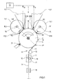
- the single figure shows a schematic and partial view of a winding machine 1 for winding a cut material web 2, in particular a paper or board web.
- the winding machine 1 is designed as a back-up roll winder and comprises a contact roll 3 designed as a support roll 4, against which a plurality of winding rolls 5.1, 5.2 mounted by means of take-up blocks 6.1, 6.2 abut each other at different circumferential positions B1, B2 in at least two winding position groups A1, A2. While the cut material webs 2, which are wound in the circumferential position B1, loop around the support roller 4 by about 90 °, the cut material webs 2, which are wound in the circumferential position B2, guided over the support roller 4 over about 180 °.
- the winding machine 1 is in the direction of L (arrow) of the webs 2 upstream of a roller cutting device 7.
- the entire area in front of the support roller 4 is referred to as Zuurerabites 8 for simplicity.
- a usually machine-width material web 9, for example, a paper or board web unwound from a jumbo or mother roll, is supplied.
- the web 8 passes through a cutting section 10, in which it is divided by a known per se, such as cutting blade 11, 12, in several webs 2.
- the cutting blades 11, 12 cut the material web 9, which is subsequently guided over a further roller 13, in this case in its longitudinal direction.
- a certain tensile force is required, which is applied via the support roller 4, which is also referred to as the central roller.
- the winding rollers 5.1, 5.2 formed on the winding tubes 14 are so strongly pressed against the surface of the support roller 4 when a respective nip N1, N2 (winding nip) is formed, that the resulting frictional engagement is sufficient to cut the material web 9 in material webs 2 to transfer necessary traction.
- a web tension measuring device 15 is shown schematically, which determines the tension of the material web 9 in front of the roller cutting device 7. If this voltage suddenly decreases, this indicates a web break and the winding machine 1 and especially the material web feed can be stopped.
- At least one material web sensor 17, which comprises a temperature sensor 18, is provided in the region of the travel path 16 of the respective web 2 from a first position P1 to a second position P21 or P22.
- the temperature sensor 18 is arranged on the stationary, the backup roller 4 adjacent retractor 6.1 and 6.2 and aligned with the support roller 4. It is thus provided within the section of the running path 16 of the respective material web 2 from the first position P1 to the second position P21 or P22.
- at least one temperature sensor 18 is preferably provided on a plurality of, preferably on all Aufrollböcken 6.1 and 6.2 respectively.
- the temperature sensor 18 generates a signal 19 (arrow) which preferably continuously amplifies during rotation of the support roller 4, at least in the event of a fault, which signal is passed on to a control unit 20 assigned to the winding machine 1 and indicated only if necessary.
- the generated signal 19 (arrow) can then trigger an emergency stop for the winding machine 1, for example via the controller 20, in order to protect it from further and possibly even greater damage in the event of a fault.
- the temperature sensor 19 exclusively generates a signal 19 (arrow) that preferably continuously amplifies during rotation of the support roller 4 in the event of a fault.
- At least two temperature sensors 18, 21 may be provided, wherein at least one temperature sensor 19 within the portion of the running path 16 of the material web 2 from the first position P1 to the second position P21 or P22 and at least one further temperature sensor 21 is provided outside the portion of the running path 16 of the web 2 from the first position P1 to the second position P21 and P22, respectively.
- the at least one further temperature sensor 21 is indicated only schematically, with its structure and function with those of the at least one temperature sensor 19 largely coincide.
- the winding machine 1 shown in the figure may also have two contact rollers designed as support rollers which form a winding bed for the at least one winding roller mounted on the end side by means of support arms.
- at least one temperature sensor 18 can be provided in each case on at least one support arm, preferably both support arms.
- both a guide or contact roller assembly for handling a web and a winding machine for winding a web of the aforementioned types are developed such that in a simple and reliable way, a demolition of a web can be determined.
Landscapes
- Replacement Of Web Rolls (AREA)
- Controlling Rewinding, Feeding, Winding, Or Abnormalities Of Webs (AREA)
- Registering, Tensioning, Guiding Webs, And Rollers Therefor (AREA)
Applications Claiming Priority (1)
| Application Number | Priority Date | Filing Date | Title |
|---|---|---|---|
| DE102005000180A DE102005000180A1 (de) | 2005-12-12 | 2005-12-12 | Leit- oder Kontaktwalzenanordnung zum Handhaben einer Materialbahn |
Publications (3)
| Publication Number | Publication Date |
|---|---|
| EP1795471A2 true EP1795471A2 (fr) | 2007-06-13 |
| EP1795471A3 EP1795471A3 (fr) | 2009-01-14 |
| EP1795471B1 EP1795471B1 (fr) | 2010-04-14 |
Family
ID=37847057
Family Applications (1)
| Application Number | Title | Priority Date | Filing Date |
|---|---|---|---|
| EP06123716A Not-in-force EP1795471B1 (fr) | 2005-12-12 | 2006-11-09 | Cylindre conducteur ou contacteur pour la manipulation d'un materiau en bande |
Country Status (3)
| Country | Link |
|---|---|
| EP (1) | EP1795471B1 (fr) |
| AT (1) | ATE464261T1 (fr) |
| DE (2) | DE102005000180A1 (fr) |
Cited By (1)
| Publication number | Priority date | Publication date | Assignee | Title |
|---|---|---|---|---|
| DE102007025804A1 (de) * | 2007-06-02 | 2008-12-04 | Voith Patent Gmbh | Wickelvorrichtung |
Family Cites Families (1)
| Publication number | Priority date | Publication date | Assignee | Title |
|---|---|---|---|---|
| DE19944958C2 (de) * | 1999-09-20 | 2002-02-07 | Voith Paper Patent Gmbh | Leit- oder Kontaktwalzenanordnung zum Handhaben einer Materialbahn, insbesondere in einer Rollenwickelvorrichtung |
-
2005
- 2005-12-12 DE DE102005000180A patent/DE102005000180A1/de not_active Withdrawn
-
2006
- 2006-11-09 AT AT06123716T patent/ATE464261T1/de active
- 2006-11-09 DE DE502006006687T patent/DE502006006687D1/de active Active
- 2006-11-09 EP EP06123716A patent/EP1795471B1/fr not_active Not-in-force
Cited By (1)
| Publication number | Priority date | Publication date | Assignee | Title |
|---|---|---|---|---|
| DE102007025804A1 (de) * | 2007-06-02 | 2008-12-04 | Voith Patent Gmbh | Wickelvorrichtung |
Also Published As
| Publication number | Publication date |
|---|---|
| ATE464261T1 (de) | 2010-04-15 |
| DE502006006687D1 (de) | 2010-05-27 |
| EP1795471B1 (fr) | 2010-04-14 |
| DE102005000180A1 (de) | 2007-06-14 |
| EP1795471A3 (fr) | 2009-01-14 |
Similar Documents
| Publication | Publication Date | Title |
|---|---|---|
| DE3639244C2 (de) | Tragwalzenwickelapparat für bewegte Bahnen | |
| DE69627889T2 (de) | System für einen geldautomaten zur erfassung eines fehlers bei der zufuhr vonpapier eines journaldruckers | |
| DE69806269T2 (de) | Verfahren und vorrichtung in einer papiermaschine, einer beschichtungsmaschine, einer umrollmaschine, einer abwickelstation in einem längsschneide-wickler oder in einer anderen vorrichtung zum verarbeiten einer bahn | |
| DE2935743A1 (de) | Zusatzvorrichtung an aufrolleinrichtungen und verfahren zum aufrollen von druckempfindlichen materialbahnen | |
| DE19882374B4 (de) | Verfahren zur Bestimmung der Qualität der Formierung einer Bobine oder Rolle einer Papier - oder Kartonbahn und zur Steuerung der Bobinen - oder Rollenformierung und - wicklung | |
| EP3934997B1 (fr) | Entraînement de machines de découpe de bobines | |
| EP0887293B1 (fr) | Dispositif de coupe à rouleaux pour une bande de matière | |
| EP1795471B1 (fr) | Cylindre conducteur ou contacteur pour la manipulation d'un materiau en bande | |
| DE10036306B4 (de) | Verfahren und Vorrichtung zum gleichzeitigen Wickeln von mehreren Teilbahnen zu Teilbahnrollen | |
| DE69708979T2 (de) | Verfahren und Vorrichtung zum Aufwickeln einer Papierbahn | |
| DE60110842T2 (de) | Verfahren und vorrichtung zum aufwickeln einer papier- oder kartonbahn | |
| EP1513756B1 (fr) | Dispositif de detection d'une perturbation dans le defilement d'une bande | |
| DE10312384B3 (de) | Verfahren zum Überwachen einer laufenden Bahn auf einem Abriss und Durchführung des Verfahrens geeignete Vorrichtung | |
| EP1084976A2 (fr) | Cylindre conducteur ou contacteur pour la manipulation de matériau en bande, en particulier dans un dispositif d'enroulement de bande | |
| DE10244218A1 (de) | Vorrichtung zur Reinigung eines Zylinders einer Bedruckstoff verarbeitenden Maschine | |
| DE102013209559B4 (de) | Vorrichtung zum Aufrollen einer Materialbahn zu einer Rolle und Verfahren zur Verwendung dieser Vorrichtung | |
| EP2147880B1 (fr) | Procédé de changement de rouleaux dans un dispositif d'enroulement et dispositif d'exécution du procédé | |
| DE102019120122A1 (de) | Verfahren zum Aufwickeln einer Materialbahn, insbesondere aus einem kompressiblen, zusammenpressbaren Material sowie Vorrichtung zum Durchführen des Verfahrens | |
| EP1681255B1 (fr) | Changeur de rouleaux pour alimenter une bande de matériau | |
| EP3061607B1 (fr) | Dispositif de prehension de nappe | |
| EP1657193B1 (fr) | Dispositif d'enroulage de bobines et procédé pour l'enroulement de bobines | |
| AT503731B1 (de) | Verfahren am aufroller einer faserbahnmaschine | |
| EP1905715B1 (fr) | Procédé destiné à la production d'un emplacement de liaison sur un rouleau d'enroulement et dispositif d'enroulement d'une bande de matériau sur un rouleau d'enroulement | |
| EP4029816A1 (fr) | Dispositif de déroulement d'un matière en bande nécessaire à la fabrication de pneus de véhicule | |
| DE202024107089U1 (de) | Rollenschneider |
Legal Events
| Date | Code | Title | Description |
|---|---|---|---|
| PUAI | Public reference made under article 153(3) epc to a published international application that has entered the european phase |
Free format text: ORIGINAL CODE: 0009012 |
|
| AK | Designated contracting states |
Kind code of ref document: A2 Designated state(s): AT BE BG CH CY CZ DE DK EE ES FI FR GB GR HU IE IS IT LI LT LU LV MC NL PL PT RO SE SI SK TR |
|
| AX | Request for extension of the european patent |
Extension state: AL BA HR MK YU |
|
| PUAL | Search report despatched |
Free format text: ORIGINAL CODE: 0009013 |
|
| AK | Designated contracting states |
Kind code of ref document: A3 Designated state(s): AT BE BG CH CY CZ DE DK EE ES FI FR GB GR HU IE IS IT LI LT LU LV MC NL PL PT RO SE SI SK TR |
|
| AX | Request for extension of the european patent |
Extension state: AL BA HR MK RS |
|
| 17P | Request for examination filed |
Effective date: 20090714 |
|
| 17Q | First examination report despatched |
Effective date: 20090805 |
|
| AKX | Designation fees paid |
Designated state(s): AT DE FI IT |
|
| GRAP | Despatch of communication of intention to grant a patent |
Free format text: ORIGINAL CODE: EPIDOSNIGR1 |
|
| GRAS | Grant fee paid |
Free format text: ORIGINAL CODE: EPIDOSNIGR3 |
|
| GRAA | (expected) grant |
Free format text: ORIGINAL CODE: 0009210 |
|
| AK | Designated contracting states |
Kind code of ref document: B1 Designated state(s): AT DE FI IT |
|
| REF | Corresponds to: |
Ref document number: 502006006687 Country of ref document: DE Date of ref document: 20100527 Kind code of ref document: P |
|
| PLBE | No opposition filed within time limit |
Free format text: ORIGINAL CODE: 0009261 |
|
| STAA | Information on the status of an ep patent application or granted ep patent |
Free format text: STATUS: NO OPPOSITION FILED WITHIN TIME LIMIT |
|
| 26N | No opposition filed |
Effective date: 20110117 |
|
| PGFP | Annual fee paid to national office [announced via postgrant information from national office to epo] |
Ref country code: FI Payment date: 20121113 Year of fee payment: 7 Ref country code: DE Payment date: 20121121 Year of fee payment: 7 |
|
| PGFP | Annual fee paid to national office [announced via postgrant information from national office to epo] |
Ref country code: IT Payment date: 20121121 Year of fee payment: 7 |
|
| PGFP | Annual fee paid to national office [announced via postgrant information from national office to epo] |
Ref country code: AT Payment date: 20121113 Year of fee payment: 7 |
|
| REG | Reference to a national code |
Ref country code: DE Ref legal event code: R119 Ref document number: 502006006687 Country of ref document: DE |
|
| REG | Reference to a national code |
Ref country code: AT Ref legal event code: MM01 Ref document number: 464261 Country of ref document: AT Kind code of ref document: T Effective date: 20131109 |
|
| PG25 | Lapsed in a contracting state [announced via postgrant information from national office to epo] |
Ref country code: FI Free format text: LAPSE BECAUSE OF NON-PAYMENT OF DUE FEES Effective date: 20131109 Ref country code: AT Free format text: LAPSE BECAUSE OF NON-PAYMENT OF DUE FEES Effective date: 20131109 Ref country code: DE Free format text: LAPSE BECAUSE OF NON-PAYMENT OF DUE FEES Effective date: 20140603 Ref country code: IT Free format text: LAPSE BECAUSE OF NON-PAYMENT OF DUE FEES Effective date: 20131109 |
|
| REG | Reference to a national code |
Ref country code: DE Ref legal event code: R119 Ref document number: 502006006687 Country of ref document: DE Effective date: 20140603 |