EP1795488B1 - Fahrsystemaufnehmer. - Google Patents
Fahrsystemaufnehmer. Download PDFInfo
- Publication number
- EP1795488B1 EP1795488B1 EP20060125372 EP06125372A EP1795488B1 EP 1795488 B1 EP1795488 B1 EP 1795488B1 EP 20060125372 EP20060125372 EP 20060125372 EP 06125372 A EP06125372 A EP 06125372A EP 1795488 B1 EP1795488 B1 EP 1795488B1
- Authority
- EP
- European Patent Office
- Prior art keywords
- pick
- foot
- assembly
- system structure
- transport
- Prior art date
- Legal status (The legal status is an assumption and is not a legal conclusion. Google has not performed a legal analysis and makes no representation as to the accuracy of the status listed.)
- Not-in-force
Links
- 230000008878 coupling Effects 0.000 claims description 14
- 238000010168 coupling process Methods 0.000 claims description 14
- 238000005859 coupling reaction Methods 0.000 claims description 14
- 239000013067 intermediate product Substances 0.000 claims description 14
- 238000000034 method Methods 0.000 claims description 6
- 238000006073 displacement reaction Methods 0.000 claims description 4
- 210000000078 claw Anatomy 0.000 claims 1
- 210000002105 tongue Anatomy 0.000 claims 1
- 238000004519 manufacturing process Methods 0.000 description 11
- 239000000543 intermediate Substances 0.000 description 7
- 230000000295 complement effect Effects 0.000 description 3
- 238000005096 rolling process Methods 0.000 description 2
- 238000003466 welding Methods 0.000 description 2
- 235000004443 Ricinus communis Nutrition 0.000 description 1
- 238000006243 chemical reaction Methods 0.000 description 1
- 230000002950 deficient Effects 0.000 description 1
- 230000001419 dependent effect Effects 0.000 description 1
- 238000011161 development Methods 0.000 description 1
- 230000018109 developmental process Effects 0.000 description 1
- 230000000694 effects Effects 0.000 description 1
- 239000011521 glass Substances 0.000 description 1
- 238000009434 installation Methods 0.000 description 1
- 238000003032 molecular docking Methods 0.000 description 1
- 230000001360 synchronised effect Effects 0.000 description 1
Images



Classifications
-
- B—PERFORMING OPERATIONS; TRANSPORTING
- B66—HOISTING; LIFTING; HAULING
- B66B—ELEVATORS; ESCALATORS OR MOVING WALKWAYS
- B66B31/00—Accessories for escalators, or moving walkways, e.g. for sterilising or cleaning
Definitions
- the invention relates to a Fahrsystemetzdung according to the independent claim 1, and a method for assembling driving systems according to independent claim 9.
- driving systems escalators and moving walks are referred to in the present description.
- Fahrsystemaufillon according to the invention are used in particular in the clocked production assembly of series of driving systems in production lines, as described in the patent application 05111810.7 the same applicant.
- each driving system or its driving system structure passes through a plurality of assembly stations.
- Series of driving systems may include multiple driving systems, typically between three and forty driving systems.
- the driving system structures, which are at the same time in production assembly may be equal or different in length, high or wide.
- a specific assembly step which in turn may include sub-steps performed.
- a transfer phase follows. During the transfer phase, driving system structures whose production assembly is completed are removed, while other driving system structures are spent in the respective next assembly station and you feed a "new" driving system structure whose manufacturing assembly begins. For a rational and clocked production, it is important that the transfer of all involved driving system structures runs as synchronously as possible and is of the shortest possible duration, even if the individual driving systems differ in their length.
- the Fahrsystemaufillon comprises a drive unit and at least a first and a second receiving unit.
- a recording unit a recording platform with rollers or, if necessary, be used with skids.
- the drive unit may be a train carriage, preferably with electric drive.
- a train carriage may for example have two axes and by means of a push rod or a flexible element, for example a chain or a rope, be coupled to the driving system structure, so that the drive unit is directly connected to the driving system structure.
- a towing vehicle and a kind of forklift truck can be used, which docks on serving as a receiving unit recording platform with heavy duty rollers.
- the driving system structure is picked up by this recording platform and another recording unit. In this case, the drive unit is indirectly via the receiving platform with the driving system structure in connection.
- the Fahrsystemetzillon serves both to autonomously transfer the driving system structure and thereby supply them, for example, assembly stations and to remove them, as well as to serve in assembly stations as a support for the driving system structure to keep them stationary and to fix or off.
- the Fahrsystemillersacrificing and the driving system structure form at least during assembly a unit, which is referred to here as an intermediate product.
- the mounting location may be, for example, an assembly hall, factory hall, gantry hall, open-air space, air-inflated hall or a roof-top hall or canopy.
- the mounting location includes a number of assembly stations, a plurality of vehicle pickups, and a control system.
- the assembly stations are visited successively and usually in a predetermined order by the intermediates, and in each assembly station during a predetermined assembly period a station-specific assembly step performed on a driving system structure. After completion of this assembly step, the intermediates are transferred during a transfer period to the subsequent assembly stations.
- the control system ensures that the assembly steps and transfer steps for all production-ready intermediate products are carried out simultaneously and in cycles.
- the control system takes into account that the intermediates or the driving systems are designed differently.
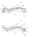
- FIG. 1 an intermediate product 300 with a driving system pickup 100 is shown, which comprises a drive unit 102, a first receiving unit 104 and a second receiving unit 106.
- the driving system receiver 100 is coupled to the left, lower end of a driving system structure 10, that is to say the structure 10A of an escalator with a balustrade 10B, so that it is possible to shift to the left, in the direction of the arrow L.
- the in the FIGS. 3A and 3B Drive unit 102 which is shown on a larger scale and may also be referred to as a tension element or self-propelled drive element, is a towing vehicle with a pair of rolling wheels 102A and a castor wheel arrangement 102B in the present exemplary embodiment. Furthermore, the drive unit 102 comprises an actuator 102C. On the drive unit 102, a coupling element 102D is fastened, with which the drive unit 102 is coupled directly to the driving system structure 10 to be moved, for example electromagnetically.
- the coupling element 102D is a flexible element that can only be claimed in tension and that is therefore only suitable for pulling the driving system structure 10.
- the coupling element 102D can also be rigid, that is to say a push rod or push-pull rod, so that the drive system structure 10 can also be pushed and steered.
- the receiving units 104 and 106 may each consist of a pair of sub-recording units, and they may be the same or different.
- the receiving units 104, 106 comprise an actual platform 104A, 106A and two respective rolling axes, which are equipped with the roller pairs 104B, 106B. Instead of the pairs of rollers, one or more rollers or one or more runners can be provided.
- Fig. 2 In turn, the driving system sensor 100 with the drive unit 102 and the receiving units 104 and 106 as well as the driving system structure 10 are shown.
- the drive unit 102 is coupled or coupled at the right, upper end of the driving system structure 10, so that the driving system structure 10 can be pulled to the right, in the direction of the arrow R.
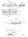
- FIGS. 4A to 8B refer to a second embodiment of the invention Fahrsystemetzdozenss.
- Fig. 4A shows this Fahrsystemetzsacrificing 200, but without second receiving unit, with a part of the driving system structure 10 including balustrade 10B and structure 10A.
- the Fahrsystemier choir 200 includes a drive unit 202 in the form of a conventional forklift truck or self-propelled heavy-duty forklift, which in the Figs. 5A and 5B is shown in more detail.
- the driving system sensor 200 comprises a drive unit 202 with a first docked receiving unit 204, and usually at least one second receiving unit, not shown.
- the FIGS. 6A and 6B shows the drive unit 202 with the docked receiving unit 204th
- the receiving unit 204 is movably mounted on four heavy duty rollers 208.
- docking means are provided, in the present example a mandrel or plug-in bolt on the drive unit 202.
- the receiving unit 204 has in the present embodiment, several, namely four, mandrel shots.
- the drive unit 202 docks on the receiving unit 204 by her mandrel or pin alternatively engages in one of the four mandrel shots. This makes it possible to move the receiving unit 204 by train and push in different and different directions.
- the receiving unit 204 further comprises transport foot receptacles 220.
- the Transportfussingn 220 are formed as Transportfussklauen or Transportfussgabeln.
- the transport foot receptacles 220 serve to receive corresponding transport feet 20 of the moving system structure 10 to be moved and can also be height, depth and width adjustable.
- the driving system structure usually by means of a hoist or overhead crane or gantry crane, lowered onto the receiving unit 204, such that their transport feet 20 are sunk into the Transportfussingn 220 (see Fig. 8A ).
- the transport foot receptacles 220 prevent a vertical downward movement and a horizontal slippage of the driving system structure 10 from the receiving unit 204.
- the transport foot 20 of the driving system structure 10 is encompassed by the transport foot receptacle 220, because the recess of the transport foot receptacle 220 and the transport foot 20 are both longitudinally also coordinated in the transverse direction with respect to shape and size or formed complementary.
- the fork-shaped or claw-shaped Transportfussbefore 220 prevents forward and backward movement of the driving system structure 10 relative to the receiving unit 204.
- the width of the Transportfussam 220 is, with some play, adapted to the transport foot 20, so that a lateral movement or transverse movement of the Driving system structure 10 relative to the receiving unit 204 is impossible.
- lateral boundary plates prevent sliding away or slipping of the transport foot 20 in the transverse direction.
- the Transportfussingn 220 are mounted in pairs on the actual receiving platform 205 of the Fahrsystemauf choirs 204 so that each pair of Transportfussingn 220 left and right transport foot 20 of the driving system structure 10, with left and right on the direction of travel of the finished driving system refer (see Fig. 8A ).
- the receiving unit 204 is wide-adjustable.
- the actual receiving platform 205 and, on the other hand, the transport foot receivers 220 are designed such that the latter, depending on the width of the driving system structure 10 to be picked up or transferred, can be arranged at different widths or at different mutual distances on the receiving platform 205 ,
- Particularly simple is an arrangement in which the Transportfussingn 220 only have to be repositioned or reversed or screwed. This also has the advantage that defective or worn Transportfussingn 220 can be easily replaced.
- the transport foot receptacles 220 may also be mounted laterally adjustable and lockable in guides on the receiving platform 205, such that a stepless or stepped width adjustment is possible.
- the transport foot receptacles 220 and the transport feet 20 are formed so that a slight adjustment of the altitude and / or inclination or horizontal position of the driving system structure 10 is possible.
- the receiving units 204 of the driving system receivers may be designed such that they serve as stationary supports for the driving system structures 10 not only during the transport phases as mobile but also during the assembly phases.
- the assembly stations may also contain their own, stationary receiving units.
- foot receptacles or transport foot receptacles 220 are preferably provided, which are configured and can be arranged so that they can receive the transport feet 20.
- the mounting stations may include stationary receiving units 204, but without foot receptacles.
- the driving system structures 10 are then stored for the assembly phases together with their transport feet 20 and the Transportfussabilityn 220 or without the Transportfussabilityn 220 in the assembly stations on the local stationary receiving units 204. Furthermore, the driving system structure 10 and / or the transport foot 20 rests on the receiving platform 205.
- the feet or transport feet 20 and the foot receptacles 220 in particular if they serve not only as a mobile Transportfussagen during the transport phases, but also as a stationary Lewisagen during the assembly phases are preferably, but not necessarily, height adjustable. This ensures that the altitude of the individual foot areas of the driving system structures 10 is adjusted or adjusted.
- the height adjustment can be achieved with an arrangement in which the foot receptacle 220 has two at an angle W1 and symmetrically to a vertical plane V arranged wings T.
- the male Transportfuss 20 is complementary and is located on these wings T at least partially on or on.
- the distance of the wings T from the vertical plane V can be changed. With a reduction of this distance, the transport foot 20 is raised, with an increase of this distance, the transport foot 20 is lowered, wherein the vertical axis of Transport foot 20 remains in place, so that no horizontal displacement of the transport foot 20 and thus the driving system structure 10 occurs.
- An additional advantage of this arrangement is that the sinking of the transport feet 20 is facilitated, since by the inclined wings T of the foot receptacles 220 to some extent a self-centering effect is achieved.
- the receiving unit 204 is further equipped with two attached to the actual receiving platform 205 sliders 230.
- only one sling bar if necessary.
- One or more eye bolts or other means may be provided, in which a lifting crane can engage to transport the Fahrsystemaufsacrificing 200 using a hoist, such as a crane.
- the slingbars may also be configured and arranged to be gripped and lifted by a forklift truck.
- Fig. 7C is an essential aspect indicated by the arrows B1 and B2. Namely, in a presently preferred embodiment, the receiving unit 204 according to the invention can be moved both forward (in the direction B2) and sideways (in the direction B1). This eliminates the need for time-consuming and lengthy maneuvering of the very large and heavy loads or loads.
- Fig. 9 This type of transverse displacement is used at the lower end of the mounting location where a shift from left to right takes place. Of course, an opposite movement to B1 and B2 is also easy, effortlessly possible, so backwards and to the other side.
- Fig. 8A and Fig. 8B show an intermediate product 300, namely the receiving unit 204 with the driving system structure arranged thereon 10, wherein the transport feet 20 are arranged in the Transportfussingn 220.
- Fig. 9 shows an assembly location 400 during a transfer phase.
- the assembly site 400 includes a plurality of assembly stations 410 configured to perform station-specific, different assembly steps, wherein each assembly step may include individual substeps.
- the assembly station 410 also includes a plurality of driving system receivers 200 and a control system 430 that controls the operations in the assembly site 400 fully or partially automated.
- a hoist 420 for example a gantry crane, overhead crane or slewing crane serves to sink the driving system structures 10 into the driving system receivers 200 and to remove them again from the driving system receivers 200. Other hoists are not necessary, so that the mounting location 400 does not require complex building structures, which is a clear advantage over conventional assembly halls.
- a first driving system pickup 200 in Fig. 9 shown at the top left is provided to receive a ride system structure 10. Further driving system receivers 200 have already picked up driving system structures 10 and together with them form intermediate products 300.
- the intermediates 300 are supplied to the individual assembly stations 410 during the transfer phases by means of the autonomously movable driving system receivers 200 and / or removed therefrom.
- the intermediates 300 can be both longitudinally and transversely thereto, as between the in Fig. 9 below shown assembly stations to be transferred.
- the intermediates 300 are stationary in the assembly stations 410.
- the driving system structure 10 is removed from the respectively finished intermediate product 300, which can be done with the aid of the already mentioned hoist 420, as is shown in FIG Fig. 9 shown on the top right.
- the control system 430 serves to control the entire process of manufacturing assembly.
- the control system 430 may also include only parts of the mounting location 400, for example, only the mounting stations 410.
- the controller 430 may control the assembly stations 410 and also semi-robots and robots located in the assembly stations 410, such as welding robots, spot welding robots, glass placement robots, etc.
Landscapes
- Escalators And Moving Walkways (AREA)
- Automatic Assembly (AREA)
Description
- Die Erfindung betrifft einen Fahrsystemaufnehmer nach dem unabhängigen Patentanspruch 1, und ein Verfahren zum Zusammenbauen von Fahrsystemen nach dem unabhängigen Patentanspruch 9.
Als Fahrsysteme werden im Rahmen der vorlegenden Beschreibung Fahrtreppen und Fahrsteige bezeichnet. Fahrsystemaufnehmer im Sinne der Erfindung werden insbesondere bei der getakteten Fertigungsmontage von Serien von Fahrsystemen in Fertigungsstrassen benutzt, wie in der Patentanmeldung 05111810.7 derselben Anmelderin beschrieben. Dabei durchläuft jedes Fahrsystem bzw. dessen Fahrsystemstruktur eine Vielzahl von Montagestationen. Serien von Fahrsystemen können mehrere Fahrsysteme umfassen, typischerweise zwischen drei und vierzig Fahrsysteme. Die Fahrsystemstrukturen, die gleichzeitig in Fertigungsmontage sind, können gleich oder unterschiedlich lang bzw. hoch bzw. breit sein. In jeder Montagestation wird während einer Montagephase ein spezifischer Montageschritt, der wiederum Teilschritte umfassen kann, durchgeführt. Diese Montagephasen dauern vorzugsweise in den verschiedenen Montagestationen mindestens annähernd gleich lange, zum Beispiel etwa drei Stunden. Sind die Montageschritte in allen Montagestationen beendet, so folgt eine Transferphase. Während der Transferphase werden Fahrsystemstrukturen, deren Fertigungsmontage beendet ist, abgeführt, während weitere Fahrsystemstrukturen in die jeweils nächstfolgende Montagestation verbracht werden und man eine "neue" Fahrsystemstruktur zuführt, deren Fertigungsmontage erst beginnt.
Für eine rationelle und getaktete Fertigung ist es wichtig, dass der Transfer aller involvierten Fahrsystemstrukturen möglichst synchron abläuft und von möglichst kurzer Dauer ist, und zwar auch dann, wenn die einzelnen Fahrsysteme sich von der Länge her unterscheiden. - Eine solche kurze und synchrone Transferphase kann mit herkömmlichen Mitteln nicht realisiert werden. Ein Fahrsystemaufnehmer gemäß dem Oberbegriff des Anspruchs 1 ist aus der
JP 11199165 US-6,808,057 ist lediglich eine Einrichtung mit einer an einer Ladebrücke eines Lastwagens montierten Treppe bekannt, deren Neigungswinkel verstellbar ist, und aus derUS-4,260,318 ist eine Einrichtung zum Bewegen vormontierter Fahrtreppen an ihrem Installationsort bekannt. Beide Einrichtungen eignen sich aber, auch mit kleineren Umkonstruktionen, nicht für den oben beschriebenen Transfer von in Fertigungsmontage begriffenen Fahrsystemen, da höhere Anforderungen an Stabilität, Steifigkeit, Manövrierbarkeit, Genauigkeit sowie Flexibilität in der Anwendung gestellt sind. - Aufgabe der Erfindung ist es, die Fertigungsmontage von Fahrsystemstrukturen zu rationalisieren und insbesondere
- einen Fahrsystemaufnehmer zu schaffen, mit welchem ein Fahrsystem während einer Transferphase zu- und von einer Montagestation weggeführt werden kann und
- ein Verfahren zum Zusammenbauen von Fahrsystemen zu schaffen.
- Die Lösung dieser Aufgabe erfolgt erfindungsgemäss
- für den Fahrsystemaufnehmer durch die Merkmale des unabhängigen Patentanspruchs 1und
- für das Verfahren durch die Merkmale des unabgängigen Patentanspruchs 9.
- Bevorzugte Einzelheiten und Weiterbildungen der erfindungsgemässen Gegenstände sind durch die abhängigen Patentansprüche definiert.
- Der Fahrsystemaufnehmer nach der Erfindung umfasst eine Antriebseinheit und mindestens eine erste und eine zweite Aufnahmeeinheit. Als Aufnahmeeinheit kann eine Aufnahmeplattform mit Rollen oder ggfs. mit Kufen eingesetzt werden.
- Die Antriebseinheit kann ein Zugwagen, vorzugsweise mit Elektroantrieb, sein. Ein solcher Zugwagen kann beispielsweise zwei Achsen aufweisen und mittels einer Schubstange oder eines flexiblen Elementes, zum Beispiel einer Kette oder eines Seiles, an die Fahrsystemstruktur ankuppelbar sein, so dass die Antriebseinheit unmittelbar mit der Fahrsystemstruktur in Verbindung steht.
Anstelle eines solchen Zugwagens kann auch eine Art Hubgabelstapler verwendet werden, der an einer als Aufnahmeeinheit dienenden Aufnahmeplattform mit Schwerlastrollen andockt. Die Fahrsystemstruktur wird von dieser Aufnahmeplattform und einer weiteren Aufnahmeeinheit aufgenommen. In diesem Falle steht die Antriebseinheit mittelbar über die Aufnahmeplattform mit der Fahrsystemstruktur in Verbindung. - Der Fahrsystemaufnehmer dient sowohl dazu, die Fahrsystemstruktur autonom zu transferieren und sie dadurch beispielsweise Montagestationen zuzuführen und sie daraus zu entfernen, als auch dazu, in Montagestationen als Auflager für die Fahrsystemstruktur zu dienen, um diese stationär zu halten und zu fixieren bzw. abzustellen. Der Fahrsystemaufnehmer und die Fahrsystemstruktur bilden zumindest während der Montage eine Einheit, die hier als Zwischenprodukt bezeichnet wird.
- Der Montagestandort kann beispielsweise eine Montagehalle, Fabrikhalle, Portalhalle, Freiluftplatz, Traglufthalle oder eine Überdachhalle bzw. Überdachung sein. Der Montagestandort umfasst eine Anzahl von Montagestationen, eine Vielzahl von Fahrzeugaufnehmern sowie ein Steuerungssystem. Die Montagestationen werden nacheinander und üblicherweise in vorgegebener Reihenfolge von den Zwischenprodukten besucht, und in jeder Montagestation wird während einer vorgegebenen Montageperiode ein stationsspezifischer Montageschritt an einer Fahrsystemstruktur durchgeführt. Nach Beendigung dieses Montageschrittes werden die Zwischenprodukte während einer Transferperiode in die darauf folgenden Montagestationen transferiert. Das Steuerungssystem sorgt dafür, dass die Montageschritte und die Transferschritte für alle in Fertigungsmontage begriffenen Zwischenprodukte gleichzeitig und getaktet durchgeführt werden. Hierbei berücksichtigt das Steuerungssystem, dass die Zwischenprodukte bzw. die Fahrsysteme unterschiedlich ausgebildet sind. Hierbei sind die Montageschritte in den einzelnen Montagestationen zwar jeweils stationsspezifisch, aber so steuerbar, dass sie an das jeweilig dort befindliche Zwischenprodukt angepasst sind. Damit erhält man ein Montagesystem, in welchem die Vorteile und Eigenschaften einer Einzelfertigung mit den Vorteilen und Eigenschaften einer Serienfertigung kombiniert sind.
- Weitere Einzelheiten und Vorteile der Erfindung werden im Folgenden an Hand von Ausführungsbeispielen und mit Bezug auf die Zeichnung erläutert. Es zeigen:
- Fig. 1
- ein erstes Ausführungsbeispiel eines Zwischenproduktes mit einem Fahrsystemaufnehmer nach der Erfindung und einer Fahrsystemstruktur, wobei der Fahrsystemaufnehmer an eine Fahrsystemstruktur für eine Fahrtreppe angekuppelt ist, während einer Bewegung in eine erste Richtung, in einer vereinfachten Darstellung, von der Seite gesehen;
- Fig. 2
- das in
Fig. 1 dargestellten Zwischenprodukt, während seiner Bewegung in die Gegenrichtung, in gleicher Darstellung wieFig. 1 ; - Fig. 3A
- eine Antriebseinheit des in
Fig. 1 dargestellten Fahrsystemaufnehmers, von der Seite; - Fig. 3B
- die in
Fig. 3A dargestellte Antriebseinheit, von oben; - Fig. 4A
- ein zweites Ausführungsbeispiel des Fahrsystemaufnehmers nach der Erfindung, von der nur die Antriebseinheit und die erste Aufnahmeeinheit dargestellt sind, mit einem Teil einer Fahrsystemstruktur, von der Seite;
- Fig. 4B
- die in
Fig. 4A eingekreiste Einzelheit bzw. Detail, in vergrössertem Massstab; - Fig. 5A
- die Antriebseinheit des in
Fig. 4 dargestellten Fahrsystemaufnehmers, von der Seite; - Fig. 5B
- die in
Fig. 5A dargestellte Antriebseinheit, von oben; - Fig. 6A
- die in den
Fig. 5A und 5B dargestellte Antriebseinheit mit der angedockten ersten Aufnahmeeinheit, von der Seite; - Fig. 6B
- die in
Fig. 6A dargestellte Antriebseinheit mit Aufnahmeeinheit, von oben; - Fig. 7A
- die in
Fig. 6A und 6B dargestellte Aufnahmeeinheit, von vorne; - Fig. 7B
- die in
Fig. 7A dargestellte Aufnahmeeinheit, von oben; - Fig. 7C
- die in
Fig. 7A und 7B dargestellte Aufnahmeeinheit, von der Seite; - Fig. 8A
- ein Zwischenprodukt, umfassend die in den
Fig. 7A bis 7C dargestellte Aufnahmeeinheit und eine Fahrsystemstruktur, von hinten bzw. vorne ohne Antriebseinheit; - Fig. 8B
- die in
Fig. 8A dargestellte Aufnahmeeinheit, von der Seite, vorne und hinten an der Fahrsystemstruktur und ohne Antriebseinheit; und - Fig. 9
- eine Montagestation nach der Erfindung, in stark vereinfachter Darstellung.
- Gleich wirkende Bauteile sind nicht in allen Figuren mit den gleichen Bezugszeichen versehen. Bezeichnungen wie oben, unten, rechts, links beziehen sich auf die Darstellung der Bauteile in den Figuren oder die Bewegungsrichtung des Fahrsystemaufnehmers.
- In
Fig. 1 ist ein Zwischenprodukt 300 mit einem Fahrsystemaufnehmer 100 gezeigt, der eine Antriebseinheit 102, eine erste Aufnahmeeinheit 104 und eine zweite Aufnahmeeinheit 106 umfasst. Der Fahrsystemaufnehmer 100 ist an das linke, untere Ende einer Fahrsystemstruktur 10, dass heisst an die Struktur 10A einer Fahrtreppe mit einer Balustrade 10B, angekoppelt, so dass eine Verschiebung nach links, in Richtung des Pfeils L, möglich ist. - Die in den
Fig. 3A und 3B in grösserem Massstab dargestellte Antriebseinheit 102, die auch als Zugelement bzw. selbstfahrendes Antriebselement bezeichnet werden kann, ist im vorliegenden Ausführungsbeispiel ein Zugwagen mit einem Rollradpaar 102A und einer Lenkrollenanordnung 102B. Im Weiteren umfasst die Antriebseinheit 102 ein Betätigungsglied 102C. An der Antriebseinheit 102 ist ein Kupplungselement 102D befestigt, mit welchem die Antriebseinheit 102 unmittelbar an die zu bewegende Fahrsystemstruktur 10 angekuppelt bzw. angekoppelt ist, zum Beispiel elektromagnetisch. - Das Kupplungselement 102D ist beim vorliegenden Ausführungsbeispiel ein flexibles Element, das nur auf Zug beanspruchbar ist und das sich daher nur zum Ziehen der Fahrsystemstruktur 10 eignet. Das Kupplungselement 102D kann auch starr sein, also eine Schubstange bzw. Schubzugstange, so dass die Fahrsystemstruktur 10 auch geschoben und gelenkt werden kann.
- Die Aufnahmeeinheiten 104 und 106 können je aus einem Paar Teil-Aufnahmeinheiten bestehen, und sie können gleich oder unterschiedlich ausgebildet sein. Die Aufnahmeeinheiten 104, 106 umfassen eine eigentliche Plattform 104A, 106A und jeweils zwei Rollachsen, die mit den Rollenpaaren 104B, 106B bestückt sind. Anstelle der Rollenpaare kann auch eine oder mehreren Walzen oder eine oder mehreren Kufen vorgesehen sein.
- In
Fig. 2 sind wiederum der Fahrsystemaufnehmer 100 mit der Antriebseinheit 102 und den Aufnahmeeinheiten 104 und 106 sowie die Fahrsystemstruktur 10 gezeigt. Die Antriebseinheit 102 ist am rechten, oberen Ende der Fahrsystemstruktur 10 angekuppelt bzw. angekoppelt, so dass sich die Fahrsystemstruktur 10 nach rechts, in Richtung des Pfeils R, ziehen lässt. - Die
Figuren 4A bis 8B beziehen sich auf ein zweites Ausführungsbeispiel des erfindungsgemässen Fahrsystemaufnehmers.Fig. 4A zeigt diesen Fahrsystemaufnehmer 200, jedoch ohne zweite Aufnahmeeinheit, mit einem Teil der Fahrsystemstruktur 10 samt Balustrade 10B und Struktur 10A. - Der Fahrsystemaufnehmer 200 umfasst eine Antriebseinheit 202 in Form eines herkömmlichen Hubgabelstaplers bzw. selbstfahrenden Schwerlast-Hubgabelstaplers, der in den
Fig. 5A und 5B genauer dargestellt ist. - Im Weiteren umfasst der Fahrsystemaufnehmer 200 eine Antriebseinheit 202 mit einer ersten, angedockten Aufnahmeeinheit 204, und üblicherweise mindestens eine zweite, nicht dargestellte Aufnahmeeinheit. Die
Fig. 6A und 6B zeigt die Antriebseinheit 202 mit der angedockten Aufnahmeeinheit 204. - Einzelheiten der Aufnahmeeinheit 204 sind aus den
Fig. 7A bis 7C ersichtlich. Die Aufnahmeeinheit 204, im Wesentlichen eine Aufnahmeplattform, ist auf vier Schwerlastrollen 208 fahrbar gelagert. Um die Antriebseinheit 202 mit der Aufnahmeeinheit 204 zu verbinden, sind Andockmittel vorgesehen, im vorliegenden Beispiel ein Dorn bzw. Einsteckbolzen an der Antriebseinheit 202. Komplementäre Dornaufnahmen oder Laschen und/oder Ösen bzw. Bügel oder Ringe bzw. Ringschrauben oder Kettenglieder bzw. Karabiner befinden sich an der Aufnahmeeinheit 204. Die Aufnahmeeinheit 204 besitzt im vorliegenden Ausführungsbeispiel mehrere, nämlich vier, Dornaufnahmen. Die Antriebseinheit 202 dockt an die Aufnahmeeinheit 204 an, indem ihr Dorn bzw. Einsteckbolzen alternativ in eine der vier Dornaufnahmen eingreift. Dadurch ist es möglich, die Aufnahmeeinheit 204 durch Zug und Schub in verschiedene und verschiedenste Richtungen zu bewegen. - Die Aufnahmeeinheit 204 weist im Weiteren Transportfussaufnahmen 220 auf. Die Transportfussaufnahmen 220 sind als Transportfussklauen oder Transportfussgabeln ausgebildet. Die Transportfussaufnahmen 220 dienen dazu, entsprechende Transportfüsse 20 der zu bewegenden Fahrsystemstruktur 10 aufzunehmen und können auch höhen-, tiefen- und breitenverstellbar sein. Für eine erste Transferphase wird die Fahrsystemstruktur 10, üblicherweise mittels eines Hebezeuges bzw. Brückenkranes bzw. Portalkranes, auf die Aufnahmeeinheit 204 abgesenkt, derart, dass ihre Transportfüsse 20 in die Transportfussaufnahmen 220 eingesenkt werden (siehe
Fig. 8A ). Die Transportfussaufnahmen 220 verhindern eine vertikale Abwärtsbewegung und ein horizontales Verrutschen bzw. Weggleiten der Fahrsystemstruktur 10 von der Aufnahmeeinheit 204. Der Transportfuss 20 der Fahrsystemstruktur 10 wird von der Transportfussaufnahme 220 umgriffen, denn die Ausnehmung der Transportfussaufnahme 220 und der Transportfuss 20 sind sowohl in Längsrichtung wie auch in Querrichtung bezüglich Form und Grösse aufeinander abgestimmt bzw. komplementär ausgebildet. Im vorliegenden Ausführungsbeispiel verhindert die gabelförmige oder klauenförmige Transportfussaufnahme 220 eine Vor- und Rückwärtsbewegung der Fahrsystemstruktur 10 relativ zur Aufnahmeeinheit 204. Auch die Breite der Transportfussaufnahme 220 ist, mit etwas Spiel, dem Transportfuss 20 angepasst, so dass auch eine seitliche Bewegung bzw. Querbewegung der Fahrsystemstruktur 10 relativ zur Aufnahmeeinheit 204 unmöglich ist. Ausserdem verhindern seitliche Begrenzungsbleche ein Weggleiten bzw. Verrutschen des Transportfusses 20 in Querrichtung. - Die Transportfussaufnahmen 220 sind paarweise auf der eigentlichen Aufnahmeplattform 205 des Fahrsystemaufnehmers 204 angebracht, so dass jedes Paar der Transportfussaufnahmen 220 einen linken und einen rechten Transportfuss 20 der Fahrsystemstruktur 10 aufnehmen kann, wobei sich links und rechts auf die Fahrtrichtung des fertigen Fahrsystems beziehen (siehe
Fig. 8A ). - Da die zu bewegenden Fahrsystemstrukturen 10 nicht alle die gleiche Breite aufweisen, ist die Aufnahmeeinheit 204 breitenanpassbar. Zu diesem Zwecke sind einerseits die eigentliche Aufnahmeplattform 205 und anderseits die Transportfussaufnahmen 220 so ausgebildet, dass die Letzteren, je nach der Breite der aufzunehmenden bzw. zu transferierenden Fahrsystemstruktur 10, in verschiedenen Breiten bzw. in verschiedenen gegenseitigen Abständen an der Aufnahmeplattform 205 angeordnet werden können. Besonders einfach ist eine Anordnung, bei welcher die Transportfussaufnahmen 220 nur umgesteckt bzw. umgeklemmt bzw. umgeschraubt werden müssen. Dies hat auch den Vorteil, dass defekte oder abgenützte Transportfussaufnahmen 220 in einfacher Weise ersetzt werden können. Die Transportfussaufnahmen 220 können auch seitlich verstellbar und arretierbar in Führungen an der Aufnahmeplattform 205 gelagert sein, derart, dass eine stufenlose oder abgestufte Breiteneinstellung möglich ist.
- Vorzugsweise sind die Transportfussaufnahmen 220 und die Transportfüsse 20 so ausgebildet, dass eine geringfügige Justierung der Höhenlage und/oder Schräglage bzw. Horizontallage der Fahrsystemstruktur 10 möglich ist.
- Die Aufnahmeeinheiten 204 der Fahrsystemaufnehmer können so ausgebildet sein, dass sie nicht nur während den Transportphasen als mobile, sondern auch während den Montagephasen als stationäre Auflager für die Fahrsystemstrukturen 10 dienen.
- Alternativ können die Montagestationen auch eigene, stationäre Aufnahmeeinheiten enthalten. Hierbei sind vorzugsweise Fussaufnahmen oder Transportfussaufnahmen 220 vorgesehen, die so ausgebildet sind und so angeordnet werden können, dass sie die Transportfüsse 20 aufnehmen können.
- In einer weiteren Ausführungsart können die Montagestationen stationäre Aufnahmeeinheiten 204, jedoch ohne Fussaufnahmen, enthalten. Die Fahrsystemstrukturen 10 werden dann für die Montagephasen zusammen mit ihren Transportfüssen 20 und den Transportfussaufnahmen 220 oder ohne die Transportfussaufnahmen 220 in den Montagestationen auf den dortigen stationären Aufnahmeeinheiten 204 gelagert.
Weiters liegt die Fahrsystemstruktur 10 und/oder der Transportfuss 20 auf der Aufnahmeplattform 205 auf.
Die Füsse bzw. Transportfüsse 20 und die Fussaufnahmen 220, insbesondere wenn sie nicht nur als mobile Transportfussaufnahmen während der Transportphasen, sondern auch als stationäre Fussaufnahmen während der Montagephasen dienen, sind vorzugsweise, aber nicht zwingend, höhenverstellbar. Damit wird erreicht, dass die Höhenlage der einzelnen Fussbereiche der Fahrsystemstrukturen 10 eingestellt bzw. justiert wird. - Die Höhenverstellbarkeit kann erreicht werden mit einer Anordnung, bei der die Fussaufnahme 220 zwei unter einem Winkel W1 und symmetrisch zu einer Vertikalebene V angeordnete Tragflächen T aufweist. Der aufzunehmende Transportfuss 20 ist komplementär ausgebildet und liegt an diesen Tragflächen T mindestens teilweise an bzw. auf. Der Abstand der Tragflächen T von der Vertikalebene V kann verändert werden. Bei einer Verringerung dieses Abstandes wird der Transportfuss 20 angehoben, bei einer Vergrösserung dieses Abstandes wird der Transportfuss 20 gesenkt, wobei die vertikale Achse des Transportfusses 20 am Ort bleibt, so dass keine horizontale Verschiebung des Transportfusses 20 und damit der Fahrsystemstruktur 10 eintritt. Ein zusätzlicher Vorteil dieser Anordnung liegt darin, dass das Einsenken der Transportfüsse 20 erleichtert wird, da durch die geneigten Tragflächen T der Fussaufnahmen 220 gewissermassen eine selbstzentrierende Wirkung erreicht ist.
- Die Aufnahmeeinheit 204 ist im Weiteren mit zwei an der eigentlichen Aufnahmeplattform 205 angebrachten Hebebügeln 230 bestückt. Alternativ könnten auch nur ein Hebebügel, ggfs. auch eine oder mehrere Augenschrauben oder andere Mittel vorgesehen sein, in welche ein Hebekran eingreifen kann, um den Fahrsystemaufnehmer 200 mit Hilfe eines Hebezeuges, wie eines Kranes, zu transportieren. Die Hebebügel können auch so ausgebildet und angeordnet sein, dass sie von einem Hubgabelstapler ergriffen und angehoben werden können.
- In
Fig. 7C ist ein wesentlicher Aspekt durch die Pfeile B1 und B2 angedeutet. Die erfindungsgemässe Aufnahmeeinheit 204 kann nämlich in einer gegenwärtig bevorzugten Ausführungsform sowohl vorwärts (in Richtung B2) als auch seitwärts (in Richtung B1) bewegt werden. Damit erübrigt sich ein aufwendiges und langwieriges Manövrieren der sehr grossen und schweren Last bzw. Lasten. InFig. 9 kommt diese Art der Querverschiebung am unteren Ende des Montagestandorts zur Anwendung wo eine Verschiebung von links nach rechts erfolgt. Natürlich ist eine gegenläufige Bewegung zu B1 und B2 auch leicht, mühelos möglich, also rückwärts und zur anderen Seite. -
Fig. 8 A und Fig. 8B zeigen ein Zwischenprodukt 300, nämlich die Aufnahmeeinheit 204 mit der darauf angeordneten Fahrsystemstruktur 10, wobei die Transportfüsse 20 in den Transportfussaufnahmen 220 angeordnet sind. -
Fig. 9 zeigt einen Montagestandort 400 während einer Transferphase. Der Montagestandort 400 umfasst mehrere Montagestationen 410, die dazu ausgelegt sind, stationsspezifische unterschiedliche Montageschritte durchzuführen, wobei jeder Montageschritt einzelne Teilschritte umfassen kann. Zur Montagestation 410 gehören ebenfalls eine Vielzahl von Fahrsystemaufnehmern 200 und ein Steuerungssystem 430, das die Vorgänge in dem Montagestandort 400 vollständig oder teilweise automatisiert steuert. Ein Hebezeug 420, beispielsweise ein Portalkran, Brückenkran oder Schwenkkran dient dazu, die Fahrsystemstrukturen 10 in die Fahrsystemaufnehmer 200 einzusenken und sie wieder aus den Fahrsystemaufnehmern 200 zu entfernen. Weitere Hebezeuge sind nicht notwendig, so dass der Montagestandort 400 keiner aufwändigen Gebäudestrukturen bedarf, was ein deutlicher Vorteil gegenüber herkömmlichen Montagehallen ist. - Ein erster Fahrsystemaufnehmer 200, in
Fig. 9 links oben gezeigt, ist bereitgestellt, um eine Fahrsystemstruktur 10 aufzunehmen. Weitere Fahrsystemaufnehmer 200 haben bereits Fahrsystemstrukturen 10 aufgenommen und bilden mit diesen zusammen Zwischenprodukte 300. Die Zwischenprodukte 300 werden während der Transferphasen mittels der autonom beweglichen Fahrsystemaufnehmer 200 in Richtung der Pfeile den einzelnen Montagestationen 410 zugeführt bzw. aus diesen entfernt. Die Zwischenprodukte 300 können sowohl in ihrer Längsrichtung wie auch quer dazu, wie zwischen den inFig. 9 unten gezeigten Montagestationen, transferiert werden. Während der Montagephasen befinden sich die Zwischenprodukte 300 stationär in den Montagestationen 410. Nach Beendigung aller Einzelmontagen wird aus dem jeweils fertig bearbeitete Zwischenprodukt 300 die Fahrsystemstruktur 10 entfernt, was mit Hilfe des schon erwähnten Hebezeuges 420 geschehen kann, wie es inFig. 9 oben rechts dargestellt ist. Das Steuerungssystem 430, symbolisch dargestellt mit strichpunktierten Linien, dient dazu, den gesamten Ablauf der Fertigungsmontage zu steuern. Das Steuerungssystem 430 kann auch nur Teile des Montagestandortes 400, zum Beispiel nur die Montagestationen 410, einbeziehen.
Die Steuerung 430 kann die Montagestationen 410 steuern und auch Halbroboter und Roboter, welche sich in den Montagestationen 410 befinden, wie zum Beispiel Schweissroboter, Punktschweissroboter, Glaseinsetzroboter usw.
Claims (10)
- Fahrsystemaufnehmer (100, 200) zum Aufnehmen und Bewegen einer Fahrsystemstruktur (10) eines Fahrsystems, aufweisend eine fahrbare Antriebseinheit (102, 202), die mit der Fahrsystemstruktur (10) verbindbar ist, um die Fahrsystemstruktur (10) zu bewegen, und mindestens eine erste Aufnahmeeinheit (104, 204) und eine zweite Aufnahmeeinheit (106, 204), die von der Antriebseinheit (102, 202) antreibbar und zum Aufnehmen der Fahrsystemstruktur (10) ausgebildet sind, wobei die Antriebseinheit (202) an eine der Aufnahmeeinheiten (204) andockbar ist oder der Fahrsystemaufnehmer ein Kupplungselement (102D) umfasst, um die Antriebseinheit (102) mit der Fahrsystemstruktur (10) zu verbinden, dadurch gekennzeichnet, dass die Aufnahmeeinheit (104, 106; 204) eine oder mehrere Transportfussaufnahmen (220), beispielsweise Transportfussgabeln oder Transportfussklauen, aufweist, um jeweils einen nach unten weisenden Transportfuss (20) eines Fussbereiches der Fahrsystemstruktur (10) so aufzunehmen, dass er gegen Horizontalverschiebungen und vertikale Abwärtsverschiebungen relativ zur Transportfussaufnahme (220) gesichert ist.
- Fahrsystemaufnehmer (100, 200) nach Anspruch 1, dadurch gekennzeichnet, dass die Transportfussaufnahmen (220) in Paaren, vorzugsweise spiegelsymmetrisch zu einer Längsmittelebene, angeordnet sind, und der Abstand zwischen den Transportfussaufnahmen (220) eines Paares veränderbar ist, um den Fahrsystemaufnehmer (100, 200) breitenmässig an die Fahrsystemstruktur (10) anzupassen.
- Fahrsystemaufnehmer (200) nach Anspruch 1, dadurch gekennzeichnet, dass er Kupplungselement (102D, 202D) aufweist, zum Andocken der Antriebseinheit (202) an der Aufnahmeeinheit (204), mit einem ersten Kupplungselement (102D) an der Antriebseinheit (202) und einem zweiten Kupplungselement (202D) an der Aufnahmeeinheit (204).
- Fahrsystemaufnehmer (200) nach Anspruch 3, dadurch gekennzeichnet, dass die Aufnahmeeinheit (104, 204) mehrere Kupplungselemente (202D) aufweist, die so angeordnet sind, dass das Kupplungselement (102D) alternativ mit einem dieser Kupplungselemente (202D) in Eingriff bringbar ist, um die Aufnahmeeinheit (104, 204) durch die Antriebseinheit (202, 102) in verschiedene und verschiedenste Richtungen zu bewegen.
- Fahrsystemaufnehmer (200) nach Anspruch 4, dadurch gekennzeichnet, dass jedes Kupplungselement (202D) an der Aufnahmeeinheit (104, 204) eine Dornaufnahme oder Bolzenaufnahme und das Kupplungselement (102D) an der Antriebseinheit (202, 102) ein Dorn oder Bolzen ist.
- Fahrsystemaufnehmer (200)nach einem der vorangehenden Ansprüche, dadurch gekennzeichnet, dass die Aufnahmevorrichtung (104, 204) Mittel, beispielsweise Hebebügel oder Hebelaschen (230) aufweist, um ein Eingreifen einer externen Hebevorrichtung oder Hebezeuges oder Kranes zu erlauben.
- Fahrsystemaufnehmer (200) nach Anspruch 1, dadurch gekennzeichnet, dass die Transportfussaufnahme zwei Tragflächen (T) aufweist, die unter einem Fusswinkel (W1) zueinander stehen, deren gegenseitiger Abstand nach oben zunimmt und/oder einstellbar ist, und die dazu bestimmt sind, als Auflager für komplementär geformte, vorzugsweise runde, ballige, tonnige oder kugelige Fussflächen des Transportfusses (20) zu dienen, damit die Tragflächen (T) und die Fussflächen ein Hubsystem für die Höhenjustierung der Fahrsystemstruktur (10) bilden.
- Fahrsystemaufnehmer nach Anspruch 1, dadurch gekennzeichnet, dass die Fussaufnahmen (220) des Fahrsystemaufnehmers (200) höhenverstellbar sind, um die Fahrsystemstruktur (10) für die Montagephase vor der Durchführung des stationsspezifischen Montageschrittes zu horizontieren bzw. horizontal auszurichten.
- Verfahren zum Zusammenbauen von Fahrsystemen, wobei aus je einer Fahrsystemstruktur (10) eines Fahrsystems und je einem Fahrsystemaufnehmer (100, 200) nach einem der Ansprüche 1 bis 8 ein Zwischenprodukt (300) gebildet wird, die Zwischenprodukte (300) aufeinanderfolgend, getaktet und/oder gleichzeitig, einen Montagestandort (400) durchlaufen, wobei während den Transferphasen jedes der Zwischenprodukte (300) zwischen je einer der Montagestationen (410) und der darauffolgenden Montagestation (410) transferiert bzw. transportiert werden, und während den Montagephasen in der jeweiligen Montagestationen (410) ein stationsspezifischer Montageschritte an den Fahrsystemstrukturen (10) der Zwischenprodukte (300) durchgeführt werden.
- Verfahren nach Anspruch 9, dadurch gekennzeichnet, dass ein Steuerungssystem (430) des Montagestandortes (400) die Montagephasen und/oder die Transferphasen zeitlich jeweils mindestens annähernd gleich hält und den Transfer der Zwischenprodukte (300) steuert.
Priority Applications (1)
| Application Number | Priority Date | Filing Date | Title |
|---|---|---|---|
| EP20060125372 EP1795488B1 (de) | 2005-12-07 | 2006-12-05 | Fahrsystemaufnehmer. |
Applications Claiming Priority (3)
| Application Number | Priority Date | Filing Date | Title |
|---|---|---|---|
| EP05111810 | 2005-12-07 | ||
| EP06112651 | 2006-04-13 | ||
| EP20060125372 EP1795488B1 (de) | 2005-12-07 | 2006-12-05 | Fahrsystemaufnehmer. |
Publications (2)
| Publication Number | Publication Date |
|---|---|
| EP1795488A1 EP1795488A1 (de) | 2007-06-13 |
| EP1795488B1 true EP1795488B1 (de) | 2010-04-21 |
Family
ID=37887975
Family Applications (1)
| Application Number | Title | Priority Date | Filing Date |
|---|---|---|---|
| EP20060125372 Not-in-force EP1795488B1 (de) | 2005-12-07 | 2006-12-05 | Fahrsystemaufnehmer. |
Country Status (1)
| Country | Link |
|---|---|
| EP (1) | EP1795488B1 (de) |
Cited By (2)
| Publication number | Priority date | Publication date | Assignee | Title |
|---|---|---|---|---|
| WO2017153314A1 (de) | 2016-03-10 | 2017-09-14 | Inventio Ag | Vorrichtung zum roboterunterstützten herstellen eines tragwerkes für eine personentransportanlage |
| WO2017153324A1 (de) | 2016-03-10 | 2017-09-14 | Inventio Ag | Verfahren zum roboterunterstützten herstellen eines tragwerkes für eine personentransportanlage |
Families Citing this family (1)
| Publication number | Priority date | Publication date | Assignee | Title |
|---|---|---|---|---|
| EP4005963A1 (de) * | 2020-11-30 | 2022-06-01 | Inventio AG | Fahraufnahmevorrichtung für installationsarbeiten |
Family Cites Families (5)
| Publication number | Priority date | Publication date | Assignee | Title |
|---|---|---|---|---|
| JPH0940338A (ja) * | 1995-07-27 | 1997-02-10 | Hitachi Building Syst Co Ltd | エスカレータフレームの搬送装置 |
| JPH11199165A (ja) * | 1998-01-14 | 1999-07-27 | Hitachi Building Systems Co Ltd | エスカレータフレームの階段移動方法 |
| CA2280414C (en) * | 1999-08-03 | 2000-10-31 | Honda Canada Inc. | Zone inspection manufacturing line |
| DE10063136B4 (de) * | 2000-07-10 | 2007-03-08 | Wobben, Aloys, Dipl.-Ing. | Vorrichtung zum Handhaben von Stückgütern |
| US6485247B1 (en) * | 2000-09-28 | 2002-11-26 | The Boeing Company | Engine uplift loader |
-
2006
- 2006-12-05 EP EP20060125372 patent/EP1795488B1/de not_active Not-in-force
Cited By (4)
| Publication number | Priority date | Publication date | Assignee | Title |
|---|---|---|---|---|
| WO2017153314A1 (de) | 2016-03-10 | 2017-09-14 | Inventio Ag | Vorrichtung zum roboterunterstützten herstellen eines tragwerkes für eine personentransportanlage |
| WO2017153324A1 (de) | 2016-03-10 | 2017-09-14 | Inventio Ag | Verfahren zum roboterunterstützten herstellen eines tragwerkes für eine personentransportanlage |
| US10562133B2 (en) | 2016-03-10 | 2020-02-18 | Inventio Ag | Method for a robot-assisted assembly of a supporting structure for a passenger transport system |
| US11407051B2 (en) | 2016-03-10 | 2022-08-09 | Inventio Ag | Device for the robot-assisted manufacturing of a supporting structure for a passenger transport system |
Also Published As
| Publication number | Publication date |
|---|---|
| EP1795488A1 (de) | 2007-06-13 |
Similar Documents
| Publication | Publication Date | Title |
|---|---|---|
| EP3283357B1 (de) | Kit, umfassend ein stelzenfahrzeug und einen dessen transport dienenden anhänger | |
| DE3882917T2 (de) | Vorrichtung und Verfahren zum Heben und Transportieren eines Kraftfahrzeug-Wechselrades. | |
| DE102014100865B4 (de) | Routenzuganhänger mit einem Fahrgestell und einer Transportvorrichtung | |
| DE202013102199U1 (de) | Trailerzuganhänger | |
| DE2657111A1 (de) | Transporter fuer plattengiesstische und verfahren zur herstellung von betonfussbodenplatten unter verwendung solch eines transporters | |
| DE69927070T2 (de) | Lateraler Ausleger für bewegliche Arbeitshebebühne mit vertikalem Mast | |
| WO2008046728A1 (de) | Flurgebundenes transportfahrzeug, insbesondere für den transport von containern | |
| DE102013017062A1 (de) | Fördereinheit und Fördersystem zum Fördern von Ladungsträgern | |
| EP1240071B1 (de) | Hebevorrichtung mit einer führung für lasten | |
| DE1255902B (de) | Verfahren zur Errichtung von Gebaeuden aus vorgefertigten Raumkaesten | |
| DE69403735T2 (de) | Abnehmbares Fahrgestell zum gesteuerten Verfahren einer Last | |
| DE4126728C2 (de) | Hebe- und Förderfahrzeug | |
| DE3332227C2 (de) | Brückenuntersichtgerät | |
| EP1795488B1 (de) | Fahrsystemaufnehmer. | |
| EP3303090B1 (de) | Bausatz für ein modulares gebäude mit einem unterfahrjustierer | |
| EP0832340B1 (de) | Transporteinrichtung zur beförderung von kraftfahrzeugen in gebäuden | |
| DE202006014414U1 (de) | Plattform zum Tragen und Transportieren von Lasten mit abrollbarem Boden und Transportvorrichtung mit einer solchen Plattform | |
| AT520242B1 (de) | Schneefahrzeug | |
| EP1020591B1 (de) | Parksystem | |
| DE19610440C2 (de) | Vorrichtung zum Zusammenbau und zum Verlegen von Spurträger- und Vorbauträgerabschnitten zu einem Brückentragwerk | |
| DE102007049673A1 (de) | Verfahren zum Bergen von Flugzeugen und Flugzeugbergeheber | |
| EP1895965B1 (de) | Personen-fördervorrichtung zur überwindung von höhenunterschieden, insbesondere schwimmbadlifter | |
| EP1795489B1 (de) | Hubsystem. | |
| EP3037377A1 (de) | Schubmaststapler, batteriewechselsystem mit einem schubmaststapler und schubmaststaplerbatteriewechselverfahren | |
| DE4237802C1 (en) | Self chain driven transport system - comprises vehicle units set at intervals on supports with locators for rollers over which runs motor driven chain drive to pull vehicle |
Legal Events
| Date | Code | Title | Description |
|---|---|---|---|
| PUAI | Public reference made under article 153(3) epc to a published international application that has entered the european phase |
Free format text: ORIGINAL CODE: 0009012 |
|
| AK | Designated contracting states |
Kind code of ref document: A1 Designated state(s): AT BE BG CH CY CZ DE DK EE ES FI FR GB GR HU IE IS IT LI LT LU LV MC NL PL PT RO SE SI SK TR |
|
| AX | Request for extension of the european patent |
Extension state: AL BA HR MK YU |
|
| 17P | Request for examination filed |
Effective date: 20071211 |
|
| AKX | Designation fees paid |
Designated state(s): AT BE BG CH CY CZ DE DK EE ES FI FR GB GR HU IE IS IT LI LT LU LV MC NL PL PT RO SE SI SK TR |
|
| 17Q | First examination report despatched |
Effective date: 20080306 |
|
| REG | Reference to a national code |
Ref country code: HK Ref legal event code: DE Ref document number: 1107555 Country of ref document: HK |
|
| GRAP | Despatch of communication of intention to grant a patent |
Free format text: ORIGINAL CODE: EPIDOSNIGR1 |
|
| GRAS | Grant fee paid |
Free format text: ORIGINAL CODE: EPIDOSNIGR3 |
|
| GRAA | (expected) grant |
Free format text: ORIGINAL CODE: 0009210 |
|
| AK | Designated contracting states |
Kind code of ref document: B1 Designated state(s): AT BE BG CH CY CZ DE DK EE ES FI FR GB GR HU IE IS IT LI LT LU LV MC NL PL PT RO SE SI SK TR |
|
| REG | Reference to a national code |
Ref country code: GB Ref legal event code: FG4D Free format text: NOT ENGLISH |
|
| REG | Reference to a national code |
Ref country code: CH Ref legal event code: EP |
|
| REG | Reference to a national code |
Ref country code: IE Ref legal event code: FG4D Free format text: LANGUAGE OF EP DOCUMENT: GERMAN |
|
| REF | Corresponds to: |
Ref document number: 502006006772 Country of ref document: DE Date of ref document: 20100602 Kind code of ref document: P |
|
| REG | Reference to a national code |
Ref country code: RO Ref legal event code: EPE |
|
| REG | Reference to a national code |
Ref country code: NL Ref legal event code: T3 |
|
| REG | Reference to a national code |
Ref country code: ES Ref legal event code: FG2A Ref document number: 2344271 Country of ref document: ES Kind code of ref document: T3 |
|
| LTIE | Lt: invalidation of european patent or patent extension |
Effective date: 20100421 |
|
| REG | Reference to a national code |
Ref country code: HK Ref legal event code: GR Ref document number: 1107555 Country of ref document: HK |
|
| REG | Reference to a national code |
Ref country code: SK Ref legal event code: T3 Ref document number: E 7575 Country of ref document: SK |
|
| PG25 | Lapsed in a contracting state [announced via postgrant information from national office to epo] |
Ref country code: LT Free format text: LAPSE BECAUSE OF FAILURE TO SUBMIT A TRANSLATION OF THE DESCRIPTION OR TO PAY THE FEE WITHIN THE PRESCRIBED TIME-LIMIT Effective date: 20100421 Ref country code: SE Free format text: LAPSE BECAUSE OF FAILURE TO SUBMIT A TRANSLATION OF THE DESCRIPTION OR TO PAY THE FEE WITHIN THE PRESCRIBED TIME-LIMIT Effective date: 20100421 |
|
| REG | Reference to a national code |
Ref country code: IE Ref legal event code: FD4D |
|
| PG25 | Lapsed in a contracting state [announced via postgrant information from national office to epo] |
Ref country code: IS Free format text: LAPSE BECAUSE OF FAILURE TO SUBMIT A TRANSLATION OF THE DESCRIPTION OR TO PAY THE FEE WITHIN THE PRESCRIBED TIME-LIMIT Effective date: 20100821 Ref country code: SI Free format text: LAPSE BECAUSE OF FAILURE TO SUBMIT A TRANSLATION OF THE DESCRIPTION OR TO PAY THE FEE WITHIN THE PRESCRIBED TIME-LIMIT Effective date: 20100421 Ref country code: LV Free format text: LAPSE BECAUSE OF FAILURE TO SUBMIT A TRANSLATION OF THE DESCRIPTION OR TO PAY THE FEE WITHIN THE PRESCRIBED TIME-LIMIT Effective date: 20100421 |
|
| PG25 | Lapsed in a contracting state [announced via postgrant information from national office to epo] |
Ref country code: CY Free format text: LAPSE BECAUSE OF FAILURE TO SUBMIT A TRANSLATION OF THE DESCRIPTION OR TO PAY THE FEE WITHIN THE PRESCRIBED TIME-LIMIT Effective date: 20100512 Ref country code: PL Free format text: LAPSE BECAUSE OF FAILURE TO SUBMIT A TRANSLATION OF THE DESCRIPTION OR TO PAY THE FEE WITHIN THE PRESCRIBED TIME-LIMIT Effective date: 20100421 Ref country code: GR Free format text: LAPSE BECAUSE OF FAILURE TO SUBMIT A TRANSLATION OF THE DESCRIPTION OR TO PAY THE FEE WITHIN THE PRESCRIBED TIME-LIMIT Effective date: 20100722 |
|
| PG25 | Lapsed in a contracting state [announced via postgrant information from national office to epo] |
Ref country code: PT Free format text: LAPSE BECAUSE OF FAILURE TO SUBMIT A TRANSLATION OF THE DESCRIPTION OR TO PAY THE FEE WITHIN THE PRESCRIBED TIME-LIMIT Effective date: 20100823 Ref country code: EE Free format text: LAPSE BECAUSE OF FAILURE TO SUBMIT A TRANSLATION OF THE DESCRIPTION OR TO PAY THE FEE WITHIN THE PRESCRIBED TIME-LIMIT Effective date: 20100421 Ref country code: DK Free format text: LAPSE BECAUSE OF FAILURE TO SUBMIT A TRANSLATION OF THE DESCRIPTION OR TO PAY THE FEE WITHIN THE PRESCRIBED TIME-LIMIT Effective date: 20100421 Ref country code: IE Free format text: LAPSE BECAUSE OF FAILURE TO SUBMIT A TRANSLATION OF THE DESCRIPTION OR TO PAY THE FEE WITHIN THE PRESCRIBED TIME-LIMIT Effective date: 20100421 |
|
| PLBE | No opposition filed within time limit |
Free format text: ORIGINAL CODE: 0009261 |
|
| STAA | Information on the status of an ep patent application or granted ep patent |
Free format text: STATUS: NO OPPOSITION FILED WITHIN TIME LIMIT |
|
| PGFP | Annual fee paid to national office [announced via postgrant information from national office to epo] |
Ref country code: RO Payment date: 20101129 Year of fee payment: 5 |
|
| 26N | No opposition filed |
Effective date: 20110124 |
|
| PGFP | Annual fee paid to national office [announced via postgrant information from national office to epo] |
Ref country code: TR Payment date: 20101125 Year of fee payment: 5 |
|
| BERE | Be: lapsed |
Owner name: INVENTIO A.G. Effective date: 20101231 |
|
| PG25 | Lapsed in a contracting state [announced via postgrant information from national office to epo] |
Ref country code: MC Free format text: LAPSE BECAUSE OF NON-PAYMENT OF DUE FEES Effective date: 20101231 |
|
| PG25 | Lapsed in a contracting state [announced via postgrant information from national office to epo] |
Ref country code: BE Free format text: LAPSE BECAUSE OF NON-PAYMENT OF DUE FEES Effective date: 20101231 |
|
| PGFP | Annual fee paid to national office [announced via postgrant information from national office to epo] |
Ref country code: NL Payment date: 20111228 Year of fee payment: 6 Ref country code: CH Payment date: 20111220 Year of fee payment: 6 |
|
| PG25 | Lapsed in a contracting state [announced via postgrant information from national office to epo] |
Ref country code: HU Free format text: LAPSE BECAUSE OF FAILURE TO SUBMIT A TRANSLATION OF THE DESCRIPTION OR TO PAY THE FEE WITHIN THE PRESCRIBED TIME-LIMIT Effective date: 20101022 Ref country code: LU Free format text: LAPSE BECAUSE OF NON-PAYMENT OF DUE FEES Effective date: 20101205 |
|
| PGFP | Annual fee paid to national office [announced via postgrant information from national office to epo] |
Ref country code: SK Payment date: 20121204 Year of fee payment: 7 |
|
| REG | Reference to a national code |
Ref country code: NL Ref legal event code: V1 Effective date: 20130701 |
|
| REG | Reference to a national code |
Ref country code: CH Ref legal event code: PL |
|
| REG | Reference to a national code |
Ref country code: AT Ref legal event code: MM01 Ref document number: 465118 Country of ref document: AT Kind code of ref document: T Effective date: 20121205 |
|
| PG25 | Lapsed in a contracting state [announced via postgrant information from national office to epo] |
Ref country code: NL Free format text: LAPSE BECAUSE OF NON-PAYMENT OF DUE FEES Effective date: 20130701 Ref country code: CH Free format text: LAPSE BECAUSE OF NON-PAYMENT OF DUE FEES Effective date: 20121231 Ref country code: RO Free format text: LAPSE BECAUSE OF NON-PAYMENT OF DUE FEES Effective date: 20121205 Ref country code: AT Free format text: LAPSE BECAUSE OF NON-PAYMENT OF DUE FEES Effective date: 20121205 Ref country code: LI Free format text: LAPSE BECAUSE OF NON-PAYMENT OF DUE FEES Effective date: 20121231 |
|
| PG25 | Lapsed in a contracting state [announced via postgrant information from national office to epo] |
Ref country code: TR Free format text: LAPSE BECAUSE OF NON-PAYMENT OF DUE FEES Effective date: 20121205 |
|
| REG | Reference to a national code |
Ref country code: SK Ref legal event code: MM4A Ref document number: E 7575 Country of ref document: SK Effective date: 20131205 |
|
| PG25 | Lapsed in a contracting state [announced via postgrant information from national office to epo] |
Ref country code: SK Free format text: LAPSE BECAUSE OF NON-PAYMENT OF DUE FEES Effective date: 20131205 |
|
| REG | Reference to a national code |
Ref country code: FR Ref legal event code: PLFP Year of fee payment: 10 |
|
| REG | Reference to a national code |
Ref country code: FR Ref legal event code: PLFP Year of fee payment: 11 |
|
| REG | Reference to a national code |
Ref country code: FR Ref legal event code: PLFP Year of fee payment: 12 |
|
| PGFP | Annual fee paid to national office [announced via postgrant information from national office to epo] |
Ref country code: FI Payment date: 20171218 Year of fee payment: 12 |
|
| PGFP | Annual fee paid to national office [announced via postgrant information from national office to epo] |
Ref country code: BG Payment date: 20171219 Year of fee payment: 12 |
|
| PG25 | Lapsed in a contracting state [announced via postgrant information from national office to epo] |
Ref country code: FI Free format text: LAPSE BECAUSE OF NON-PAYMENT OF DUE FEES Effective date: 20181205 |
|
| PG25 | Lapsed in a contracting state [announced via postgrant information from national office to epo] |
Ref country code: BG Free format text: LAPSE BECAUSE OF NON-PAYMENT OF DUE FEES Effective date: 20190630 |
|
| PGFP | Annual fee paid to national office [announced via postgrant information from national office to epo] |
Ref country code: CZ Payment date: 20201207 Year of fee payment: 15 Ref country code: FR Payment date: 20201229 Year of fee payment: 15 Ref country code: GB Payment date: 20201228 Year of fee payment: 15 |
|
| PGFP | Annual fee paid to national office [announced via postgrant information from national office to epo] |
Ref country code: IT Payment date: 20201221 Year of fee payment: 15 |
|
| PG25 | Lapsed in a contracting state [announced via postgrant information from national office to epo] |
Ref country code: CZ Free format text: LAPSE BECAUSE OF NON-PAYMENT OF DUE FEES Effective date: 20211205 |
|
| GBPC | Gb: european patent ceased through non-payment of renewal fee |
Effective date: 20211205 |
|
| PG25 | Lapsed in a contracting state [announced via postgrant information from national office to epo] |
Ref country code: GB Free format text: LAPSE BECAUSE OF NON-PAYMENT OF DUE FEES Effective date: 20211205 |
|
| PG25 | Lapsed in a contracting state [announced via postgrant information from national office to epo] |
Ref country code: FR Free format text: LAPSE BECAUSE OF NON-PAYMENT OF DUE FEES Effective date: 20211231 |
|
| PG25 | Lapsed in a contracting state [announced via postgrant information from national office to epo] |
Ref country code: IT Free format text: LAPSE BECAUSE OF NON-PAYMENT OF DUE FEES Effective date: 20211205 |
|
| PGFP | Annual fee paid to national office [announced via postgrant information from national office to epo] |
Ref country code: ES Payment date: 20230120 Year of fee payment: 17 |
|
| PGFP | Annual fee paid to national office [announced via postgrant information from national office to epo] |
Ref country code: DE Payment date: 20221227 Year of fee payment: 17 |
|
| REG | Reference to a national code |
Ref country code: DE Ref legal event code: R119 Ref document number: 502006006772 Country of ref document: DE |
|
| PG25 | Lapsed in a contracting state [announced via postgrant information from national office to epo] |
Ref country code: DE Free format text: LAPSE BECAUSE OF NON-PAYMENT OF DUE FEES Effective date: 20240702 |
|
| PG25 | Lapsed in a contracting state [announced via postgrant information from national office to epo] |
Ref country code: DE Free format text: LAPSE BECAUSE OF NON-PAYMENT OF DUE FEES Effective date: 20240702 |
|
| REG | Reference to a national code |
Ref country code: ES Ref legal event code: FD2A Effective date: 20250124 |
|
| PG25 | Lapsed in a contracting state [announced via postgrant information from national office to epo] |
Ref country code: ES Free format text: LAPSE BECAUSE OF NON-PAYMENT OF DUE FEES Effective date: 20231206 |