EP1795657B1 - Hydraulischer Kreislauf für schwere Baumaschinen - Google Patents
Hydraulischer Kreislauf für schwere Baumaschinen Download PDFInfo
- Publication number
- EP1795657B1 EP1795657B1 EP06008990A EP06008990A EP1795657B1 EP 1795657 B1 EP1795657 B1 EP 1795657B1 EP 06008990 A EP06008990 A EP 06008990A EP 06008990 A EP06008990 A EP 06008990A EP 1795657 B1 EP1795657 B1 EP 1795657B1
- Authority
- EP
- European Patent Office
- Prior art keywords
- swing
- valve
- hydraulic
- switched
- flow path
- Prior art date
- Legal status (The legal status is an assumption and is not a legal conclusion. Google has not performed a legal analysis and makes no representation as to the accuracy of the status listed.)
- Ceased
Links
Images


Classifications
-
- F—MECHANICAL ENGINEERING; LIGHTING; HEATING; WEAPONS; BLASTING
- F15—FLUID-PRESSURE ACTUATORS; HYDRAULICS OR PNEUMATICS IN GENERAL
- F15B—SYSTEMS ACTING BY MEANS OF FLUIDS IN GENERAL; FLUID-PRESSURE ACTUATORS, e.g. SERVOMOTORS; DETAILS OF FLUID-PRESSURE SYSTEMS, NOT OTHERWISE PROVIDED FOR
- F15B21/00—Common features of fluid actuator systems; Fluid-pressure actuator systems or details thereof, not covered by any other group of this subclass
-
- E—FIXED CONSTRUCTIONS
- E02—HYDRAULIC ENGINEERING; FOUNDATIONS; SOIL SHIFTING
- E02F—DREDGING; SOIL-SHIFTING
- E02F9/00—Component parts of dredgers or soil-shifting machines, not restricted to one of the kinds covered by groups E02F3/00 - E02F7/00
- E02F9/20—Drives; Control devices
- E02F9/22—Hydraulic or pneumatic drives
- E02F9/2221—Control of flow rate; Load sensing arrangements
- E02F9/2239—Control of flow rate; Load sensing arrangements using two or more pumps with cross-assistance
-
- E—FIXED CONSTRUCTIONS
- E02—HYDRAULIC ENGINEERING; FOUNDATIONS; SOIL SHIFTING
- E02F—DREDGING; SOIL-SHIFTING
- E02F9/00—Component parts of dredgers or soil-shifting machines, not restricted to one of the kinds covered by groups E02F3/00 - E02F7/00
- E02F9/08—Superstructures; Supports for superstructures
- E02F9/10—Supports for movable superstructures mounted on travelling or walking gears or on other superstructures
- E02F9/12—Slewing or traversing gears
- E02F9/121—Turntables, i.e. structure rotatable about 360°
- E02F9/123—Drives or control devices specially adapted therefor
-
- E—FIXED CONSTRUCTIONS
- E02—HYDRAULIC ENGINEERING; FOUNDATIONS; SOIL SHIFTING
- E02F—DREDGING; SOIL-SHIFTING
- E02F9/00—Component parts of dredgers or soil-shifting machines, not restricted to one of the kinds covered by groups E02F3/00 - E02F7/00
- E02F9/20—Drives; Control devices
- E02F9/22—Hydraulic or pneumatic drives
- E02F9/2278—Hydraulic circuits
- E02F9/2292—Systems with two or more pumps
-
- F—MECHANICAL ENGINEERING; LIGHTING; HEATING; WEAPONS; BLASTING
- F15—FLUID-PRESSURE ACTUATORS; HYDRAULICS OR PNEUMATICS IN GENERAL
- F15B—SYSTEMS ACTING BY MEANS OF FLUIDS IN GENERAL; FLUID-PRESSURE ACTUATORS, e.g. SERVOMOTORS; DETAILS OF FLUID-PRESSURE SYSTEMS, NOT OTHERWISE PROVIDED FOR
- F15B11/00—Servomotor systems without provision for follow-up action ; Circuits therefor
- F15B11/16—Servomotor systems without provision for follow-up action ; Circuits therefor with two or more servomotors
-
- F—MECHANICAL ENGINEERING; LIGHTING; HEATING; WEAPONS; BLASTING
- F15—FLUID-PRESSURE ACTUATORS; HYDRAULICS OR PNEUMATICS IN GENERAL
- F15B—SYSTEMS ACTING BY MEANS OF FLUIDS IN GENERAL; FLUID-PRESSURE ACTUATORS, e.g. SERVOMOTORS; DETAILS OF FLUID-PRESSURE SYSTEMS, NOT OTHERWISE PROVIDED FOR
- F15B11/00—Servomotor systems without provision for follow-up action ; Circuits therefor
- F15B11/16—Servomotor systems without provision for follow-up action ; Circuits therefor with two or more servomotors
- F15B11/17—Servomotor systems without provision for follow-up action ; Circuits therefor with two or more servomotors using two or more pumps
-
- F—MECHANICAL ENGINEERING; LIGHTING; HEATING; WEAPONS; BLASTING
- F15—FLUID-PRESSURE ACTUATORS; HYDRAULICS OR PNEUMATICS IN GENERAL
- F15B—SYSTEMS ACTING BY MEANS OF FLUIDS IN GENERAL; FLUID-PRESSURE ACTUATORS, e.g. SERVOMOTORS; DETAILS OF FLUID-PRESSURE SYSTEMS, NOT OTHERWISE PROVIDED FOR
- F15B2211/00—Circuits for servomotor systems
- F15B2211/20—Fluid pressure source, e.g. accumulator or variable axial piston pump
- F15B2211/205—Systems with pumps
- F15B2211/2053—Type of pump
- F15B2211/20538—Type of pump constant capacity
-
- F—MECHANICAL ENGINEERING; LIGHTING; HEATING; WEAPONS; BLASTING
- F15—FLUID-PRESSURE ACTUATORS; HYDRAULICS OR PNEUMATICS IN GENERAL
- F15B—SYSTEMS ACTING BY MEANS OF FLUIDS IN GENERAL; FLUID-PRESSURE ACTUATORS, e.g. SERVOMOTORS; DETAILS OF FLUID-PRESSURE SYSTEMS, NOT OTHERWISE PROVIDED FOR
- F15B2211/00—Circuits for servomotor systems
- F15B2211/20—Fluid pressure source, e.g. accumulator or variable axial piston pump
- F15B2211/205—Systems with pumps
- F15B2211/20576—Systems with pumps with multiple pumps
-
- F—MECHANICAL ENGINEERING; LIGHTING; HEATING; WEAPONS; BLASTING
- F15—FLUID-PRESSURE ACTUATORS; HYDRAULICS OR PNEUMATICS IN GENERAL
- F15B—SYSTEMS ACTING BY MEANS OF FLUIDS IN GENERAL; FLUID-PRESSURE ACTUATORS, e.g. SERVOMOTORS; DETAILS OF FLUID-PRESSURE SYSTEMS, NOT OTHERWISE PROVIDED FOR
- F15B2211/00—Circuits for servomotor systems
- F15B2211/30—Directional control
- F15B2211/31—Directional control characterised by the positions of the valve element
- F15B2211/3105—Neutral or centre positions
- F15B2211/3116—Neutral or centre positions the pump port being open in the centre position, e.g. so-called open centre
-
- F—MECHANICAL ENGINEERING; LIGHTING; HEATING; WEAPONS; BLASTING
- F15—FLUID-PRESSURE ACTUATORS; HYDRAULICS OR PNEUMATICS IN GENERAL
- F15B—SYSTEMS ACTING BY MEANS OF FLUIDS IN GENERAL; FLUID-PRESSURE ACTUATORS, e.g. SERVOMOTORS; DETAILS OF FLUID-PRESSURE SYSTEMS, NOT OTHERWISE PROVIDED FOR
- F15B2211/00—Circuits for servomotor systems
- F15B2211/70—Output members, e.g. hydraulic motors or cylinders or control therefor
- F15B2211/705—Output members, e.g. hydraulic motors or cylinders or control therefor characterised by the type of output members or actuators
- F15B2211/7051—Linear output members
- F15B2211/7053—Double-acting output members
-
- F—MECHANICAL ENGINEERING; LIGHTING; HEATING; WEAPONS; BLASTING
- F15—FLUID-PRESSURE ACTUATORS; HYDRAULICS OR PNEUMATICS IN GENERAL
- F15B—SYSTEMS ACTING BY MEANS OF FLUIDS IN GENERAL; FLUID-PRESSURE ACTUATORS, e.g. SERVOMOTORS; DETAILS OF FLUID-PRESSURE SYSTEMS, NOT OTHERWISE PROVIDED FOR
- F15B2211/00—Circuits for servomotor systems
- F15B2211/70—Output members, e.g. hydraulic motors or cylinders or control therefor
- F15B2211/705—Output members, e.g. hydraulic motors or cylinders or control therefor characterised by the type of output members or actuators
- F15B2211/7058—Rotary output members
-
- F—MECHANICAL ENGINEERING; LIGHTING; HEATING; WEAPONS; BLASTING
- F15—FLUID-PRESSURE ACTUATORS; HYDRAULICS OR PNEUMATICS IN GENERAL
- F15B—SYSTEMS ACTING BY MEANS OF FLUIDS IN GENERAL; FLUID-PRESSURE ACTUATORS, e.g. SERVOMOTORS; DETAILS OF FLUID-PRESSURE SYSTEMS, NOT OTHERWISE PROVIDED FOR
- F15B2211/00—Circuits for servomotor systems
- F15B2211/70—Output members, e.g. hydraulic motors or cylinders or control therefor
- F15B2211/71—Multiple output members, e.g. multiple hydraulic motors or cylinders
- F15B2211/7114—Multiple output members, e.g. multiple hydraulic motors or cylinders with direct connection between the chambers of different actuators
- F15B2211/7128—Multiple output members, e.g. multiple hydraulic motors or cylinders with direct connection between the chambers of different actuators the chambers being connected in parallel
Definitions
- the present invention relates to a hydraulic circuit for a heavy construction equipment, and in particular to a hydraulic circuit in which a combined operation for a working apparatus can be easily performed so that hydraulic fluid of a confluence valve is supplied to a flow path for a hydraulic cylinder of the working apparatus.
- Hydraulic circuits comprising a work control valve being connected to a first hydraulic pump, a confluence valve connected with a second hydraulic pump and a swing control valve controlling a hydraulic swing motor are known from the following:
- Plural of hydraulic pumps are installed at a conventional hydraulic circuit which has been used at a heavy construction equipment such as an excavator.
- the hydraulic pumps are used at a hydraulic circuit so as to effectively drive a working apparatus, such as a swing apparatus, a traveling apparatus, etc., by properly distributing a hydraulic energy.
- the control valves adapted so as to drive a boom cylinder, an arm cylinder, a bucket cylinder, a hydraulic swing motor for a swing apparatus, a traveling motor for a traveling apparatus, etc. are grouped into at least two control valve groups.
- Various working apparatuses can be concurrently driven in such a manner that the hydraulic fluid of different hydraulic pump is independently supplied to each control valve group.
- the hydraulic circuit adapting a plurality of hydraulic pumps has used a certain technology for combining the hydraulic fluid of the hydraulic pump connected with a certain control valve group.
- a control valve for a boom confluence may be adapted, so that the hydraulic fluids of a hydraulic pump of a group of a boom cylinder control valve and a hydraulic pump of the other group are combined for thereby supplying a lot of hydraulic fluid to the boom cylinder.
- Figure 1 is a side view illustrating a conventional excavator.
- heavy construction equipment such as an excavator performs various works such as excavation, earth and soil collection, etc at a construction sire.
- An upper swing structure 7 is installed at a lower traveling structure 5 of the heavy construction equipment with the upper swing structure 7 including an operation room and a working apparatus.
- the upper swing structure 7 swings about a center axis X with respect to the lower traveling structure 5 based on the swing apparatus 6.
- the work apparatuses of a boom 1, an arm 3 and a bucket 4 work together.
- the work apparatuses operate together with the swing apparatus 6.
- the swing control valve adapted so as to drive the swing apparatus 6 belongs to the group formed of the boom control valve for driving the boom cylinder 2 and the other control valve group, the swing apparatus 6 independently operates without any effects from the operation of the boom cylinder.
- the operation of the swing apparatus 6 may be largely affected by the load applied to the boom cylinder 2.
- the control valve group of the swing apparatus 6 is connected with the control valve group of the boom control valve. Namely, since the hydraulic circuits for controlling a swing apparatus 6 and a boom cylinder 2 are connected with each other, the hydraulic pressure applied to the boom cylinder 2 affects the operation of the swing apparatus 6.
- Figure 2 is a schematic view for describing the combined operation of the boom up movement and the swing apparatus.
- Figure 3 is a schematic view for describing the problems which occur during the combined operation of the boom up movement and the swing apparatus.
- the boom up movement and the swing operation are concurrently performed. As shown in Figure 2 , while the position of the bucket 4 is moved from the point A to the point C through the point B, the swing operation and boom up movement are normally performed. At this time, if the movement of the swing apparatus and boom is maintained with a predetermined speed, the collected earth and soil can be safely transferred to a storing region 8 of the truck.
- the bucket 4 may collide with the rear end of the truck at the point E which is an intermediate point while the bucket 4 is moved from the point A to the point C.
- a skilled worker may stop the operation of the swing apparatus or the speed of the same, while visually checking the up position of the boom in the case that the swing speed increases faster than the speed of the boom up movement.
- a hydraulic circuit for a heavy construction equipment which comprises a work control valve which controls a working apparatus cylinder by supplying or retrieving a hydraulic fluid of a first hydraulic pump through a work unit flow path; a confluence valve which is installed at a parallel flow path connected with a second hydraulic pump and combines a hydraulic fluid of the second hydraulic pump with the work unit flow path based on a positions switch; a swing control valve which is installed at the parallel flow path and controls a hydraulic swing motor by supplying or retrieving a hydraulic fluid of the second hydraulic pump to the plurality of hydraulic swing motors which drive the swing apparatus; and a disconnection valve which is installed at a swing flow path connecting the swing control valve and the swing motor and is position-switched when the confluence valve is position-switched for thereby disconnecting the hydraulic fluid supplied to at least one of the swing motors and at the same time communicating an inlet and an outlet of the disconnected swing motor.
- the confluence valve is position-switched by a pilot signal pressure
- the disconnection valve is position-switched by the pilot signal pressure supplied to the confluence valve.
- the confluence valve is position-switched by an electrical signal
- the disconnection valve is position-switched by the electrical signal supplied to the confluence valve.
- the disconnection valve is position-switched by a manual operation.
- a hydraulic circuit for a heavy construction equipment which comprises a first valve group which includes a work control valve for driving a working apparatus cylinder; a second valve group which is connected with a plurality of hydraulic swing motors through a swing flow path, with the hydraulic swing motors being adapted so as to drive a swing apparatus, and includes a swing control valve for controlling a hydraulic fluid supplied to the swing motor; a confluence valve which is installed between the second valve group and the first valve group and combines part of the hydraulic fluid of the second valve group with the side of the work apparatus cylinder when the position is switched by a pilot signal; and a disconnection valve which is installed at the swing flow path and disconnects the hydraulic fluid supplied to part of the swing motor as the position is switched by the pilot signal inputted into the confluence valve and connects an inlet and an outlet of the disconnected swing motor.
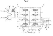
- Fig 4 is a circuit diagram of a hydraulic circuit of a heavy construction equipment according an embodiment of the present invention
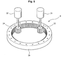
- Figure 5 is a perspective view illustrating a swing apparatus which is driven based on a hydraulic circuit of a heavy construction equipment according to an embodiment of the present invention.
- the hydraulic circuit for a heavy construction equipment includes a first valve group 10 and a second valve group 20 which operate by the hydraulic fluid discharged by a first hydraulic pump 11 and a second hydraulic pump 21.
- the first valve group 10 includes a plurality of control valves disposed at a first parallel flow path 12 connected with the first hydraulic pump 11
- the second valve group 20 includes a plurality of control valves disposed at a second parallel flow path 22 connected with the second hydraulic pump 21.
- the hydraulic circuit for a heavy construction equipment comprises a work control valve 13 which drives a working apparatus cylinder 2 by controlling the hydraulic fluid of the first hydraulic pump 11, a confluence valve 23 installed at the second parallel flow path 22, a swing control valve 30 installed at the second parallel flow path 22, and a disconnection valve 40 installed at the swing flow path 36.
- the work control valve 13 belongs to the first valve group 10, and the swing control valve 30 and the confluence valve 23 belong to the second valve group 20.
- the work control valve 13 is installed at the first parallel flow path 12 and supplies the hydraulic fluid of the first hydraulic pump 11 to the work apparatus cylinder 2 through the work unit flow paths 14 and 15, collects the hydraulic fluid discharged and discharges to the hydraulic tank for thereby driving the work apparatus cylinder 2.
- the work apparatus cylinder 2 corresponds to the work apparatus cylinder like the boom cylinder 2 of Figure 1 .
- the position of the work control valve 13 is switched by a pilot signal P0.
- the confluence valve 23 is installed at the second parallel flow path 22 and combines the hydraulic fluid of the second hydraulic pump 21 with the work unit flow paths 14 and 15. The position of the confluence valve 23 is switched by a pilot signal P1.
- the swing control valve 30 is installed at the second parallel flow path 22 and is connected with a plurality of hydraulic swing motors 31 and 32 through swing flow paths 35 and 36.
- the swing control valve 30 is designed so that the position of the same is switched by a swing pilot signal Ps.
- the swing control valve 30 is moved to a switching position e or f by the pilot signal Ps, so that the hydraulic fluid of the second hydraulic pump 21 is supplied to the swing motors 31 and 32, whereby the normal direction or reverse direction operation of the swing motors 31 and 32 are performed.
- the disconnection valve 40 is installed at the swing flow path 36 connected with the swing motor 32, with the position of the same being switched by the same pilot signal P1 as the signal inputted into the confluence valve 23.
- the disconnection valve moves to the position h, so that the supply of the hydraulic fluid to the swing motor 32 is disconnected, and the inlet 37 and the outlet 38 of the swing motor 32 are connected.
- the pilot signals P1, P0 and Ps inputted into the work control valve 13, the confluence valve 23 and the swing control valve 30 may be selected based on the type of the adapted valve. Namely, a pilot signal pressure may be adapted or an electrical signal may be adapted based on the type of the valve.
- a swing bearing 39 of the swing apparatus 6 is engaged with pinion gears 33 and 34 engaged at the shafts of the swing motors 31 and 32.
- the pinion gears 33 and 34 move along the inner gear of the swing bearing 39 based on the repulsive force of the swing motor, so that the swing apparatus 6 is driven.
- the work apparatus cylinder 2 As the pilot signal P0 is inputted into the work control valve 13, and the work control valve 13 is moved to the switching position a or b, the work apparatus cylinder 2 is driven.
- the work control valve 13 moves to the switching position a, the hydraulic fluid of the first hydraulic pump 11 is supplied to a large chamber 2a of the work apparatus cylinder 2, and the hydraulic fluid of a small chamber 2b returns to the hydraulic tank.
- the work control valve 13 moves to the switching position b, the hydraulic fluid of the first hydraulic pump 11 is supplied to the small chamber 2b of the work apparatus cylinder 2, and the hydraulic fluid of the large chamber 2a returns to the hydraulic tank.
- the confluence valve 23 installed at the second parallel flow path 22 connected with the second hydraulic pump 21 moves to the switching position c or d based on the pilot signal P1 when a large load is supplied to the work apparatus cylinder 2.
- the confluence valve moves to the switching position c or d, the hydraulic fluid of the second hydraulic pump 21 is combined in the direction of the work control valve 13 through the work unit flow paths 14 and 15.
- the amount of the hydraulic fluid supplied to the work apparatus cylinder 2 increases, so that it is possible to perform a certain work which needs a large load.
- the swing control valve 30 installed at the second parallel flow path 22 connected with the second hydraulic pump moves to the switching position e or f based on the swing control pilot signal Ps.
- the hydraulic fluid of the second hydraulic pump 21 is supplied to the swing motors 31 and 32 through the swing flow paths 35 and 36, and the hydraulic fluid discharged from the swing motors 31 and 32 returned to the hydraulic tank.
- the disconnection valve 40 which moved to the switching position h, disconnects the hydraulic fluid of the second hydraulic pump supplied to the swing motor 32 and allows the inlet 37 and the outlet 38 to communicate with each other, so that the swing motor 32 becomes a free rotation state as the pinion gear 34 rotates. Therefore, the swing operation is performed by two swing motors 31 and 32 at usual time, but now the swing operation is performed by only one swing motor 31.
- the amount of oil needed for the operation of one swing motor is needed based on the operation of the disconnection valve 40. Since the swing speed decreases, the amount of oil needed for the swing operation also decreases, so that the surplus hydraulic fluid is supplied to the direction of the work apparatus cylinder, and the boom up movement speed increases. According to the operation of the hydraulic circuit for the heavy construction equipment according to the present invention, a desired operation balance can be obtained as the boom up movement speed increases, and at the same time the swing speed decreases. With this operation, the present invention can be well adapted to the combined operation when transferring the collected earth and soil into the truck.
- the embodiment of the present invention is implemented as the disconnection valve is operated by the pilot signal inputted into the confluence valve.
- the disconnection valve could operate by the manual operation. Therefore, an operator could manually operate the disconnection valve, while concurrently performing the boom up movement and the swing operation, and disconnects part of the hydraulic fluid supplied to the swing motor. Even when the combining function by the confluence valve operates, it is possible to achieve a desired stable swing operation of the heavy construction equipment.
Landscapes
- Engineering & Computer Science (AREA)
- General Engineering & Computer Science (AREA)
- Physics & Mathematics (AREA)
- Fluid Mechanics (AREA)
- Mining & Mineral Resources (AREA)
- Civil Engineering (AREA)
- Structural Engineering (AREA)
- Mechanical Engineering (AREA)
- Chemical & Material Sciences (AREA)
- Analytical Chemistry (AREA)
- Operation Control Of Excavators (AREA)
- Fluid-Pressure Circuits (AREA)
Claims (5)
- Hydaulikkreislauf für schwere Baumaschinen, Folgendes umfassend:ein Arbeitssteuerventil (13), das einen Arbeitsgerätzylinder (2) steuert, indem es ein Hydraulikfluid einer ersten Hydraulikpumpe (11) über eine Arbeitseinheits-Strömungsleitung (14, 15) zuführt oder abzieht;ein Zusammenflussventil (23), das an einer parallelen Strömungsleitung (12, 22) installiert ist, die mit einer zweiten Hydraulikpumpe (21) verbunden ist und ein Hydraulikfluid der zweiten Hydraulikpumpe (21) mit der Arbeitseinheits-Strömungeleitung (14, 15) auf Basis eines Positionsschalters kombiniert;ein Schwenksteuerventil (30), das an der parallelen Strömungsleitung (12, 22) installiert ist und einen hydraulischen Schwenkmotor (31, 32) steuert, indem der Mehrzahl hydraulischer Schwenkmotoren (31, 32), die eine Schwenkvorrichtung (6) antreiben, ein Hydraulikfluid der zweiten Hydraulikpumpe (21) zugeführt oder entzogen wird; dadurch gekennzeichnet, dassein Trennventil (40) in einer Schwenkströmungsleitung (36) installiert ist, welche das Schwenksteuerventil (30) mit dem Schwenkmotor (31, 32) verbindet, und wobei das Trennventil (40) positionsgeschaltet wird, wenn das Zusammenflussventil (23) positionsgeschaltet wird, um auf diese Weise das zumindest einem der Schwenkmotoren (31, 32) zugeführte Hydraulikfluid zu trennen und gleichzeitig eine Kommunikation zwischen einem Einlass (37) und einem Auslass (38) des getrennten Schwenkmotors (31, 32) herzustellen.
- Kreislauf gemäß, Anspruch 1, wobei das Zusammenflussventil (23) durch einen Pilotsignaldruck positionsgeschaltet wird und das Trennventil (40) durch den am Zusammenflussventil (23) angelegten Pilotsignaldruck positionsgeschaltet wird.
- Kreislauf gemäß Anspruch 1, wobei das Zusammenflussventil (23) durch ein elektrisches Signal positionsgeschaltet wird und das Trennventil (40) durch das am Zusammenflussventil (23) angelegte elektrische Signal positionsgeschaltet wird.
- Kreislauf gemäß Anspruch 1, wobei das Trennventil (40) durch manuelle Betätigung positionsgeschaltet wird.
- Hydraulikkreislauf für schwere Baumaschinen, Folgendes umfassend:eine erste Ventilgruppe (10), die ein Arbeitssteuerventil (13) zum Antrieb eines Arbeitsgerätezylinders (2) umfasst;eine zweite Ventilgruppe (20), die über eine Schwenkströmungsleitung (36) mit einer Mehrzahl hydraulischer Schwenkmotoren (31, 32) verbunden ist, wobei die hydraulischen Schwenkmotoren (31, 32) so ausgeführt sind, dass sie eine Schwenkvorrichtung (6) antreiben, und die ferner ein Schwenksteuerventil (30) umfasst, das der Steuerung eines dem Schwenkmotor (31, 32) zugeführten Hydraulikfluids dient;ein Zusammenflussventil (23), das zwischen der zweiten Ventilgruppe (20) und der ersten Ventilgruppe (10) Installiert ist und einen Teil des Hydraulikfluids der zweiten Ventilgruppe (20) mit der Seite des Arbeitsgerätzylinders (2) kombiniert, wenn die Position von einem Pilotsignal geschaltet wird; dadurch gekennzeichnet, dass ein Trennventil (40) in der Schwenkströmungsleitung (36) installiert ist unddas dem Teil des Schwenkmotors (31, 32) zugeführte Hydraulikfluid trennt, wenn die Position von dem in das Zusammenflussventil (23) abgegebenen Pilotsignal geschaltet wird, und einen Einlass (37) und einen Auslass (38) des getrennten Schwenkmotors (31, 32) verbindet.
Applications Claiming Priority (1)
| Application Number | Priority Date | Filing Date | Title |
|---|---|---|---|
| KR1020050120538A KR100665113B1 (ko) | 2005-12-09 | 2005-12-09 | 중장비의 유압회로 |
Publications (3)
| Publication Number | Publication Date |
|---|---|
| EP1795657A2 EP1795657A2 (de) | 2007-06-13 |
| EP1795657A3 EP1795657A3 (de) | 2008-12-24 |
| EP1795657B1 true EP1795657B1 (de) | 2010-11-17 |
Family
ID=37600839
Family Applications (1)
| Application Number | Title | Priority Date | Filing Date |
|---|---|---|---|
| EP06008990A Ceased EP1795657B1 (de) | 2005-12-09 | 2006-04-29 | Hydraulischer Kreislauf für schwere Baumaschinen |
Country Status (6)
| Country | Link |
|---|---|
| US (1) | US7478531B2 (de) |
| EP (1) | EP1795657B1 (de) |
| JP (1) | JP4545113B2 (de) |
| KR (1) | KR100665113B1 (de) |
| CN (1) | CN100552239C (de) |
| DE (1) | DE602006018246D1 (de) |
Families Citing this family (11)
| Publication number | Priority date | Publication date | Assignee | Title |
|---|---|---|---|---|
| KR100791105B1 (ko) | 2006-05-23 | 2008-01-02 | 볼보 컨스트럭션 이키프먼트 홀딩 스웨덴 에이비 | 굴삭기 붐 속도 증속장치 |
| KR20100012008A (ko) * | 2008-07-26 | 2010-02-04 | 볼보 컨스트럭션 이키프먼트 홀딩 스웨덴 에이비 | 선회 속도 조정시스템이 구비된 파이프 레이어 |
| KR20110077061A (ko) * | 2009-12-30 | 2011-07-07 | 볼보 컨스트럭션 이큅먼트 에이비 | 오픈센터 방식의 굴삭기용 유압시스템의 선회모터 제어방법 |
| DE102011119945A1 (de) * | 2011-12-01 | 2013-06-06 | Liebherr-Hydraulikbagger Gmbh | Hydrauliksystem |
| WO2016163058A1 (ja) * | 2015-04-07 | 2016-10-13 | 株式会社クボタ | 作業機の油圧システム及びこの油圧システムを備えた作業機 |
| US9663923B2 (en) * | 2015-08-14 | 2017-05-30 | Deere & Company | Valve stack assembly |
| KR102388136B1 (ko) * | 2016-05-18 | 2022-04-19 | 현대두산인프라코어(주) | 건설 기계의 안전 시스템 |
| JP7113599B2 (ja) * | 2017-02-16 | 2022-08-05 | 住友重機械工業株式会社 | ショベル |
| CN111637104B (zh) * | 2020-04-22 | 2022-07-05 | 北京精密机电控制设备研究所 | 一种同轴模块化设计的三余度电静压伺服机构 |
| US11198987B2 (en) * | 2020-04-24 | 2021-12-14 | Caterpillar Inc. | Hydraulic circuit for a swing system in a machine |
| IT202200005456A1 (it) * | 2022-03-21 | 2023-09-21 | Cnh Ind Italia Spa | Pala o scavatore |
Family Cites Families (13)
| Publication number | Priority date | Publication date | Assignee | Title |
|---|---|---|---|---|
| GB1035141A (en) * | 1964-05-07 | 1966-07-06 | Priestman Brothers | Improvements relating to civil engineering machines |
| DE1952034A1 (de) * | 1969-10-15 | 1971-04-22 | Linde Ag | Steuereinrichtung fuer eine hydraulische Anlage und Ventil hierzu |
| JPS6315409Y2 (de) * | 1980-06-24 | 1988-04-28 | ||
| DE3102532C1 (de) * | 1981-01-27 | 1982-09-30 | O & K Orenstein & Koppel Ag, 1000 Berlin | Schwenkantrieb fuer Foerdergeraete mit einem schwenkbaren Oberbau und einem schwenkbaren Verladebandausleger |
| JPS6255337A (ja) * | 1985-08-30 | 1987-03-11 | Sumitomo Heavy Ind Ltd | 油圧シヨベルの油圧装置 |
| JPS62284835A (ja) * | 1986-06-03 | 1987-12-10 | Sumitomo Heavy Ind Ltd | 油圧シヨベルの油圧回路 |
| JPS62284836A (ja) * | 1986-06-03 | 1987-12-10 | Sumitomo Heavy Ind Ltd | 油圧シヨベルの油圧回路 |
| JP2556697B2 (ja) * | 1987-03-30 | 1996-11-20 | 三陽機器株式会社 | ロ−ダのダンプ制御用油圧装置 |
| JPH0230820A (ja) * | 1988-07-21 | 1990-02-01 | Kubota Ltd | バックホウの油圧回路 |
| JPH04149326A (ja) * | 1990-10-12 | 1992-05-22 | Yutani Heavy Ind Ltd | 建設機械の油圧制御回路 |
| JP2559022Y2 (ja) * | 1992-12-21 | 1998-01-14 | 新キャタピラー三菱株式会社 | 建設機械の旋回用油圧回路 |
| JP3564181B2 (ja) * | 1994-12-12 | 2004-09-08 | 日立建機株式会社 | 油圧モータの駆動制御装置 |
| JP3597693B2 (ja) * | 1998-02-18 | 2004-12-08 | 日立建機株式会社 | 油圧駆動回路 |
-
2005
- 2005-12-09 KR KR1020050120538A patent/KR100665113B1/ko not_active Expired - Fee Related
-
2006
- 2006-04-20 US US11/408,261 patent/US7478531B2/en not_active Expired - Fee Related
- 2006-04-27 CN CNB2006100771404A patent/CN100552239C/zh not_active Expired - Fee Related
- 2006-04-28 JP JP2006124595A patent/JP4545113B2/ja not_active Expired - Fee Related
- 2006-04-29 DE DE602006018246T patent/DE602006018246D1/de not_active Expired - Lifetime
- 2006-04-29 EP EP06008990A patent/EP1795657B1/de not_active Ceased
Also Published As
| Publication number | Publication date |
|---|---|
| JP4545113B2 (ja) | 2010-09-15 |
| KR100665113B1 (ko) | 2007-01-04 |
| EP1795657A2 (de) | 2007-06-13 |
| CN1978921A (zh) | 2007-06-13 |
| US7478531B2 (en) | 2009-01-20 |
| CN100552239C (zh) | 2009-10-21 |
| US20070130936A1 (en) | 2007-06-14 |
| JP2007162450A (ja) | 2007-06-28 |
| EP1795657A3 (de) | 2008-12-24 |
| DE602006018246D1 (de) | 2010-12-30 |
Similar Documents
| Publication | Publication Date | Title |
|---|---|---|
| KR101942603B1 (ko) | 건설 기계 | |
| EP3647500B1 (de) | Fahrsteuersystem für baumaschinen und fahrsteuerverfahren für baumaschinen | |
| EP2706150B1 (de) | Rotierende arbeitsmaschine | |
| EP1995155B1 (de) | Antriebsvorrichtung für Raupen-Baumaschinen | |
| EP3159550B1 (de) | Hydraulische antriebsvorrichtung für eine baumaschine | |
| EP1676964B1 (de) | Fahrsteuerung für Bagger | |
| WO2008133835A1 (en) | Anti-stall system utilizing implement pilot relief | |
| US7478531B2 (en) | Hydraulic circuit for heavy construction equipment | |
| EP2799723B1 (de) | Vorrichtung zur reduzierung des kraftstoffverbrauches eines baggers | |
| CN101687464A (zh) | 液压驱动车辆 | |
| WO1992009811A1 (fr) | Systeme de changement de direction pour la separation ou la combinaison de courants, comprenant une pluralite de pompes, monte dans un systeme de detection de charge | |
| EP2607559B1 (de) | Notlenkanlage für baumaschinen | |
| CN211778290U (zh) | 一种微型挖掘机多路阀 | |
| KR102907451B1 (ko) | 건설 기계의 유압 회로 및 유압 회로 | |
| JP2016205451A (ja) | 流体圧回路および作業機械 | |
| JP3965932B2 (ja) | 油圧ショベルの油圧制御回路 | |
| EP1300519B1 (de) | Baumaschine mit einem hydraulischen kreislauf und notbetriebsverfahren eines anbaugerätes. | |
| KR20070095446A (ko) | 유압 구동 장치 | |
| KR102594142B1 (ko) | 에너지 회수 장치 | |
| JPS5926084Y2 (ja) | 2ポンプ式油圧回路 | |
| JP2000145712A (ja) | 土木・建設機械の油圧駆動装置 | |
| JP2006266502A (ja) | 油圧作業機の油圧回路装置 | |
| JPH0637091Y2 (ja) | 土木・建設機械の油圧駆動装置 | |
| CN119163651A (zh) | 电液控制系统、控制方法及双凿岩锚杆台车 | |
| KR950005248Y1 (ko) | 굴삭기의 미세작업을 위한 유압장치 |
Legal Events
| Date | Code | Title | Description |
|---|---|---|---|
| PUAI | Public reference made under article 153(3) epc to a published international application that has entered the european phase |
Free format text: ORIGINAL CODE: 0009012 |
|
| 17P | Request for examination filed |
Effective date: 20060429 |
|
| AK | Designated contracting states |
Kind code of ref document: A2 Designated state(s): AT BE BG CH CY CZ DE DK EE ES FI FR GB GR HU IE IS IT LI LT LU LV MC NL PL PT RO SE SI SK TR |
|
| AX | Request for extension of the european patent |
Extension state: AL BA HR MK YU |
|
| PUAL | Search report despatched |
Free format text: ORIGINAL CODE: 0009013 |
|
| AK | Designated contracting states |
Kind code of ref document: A3 Designated state(s): AT BE BG CH CY CZ DE DK EE ES FI FR GB GR HU IE IS IT LI LT LU LV MC NL PL PT RO SE SI SK TR |
|
| AX | Request for extension of the european patent |
Extension state: AL BA HR MK YU |
|
| AKX | Designation fees paid |
Designated state(s): DE FR GB IT |
|
| 17Q | First examination report despatched |
Effective date: 20090915 |
|
| GRAP | Despatch of communication of intention to grant a patent |
Free format text: ORIGINAL CODE: EPIDOSNIGR1 |
|
| GRAS | Grant fee paid |
Free format text: ORIGINAL CODE: EPIDOSNIGR3 |
|
| GRAA | (expected) grant |
Free format text: ORIGINAL CODE: 0009210 |
|
| AK | Designated contracting states |
Kind code of ref document: B1 Designated state(s): DE FR GB IT |
|
| REG | Reference to a national code |
Ref country code: GB Ref legal event code: FG4D |
|
| REF | Corresponds to: |
Ref document number: 602006018246 Country of ref document: DE Date of ref document: 20101230 Kind code of ref document: P |
|
| PLBE | No opposition filed within time limit |
Free format text: ORIGINAL CODE: 0009261 |
|
| STAA | Information on the status of an ep patent application or granted ep patent |
Free format text: STATUS: NO OPPOSITION FILED WITHIN TIME LIMIT |
|
| 26N | No opposition filed |
Effective date: 20110818 |
|
| REG | Reference to a national code |
Ref country code: DE Ref legal event code: R097 Ref document number: 602006018246 Country of ref document: DE Effective date: 20110818 |
|
| REG | Reference to a national code |
Ref country code: FR Ref legal event code: PLFP Year of fee payment: 11 |
|
| REG | Reference to a national code |
Ref country code: FR Ref legal event code: PLFP Year of fee payment: 12 |
|
| PGFP | Annual fee paid to national office [announced via postgrant information from national office to epo] |
Ref country code: FR Payment date: 20170427 Year of fee payment: 12 Ref country code: DE Payment date: 20170427 Year of fee payment: 12 Ref country code: GB Payment date: 20170428 Year of fee payment: 12 |
|
| PGFP | Annual fee paid to national office [announced via postgrant information from national office to epo] |
Ref country code: IT Payment date: 20170428 Year of fee payment: 12 |
|
| REG | Reference to a national code |
Ref country code: DE Ref legal event code: R119 Ref document number: 602006018246 Country of ref document: DE |
|
| GBPC | Gb: european patent ceased through non-payment of renewal fee |
Effective date: 20180429 |
|
| PG25 | Lapsed in a contracting state [announced via postgrant information from national office to epo] |
Ref country code: DE Free format text: LAPSE BECAUSE OF NON-PAYMENT OF DUE FEES Effective date: 20181101 |
|
| PG25 | Lapsed in a contracting state [announced via postgrant information from national office to epo] |
Ref country code: GB Free format text: LAPSE BECAUSE OF NON-PAYMENT OF DUE FEES Effective date: 20180429 |
|
| PG25 | Lapsed in a contracting state [announced via postgrant information from national office to epo] |
Ref country code: IT Free format text: LAPSE BECAUSE OF NON-PAYMENT OF DUE FEES Effective date: 20180429 Ref country code: FR Free format text: LAPSE BECAUSE OF NON-PAYMENT OF DUE FEES Effective date: 20180430 |