EP1795665A2 - T-Verbindung - Google Patents
T-Verbindung Download PDFInfo
- Publication number
- EP1795665A2 EP1795665A2 EP06025430A EP06025430A EP1795665A2 EP 1795665 A2 EP1795665 A2 EP 1795665A2 EP 06025430 A EP06025430 A EP 06025430A EP 06025430 A EP06025430 A EP 06025430A EP 1795665 A2 EP1795665 A2 EP 1795665A2
- Authority
- EP
- European Patent Office
- Prior art keywords
- mentioned
- pen
- improved
- joint according
- joint
- Prior art date
- Legal status (The legal status is an assumption and is not a legal conclusion. Google has not performed a legal analysis and makes no representation as to the accuracy of the status listed.)
- Granted
Links
Images




Classifications
-
- E—FIXED CONSTRUCTIONS
- E04—BUILDING
- E04D—ROOF COVERINGS; SKY-LIGHTS; GUTTERS; ROOF-WORKING TOOLS
- E04D3/00—Roof covering by making use of flat or curved slabs or stiff sheets
- E04D3/02—Roof covering by making use of flat or curved slabs or stiff sheets of plane slabs, slates, or sheets, or in which the cross-section is unimportant
- E04D3/06—Roof covering by making use of flat or curved slabs or stiff sheets of plane slabs, slates, or sheets, or in which the cross-section is unimportant of glass or other translucent material; Fixing means therefor
- E04D3/08—Roof covering by making use of flat or curved slabs or stiff sheets of plane slabs, slates, or sheets, or in which the cross-section is unimportant of glass or other translucent material; Fixing means therefor with metal glazing bars
-
- E—FIXED CONSTRUCTIONS
- E04—BUILDING
- E04B—GENERAL BUILDING CONSTRUCTIONS; WALLS, e.g. PARTITIONS; ROOFS; FLOORS; CEILINGS; INSULATION OR OTHER PROTECTION OF BUILDINGS
- E04B2/00—Walls, e.g. partitions, for buildings; Wall construction with regard to insulation; Connections specially adapted to walls
- E04B2/88—Curtain walls
- E04B2/96—Curtain walls comprising panels attached to the structure through mullions or transoms
- E04B2/965—Connections of mullions and transoms
-
- E—FIXED CONSTRUCTIONS
- E04—BUILDING
- E04D—ROOF COVERINGS; SKY-LIGHTS; GUTTERS; ROOF-WORKING TOOLS
- E04D3/00—Roof covering by making use of flat or curved slabs or stiff sheets
- E04D3/02—Roof covering by making use of flat or curved slabs or stiff sheets of plane slabs, slates, or sheets, or in which the cross-section is unimportant
- E04D3/06—Roof covering by making use of flat or curved slabs or stiff sheets of plane slabs, slates, or sheets, or in which the cross-section is unimportant of glass or other translucent material; Fixing means therefor
- E04D3/08—Roof covering by making use of flat or curved slabs or stiff sheets of plane slabs, slates, or sheets, or in which the cross-section is unimportant of glass or other translucent material; Fixing means therefor with metal glazing bars
- E04D2003/0868—Mutual connections and details of glazing bars
Definitions
- the present invention concerns an improved T-joint.
- the invention concerns a T-joint of the type which is designed to connect two struts at right angles, which T-joint is mainly provided with a profiled body which can be axially provided in one of the above-mentioned struts, and with a pen which can work in conjunction with an opening in the other strut to be connected, which pen can axially move in a guide in the above-mentioned profiled body between an extreme rest position whereby the above-mentioned pen is pushed at least partly out of the guide by means of a spring and a pushed-in position.
- the pen of such a known T-joint is provided with fins which mesh in axially directed grooves which are provided in the wall of the above-mentioned guide of the profiled body, so as to prevent the pen from rotating round its longitudinal axis during an axial movement, since an incorrect assembly would otherwise be possible.
- T-joint A major disadvantage of such a known T-joint is that its construction is relatively complex due to the presence of the different recesses, grooves and fins, which makes the construction of the parts very time-consuming and expensive.
- T-joint Another disadvantage of such a known T-joint is that also the assembly is very time-consuming since, while the pen is being mounted in the body, the pen must be positioned correctly in relation to this body.
- the present invention aims to remedy one or several of the above-mentioned and other disadvantages.
- the present invention concerns a T-joint of the above-mentioned type, whereby the above-mentioned pen is provided with one or several springy elements on its free crosscut end which can be provided through the above-mentioned opening of a strut to be mounted and which can hook behind the walls of said strut.
- An advantage of such an improved T-joint is that its construction is considerably simpler and thus cheaper than is the case with the existing T-joints.
- Another advantage of such an improved T-joint according to the invention is that the orientation of the pen in relation to the body does not matter for the assembly, as a result of which the assembly can be carried out very quickly.
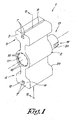
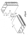
- Figures 1 and 2 represent an improved T-joint 1 according to the invention which is provided with a profiled body 2 which is made for example but not necessarily of aluminium and which, in this case, is provided with two wings 3 and 4 on its outside which are provided, on their respective far ends 5 and 6, with two ribs 7 bent towards each other on their far ends so as to form longitudinal grooves 8.
- a profiled body 2 which is made for example but not necessarily of aluminium and which, in this case, is provided with two wings 3 and 4 on its outside which are provided, on their respective far ends 5 and 6, with two ribs 7 bent towards each other on their far ends so as to form longitudinal grooves 8.
- a guide 9 in the form of a hole which extends through this body 2, in the axial direction X-X' of the profiled body 2.
- the above-mentioned guide 9 has a step-like course in the axial direction, in other words it has a first part 10 with a diameter D1 and a second part 11 with a diameter D2 which is smaller than the above-mentioned first diameter D1, such that at the transition between these parts 10 and 11 a stop 12 is formed.
- a pen 13 whose diameter is somewhat smaller than the above-mentioned diameter D2 and which is pushed along the first part 10 into the second part 11 of the guide 9 and which is provided with an outward directed collar 14 on one far end whose diameter is larger than the diameter D2 and which can be pushed up against the above-mentioned stop 12, such that, in this position, the pen 13 protrudes from the body 2 with a certain part having a length L on one far end of the guide 9.
- the pen 13 is maintained in its extreme rest position by means of a spring 15 which is provided in a recess 16 in the pen 13 with one far end and which is clamped by means of a cover plate 17 which covers the other far end of the guide 9 and which is fixed to the body 2.
- the cover plate 17 is fixed to the body 2 as the above-mentioned far end of the guide 9 is made with a somewhat larger diameter so as to form a shoulder on which the cover plate 17 rests and whereby the cover plate 17 is being kept in place by providing mechanical deformations 18 in the material of the body 2 round the cover plate 17.
- the above-mentioned pen 13 is provided with one or several, in this case two springy elements 20 at its crosscut free end 19 which, in this case, but not necessarily, are part of an accessory 21 provided on said crosscut far end 19, which accessory 21 is made in the shape of a strip 22, preferably of a resilient material, such as for example stainless steel, and whereby the above-mentioned springy elements 20 are formed of the free ends of the strip 22 which are bent slantingly towards the body 2, as if it were to form a sort of barbs.
- the above-mentioned springy elements 20 can also be made in the form of separate elements provided on the free ends of the above-mentioned strip 22.
- the above-mentioned strip 22 is in this case provided on the crosscut far end 19 of the above-mentioned pen 13 by means of a mechanical deformation of the material of this pen 13, but it is clear that it can be fixed in many other ways, such as for example by means of a wringing fit, gluing, screwing, snapping in, a locking pin or the like.
- T-joint 1 The use of an improved T-joint 1 according to the invention is represented in figures 5 to 7 and it is very simple and as follows.
- the T-joint 1 is hereby, with its pen 13 directed outward, pushed entirely in the strut 23 until the end face 26 coincides with the far end of the strut 23.
- the T-joint 1 is subsequently locked in the strut 23 in the axial direction, for example by means of glue, screws or the like, not represented in the figures.
- the pen 13 In order to subsequently provide for a connection between the struts 23 and 24, the pen 13 must be pushed in the guide 9 of the body 2 by exerting a force in the opposite sense of the force exerted on the pen 13 by the above-mentioned spring 16.
- the strut 23 can be pushed between two struts 24 until the pen 13, under the influence of the resilience, dashes into an opening 27 in the second strut 24.
- an improved T-joint according to the invention can be assembled and mounted in a fast and simple manner, since the orientation of the pen 13 in relation to the body 2 does not matter.
- Figures 8 to 10 represent a possible variant of an improved T-joint 1 according to the invention whereby the body 2, and in particular the wing 3, is made in two parts, with a first part 29 which is fixed in the strut 23 and a second part 30 which can move in relation to the above-mentioned first part 29 respectively.
- clamping means in the form of a conical threaded hole in which has been provided an adjusting screw 31 with a countersunk head 32.
- the respective wings 3 and 4 are not provided with ribs 7 bent towards each other.
- the other wing 4 is made as an L-shaped profiled part 33 which, as represented in figure 10, is held between a rib 34 in the strut 23 and a wall 35 of this strut 23 when mounted.
- wing 3 rests against a second rib 5 in the strut 23, whereas the mobile part 30 is provided against the above-mentioned wall 35 of this strut 23.
- the adjusting screw 31 is tightened, such that the part 30 is pushed away from the part 29 and the body 2 is clamped between the rib 36 and the wall 35.
- the pen 13 is provided with a shank 37 and protrudes from the body 2 with the springy elements 20 on one far end, whereas the shank 37 protrudes from the other far end.
- the above-mentioned shank 37 is provided with locking means 38 which prevent an axial movement in one direction and which in particular form a stop to the axial movement of the pen 13 under the influence of the spring 15.
- the above-mentioned locking means 38 are formed of a locking ring 39 provided in a circumferential groove 40 in the above-mentioned rear end of the pen 13.
- the locking means 38 can be adjusted, for example since one or several circumferential grooves 41 are provided, such that the above-mentioned locking ring 39 can also be provided in other grooves, depending on whether a sealing is either or not used between the struts 23 and 24.
- figures 11 and 12 represent another embodiment of an improved T-joint 1 according to the invention, whereby the above-mentioned accessory 21 is made in the shape of a ring 42 of a resilient material, such as for example stainless steel, which in this case has two springy wings 43 as springy elements and which, as represented in greater detail in figures 13 and 14, is pushed over a protrusion 44 on the crosscut far end of the pen 13 and which is locked by the mechanical deformation of said protrusion 44 after the accessory 21 has been provided.
- a resilient material such as for example stainless steel
- accessory 21 can be made in all sorts of materials which preferably but not necessarily have some resilience, such as for example plastic, spring steel or the like.
- the above-mentioned springy elements can be made in one piece with the above-mentioned accessory 21 or with the pen 13, or they can be made as separate thereof.
Landscapes
- Engineering & Computer Science (AREA)
- Architecture (AREA)
- Civil Engineering (AREA)
- Structural Engineering (AREA)
- Physics & Mathematics (AREA)
- Electromagnetism (AREA)
- Mechanical Pencils And Projecting And Retracting Systems Therefor, And Multi-System Writing Instruments (AREA)
- Mutual Connection Of Rods And Tubes (AREA)
- Coupling Device And Connection With Printed Circuit (AREA)
- Exchange Systems With Centralized Control (AREA)
- Mechanical Coupling Of Light Guides (AREA)
- Snaps, Bayonet Connections, Set Pins, And Snap Rings (AREA)
Applications Claiming Priority (1)
| Application Number | Priority Date | Filing Date | Title |
|---|---|---|---|
| BE2005/0599A BE1016889A3 (nl) | 2005-12-12 | 2005-12-12 | Verbeterde t-verbinder. |
Publications (3)
| Publication Number | Publication Date |
|---|---|
| EP1795665A2 true EP1795665A2 (de) | 2007-06-13 |
| EP1795665A3 EP1795665A3 (de) | 2010-01-13 |
| EP1795665B1 EP1795665B1 (de) | 2010-09-08 |
Family
ID=36424603
Family Applications (1)
| Application Number | Title | Priority Date | Filing Date |
|---|---|---|---|
| EP06025430A Not-in-force EP1795665B1 (de) | 2005-12-12 | 2006-12-08 | T-Verbindung |
Country Status (4)
| Country | Link |
|---|---|
| EP (1) | EP1795665B1 (de) |
| AT (1) | ATE480678T1 (de) |
| BE (1) | BE1016889A3 (de) |
| DE (1) | DE602006016715D1 (de) |
Cited By (5)
| Publication number | Priority date | Publication date | Assignee | Title |
|---|---|---|---|---|
| DE102009008380A1 (de) * | 2009-02-11 | 2010-08-12 | SCHÜCO International KG | T-Verbindung |
| ITMI20110658A1 (it) * | 2011-04-18 | 2012-10-19 | Ponzio Sud S R L | Dispositivo di bloccaggio di un traverso ad un montante di una facciata continua |
| EP3470593A1 (de) | 2017-10-16 | 2019-04-17 | Sapa Building Systems Sp. z o.o. | T-verbinder zum verbinden von profilen und einem profil zur aufnahme des t-verbinders |
| CN112177215A (zh) * | 2020-04-17 | 2021-01-05 | 杭州斯泰新材料技术有限公司 | 可滑动式横梁固定件 |
| CN115059222A (zh) * | 2022-06-23 | 2022-09-16 | 索亿斯(厦门)科技有限公司 | 一种立体光伏支架结构 |
Families Citing this family (1)
| Publication number | Priority date | Publication date | Assignee | Title |
|---|---|---|---|---|
| DE102020103627B4 (de) | 2019-02-14 | 2023-10-12 | HUECK System GmbH & Co. KG | Federstiftstossverbinder |
Family Cites Families (4)
| Publication number | Priority date | Publication date | Assignee | Title |
|---|---|---|---|---|
| DE3419294A1 (de) * | 1984-05-24 | 1985-11-28 | SCHÜCO Heinz Schürmann GmbH & Co, 4800 Bielefeld | T-verbinder fuer einen sprossenstoss in einer vorsatzfassade |
| DE3809951A1 (de) * | 1988-03-24 | 1989-10-05 | Schueco Int Gmbh & Co | T-verbindung zwischen zwei profilen, vorzugsweise einem sprossen- und einem pfostenprofil einer fassade |
| DE19901775A1 (de) * | 1999-01-18 | 2000-07-20 | Schueco Int Kg | T-Verbindung zwischen einem Sprossen- und einem Pfostenprofil einer Fassade oder eines Lichtdaches |
| DE29910027U1 (de) * | 1999-06-09 | 1999-07-29 | Götz GmbH, 71636 Ludwigsburg | Pfosten-Riegel-System für mit Ausfachungen versehene Gebäudefassaden |
-
2005
- 2005-12-12 BE BE2005/0599A patent/BE1016889A3/nl not_active IP Right Cessation
-
2006
- 2006-12-08 EP EP06025430A patent/EP1795665B1/de not_active Not-in-force
- 2006-12-08 AT AT06025430T patent/ATE480678T1/de not_active IP Right Cessation
- 2006-12-08 DE DE602006016715T patent/DE602006016715D1/de active Active
Cited By (6)
| Publication number | Priority date | Publication date | Assignee | Title |
|---|---|---|---|---|
| DE102009008380A1 (de) * | 2009-02-11 | 2010-08-12 | SCHÜCO International KG | T-Verbindung |
| ITMI20110658A1 (it) * | 2011-04-18 | 2012-10-19 | Ponzio Sud S R L | Dispositivo di bloccaggio di un traverso ad un montante di una facciata continua |
| EP3470593A1 (de) | 2017-10-16 | 2019-04-17 | Sapa Building Systems Sp. z o.o. | T-verbinder zum verbinden von profilen und einem profil zur aufnahme des t-verbinders |
| CN112177215A (zh) * | 2020-04-17 | 2021-01-05 | 杭州斯泰新材料技术有限公司 | 可滑动式横梁固定件 |
| CN112177215B (zh) * | 2020-04-17 | 2022-08-23 | 杭州斯泰新材料技术有限公司 | 可滑动式横梁固定件 |
| CN115059222A (zh) * | 2022-06-23 | 2022-09-16 | 索亿斯(厦门)科技有限公司 | 一种立体光伏支架结构 |
Also Published As
| Publication number | Publication date |
|---|---|
| BE1016889A3 (nl) | 2007-09-04 |
| ATE480678T1 (de) | 2010-09-15 |
| EP1795665B1 (de) | 2010-09-08 |
| DE602006016715D1 (de) | 2010-10-21 |
| EP1795665A3 (de) | 2010-01-13 |
Similar Documents
| Publication | Publication Date | Title |
|---|---|---|
| US11898590B2 (en) | Expandable collet bodies with sectional finger-based anti-rotation feature, clips, inserts and systems thereof | |
| US6250865B1 (en) | Screw tipped anchor assembly | |
| ES2700464T3 (es) | Abrazadera para tubo | |
| US6960045B2 (en) | Connector for profiles | |
| CA2483173C (en) | Pipe joint | |
| CA2502008A1 (en) | Anchor with toggle for hollow walls | |
| SK111699A3 (en) | Screwing element | |
| KR900006086A (ko) | 푸쉬-인 패스너 | |
| US6685384B2 (en) | Cable harness assembly for bicycle | |
| EP1795665B1 (de) | T-Verbindung | |
| US6874200B2 (en) | Hinge and hinge part therefor | |
| AU2010202263A1 (en) | Toggle bolt type fastener assembly for mounting articles upon a panel member | |
| DE202017104065U1 (de) | Montagevorrichtung | |
| EP1840441A2 (de) | Schlauchanschlusselement | |
| US6820789B2 (en) | Magazine with bolt-shaped fastening elements for a setting tool | |
| US7101108B1 (en) | Collar for taking hold of fixation piece of window shade rod | |
| WO2016120097A1 (de) | Scankörpersystem zur bestimmung einer positionierung und ausrichtung eines dentalimplantats | |
| WO2002038317A1 (en) | Key for mounting and dismounting of a cutting insert | |
| JP6267076B2 (ja) | スライド式ボルト及びそれを用いた室外機用の据付台 | |
| CA2772039C (en) | Screw tipped anchor assembly | |
| US20030056331A1 (en) | Method and apparatus for providing a door hinge with integral doorstop | |
| EP3059461B1 (de) | Markisenarm mit einem markisenarmgelenk, das zwei durch ein verbindungselement verbundene abdeckkappen aufweist | |
| CH708905B1 (de) | Rahmensystem für ein Partikelschutzgitter. | |
| DE4009752A1 (de) | Drehriegelverschluss mit einstellbarem abstand zwischen drehriegel und gehaeuse | |
| CN210827725U (zh) | 一种伸缩防臭下水管结构 |
Legal Events
| Date | Code | Title | Description |
|---|---|---|---|
| PUAI | Public reference made under article 153(3) epc to a published international application that has entered the european phase |
Free format text: ORIGINAL CODE: 0009012 |
|
| AK | Designated contracting states |
Kind code of ref document: A2 Designated state(s): AT BE BG CH CY CZ DE DK EE ES FI FR GB GR HU IE IS IT LI LT LU LV MC NL PL PT RO SE SI SK TR |
|
| AX | Request for extension of the european patent |
Extension state: AL BA HR MK YU |
|
| PUAL | Search report despatched |
Free format text: ORIGINAL CODE: 0009013 |
|
| AK | Designated contracting states |
Kind code of ref document: A3 Designated state(s): AT BE BG CH CY CZ DE DK EE ES FI FR GB GR HU IE IS IT LI LT LU LV MC NL PL PT RO SE SI SK TR |
|
| AX | Request for extension of the european patent |
Extension state: AL BA HR MK RS |
|
| 17P | Request for examination filed |
Effective date: 20100202 |
|
| GRAP | Despatch of communication of intention to grant a patent |
Free format text: ORIGINAL CODE: EPIDOSNIGR1 |
|
| RIC1 | Information provided on ipc code assigned before grant |
Ipc: E04B 2/96 20060101AFI20100318BHEP Ipc: E04D 3/08 20060101ALI20100318BHEP |
|
| GRAS | Grant fee paid |
Free format text: ORIGINAL CODE: EPIDOSNIGR3 |
|
| GRAA | (expected) grant |
Free format text: ORIGINAL CODE: 0009210 |
|
| AK | Designated contracting states |
Kind code of ref document: B1 Designated state(s): AT BE BG CH CY CZ DE DK EE ES FI FR GB GR HU IE IS IT LI LT LU LV MC NL PL PT RO SE SI SK TR |
|
| REG | Reference to a national code |
Ref country code: GB Ref legal event code: FG4D |
|
| AKX | Designation fees paid |
Designated state(s): AT BE BG CH CY CZ DE DK EE ES FI FR GB GR HU IE IS IT LI LT LU LV MC NL PL PT RO SE SI SK TR |
|
| REG | Reference to a national code |
Ref country code: CH Ref legal event code: EP |
|
| REG | Reference to a national code |
Ref country code: IE Ref legal event code: FG4D |
|
| REF | Corresponds to: |
Ref document number: 602006016715 Country of ref document: DE Date of ref document: 20101021 Kind code of ref document: P |
|
| REG | Reference to a national code |
Ref country code: NL Ref legal event code: VDEP Effective date: 20100908 |
|
| PG25 | Lapsed in a contracting state [announced via postgrant information from national office to epo] |
Ref country code: LT Free format text: LAPSE BECAUSE OF FAILURE TO SUBMIT A TRANSLATION OF THE DESCRIPTION OR TO PAY THE FEE WITHIN THE PRESCRIBED TIME-LIMIT Effective date: 20100908 Ref country code: AT Free format text: LAPSE BECAUSE OF FAILURE TO SUBMIT A TRANSLATION OF THE DESCRIPTION OR TO PAY THE FEE WITHIN THE PRESCRIBED TIME-LIMIT Effective date: 20100908 Ref country code: FI Free format text: LAPSE BECAUSE OF FAILURE TO SUBMIT A TRANSLATION OF THE DESCRIPTION OR TO PAY THE FEE WITHIN THE PRESCRIBED TIME-LIMIT Effective date: 20100908 |
|
| LTIE | Lt: invalidation of european patent or patent extension |
Effective date: 20100908 |
|
| PG25 | Lapsed in a contracting state [announced via postgrant information from national office to epo] |
Ref country code: SI Free format text: LAPSE BECAUSE OF FAILURE TO SUBMIT A TRANSLATION OF THE DESCRIPTION OR TO PAY THE FEE WITHIN THE PRESCRIBED TIME-LIMIT Effective date: 20100908 Ref country code: PL Free format text: LAPSE BECAUSE OF FAILURE TO SUBMIT A TRANSLATION OF THE DESCRIPTION OR TO PAY THE FEE WITHIN THE PRESCRIBED TIME-LIMIT Effective date: 20100908 Ref country code: CY Free format text: LAPSE BECAUSE OF FAILURE TO SUBMIT A TRANSLATION OF THE DESCRIPTION OR TO PAY THE FEE WITHIN THE PRESCRIBED TIME-LIMIT Effective date: 20100908 |
|
| PG25 | Lapsed in a contracting state [announced via postgrant information from national office to epo] |
Ref country code: LV Free format text: LAPSE BECAUSE OF FAILURE TO SUBMIT A TRANSLATION OF THE DESCRIPTION OR TO PAY THE FEE WITHIN THE PRESCRIBED TIME-LIMIT Effective date: 20100908 Ref country code: NL Free format text: LAPSE BECAUSE OF FAILURE TO SUBMIT A TRANSLATION OF THE DESCRIPTION OR TO PAY THE FEE WITHIN THE PRESCRIBED TIME-LIMIT Effective date: 20100908 Ref country code: SE Free format text: LAPSE BECAUSE OF FAILURE TO SUBMIT A TRANSLATION OF THE DESCRIPTION OR TO PAY THE FEE WITHIN THE PRESCRIBED TIME-LIMIT Effective date: 20100908 Ref country code: GR Free format text: LAPSE BECAUSE OF FAILURE TO SUBMIT A TRANSLATION OF THE DESCRIPTION OR TO PAY THE FEE WITHIN THE PRESCRIBED TIME-LIMIT Effective date: 20101209 |
|
| PG25 | Lapsed in a contracting state [announced via postgrant information from national office to epo] |
Ref country code: PT Free format text: LAPSE BECAUSE OF FAILURE TO SUBMIT A TRANSLATION OF THE DESCRIPTION OR TO PAY THE FEE WITHIN THE PRESCRIBED TIME-LIMIT Effective date: 20110110 Ref country code: CZ Free format text: LAPSE BECAUSE OF FAILURE TO SUBMIT A TRANSLATION OF THE DESCRIPTION OR TO PAY THE FEE WITHIN THE PRESCRIBED TIME-LIMIT Effective date: 20100908 Ref country code: RO Free format text: LAPSE BECAUSE OF FAILURE TO SUBMIT A TRANSLATION OF THE DESCRIPTION OR TO PAY THE FEE WITHIN THE PRESCRIBED TIME-LIMIT Effective date: 20100908 Ref country code: SK Free format text: LAPSE BECAUSE OF FAILURE TO SUBMIT A TRANSLATION OF THE DESCRIPTION OR TO PAY THE FEE WITHIN THE PRESCRIBED TIME-LIMIT Effective date: 20100908 Ref country code: EE Free format text: LAPSE BECAUSE OF FAILURE TO SUBMIT A TRANSLATION OF THE DESCRIPTION OR TO PAY THE FEE WITHIN THE PRESCRIBED TIME-LIMIT Effective date: 20100908 Ref country code: IS Free format text: LAPSE BECAUSE OF FAILURE TO SUBMIT A TRANSLATION OF THE DESCRIPTION OR TO PAY THE FEE WITHIN THE PRESCRIBED TIME-LIMIT Effective date: 20110108 Ref country code: IT Free format text: LAPSE BECAUSE OF FAILURE TO SUBMIT A TRANSLATION OF THE DESCRIPTION OR TO PAY THE FEE WITHIN THE PRESCRIBED TIME-LIMIT Effective date: 20100908 |
|
| PG25 | Lapsed in a contracting state [announced via postgrant information from national office to epo] |
Ref country code: BE Free format text: LAPSE BECAUSE OF FAILURE TO SUBMIT A TRANSLATION OF THE DESCRIPTION OR TO PAY THE FEE WITHIN THE PRESCRIBED TIME-LIMIT Effective date: 20100908 Ref country code: ES Free format text: LAPSE BECAUSE OF FAILURE TO SUBMIT A TRANSLATION OF THE DESCRIPTION OR TO PAY THE FEE WITHIN THE PRESCRIBED TIME-LIMIT Effective date: 20101219 |
|
| PLBE | No opposition filed within time limit |
Free format text: ORIGINAL CODE: 0009261 |
|
| STAA | Information on the status of an ep patent application or granted ep patent |
Free format text: STATUS: NO OPPOSITION FILED WITHIN TIME LIMIT |
|
| PG25 | Lapsed in a contracting state [announced via postgrant information from national office to epo] |
Ref country code: MC Free format text: LAPSE BECAUSE OF NON-PAYMENT OF DUE FEES Effective date: 20101231 |
|
| REG | Reference to a national code |
Ref country code: CH Ref legal event code: PL |
|
| 26N | No opposition filed |
Effective date: 20110609 |
|
| GBPC | Gb: european patent ceased through non-payment of renewal fee |
Effective date: 20101208 |
|
| PG25 | Lapsed in a contracting state [announced via postgrant information from national office to epo] |
Ref country code: DK Free format text: LAPSE BECAUSE OF FAILURE TO SUBMIT A TRANSLATION OF THE DESCRIPTION OR TO PAY THE FEE WITHIN THE PRESCRIBED TIME-LIMIT Effective date: 20100908 |
|
| REG | Reference to a national code |
Ref country code: FR Ref legal event code: ST Effective date: 20110831 |
|
| REG | Reference to a national code |
Ref country code: DE Ref legal event code: R097 Ref document number: 602006016715 Country of ref document: DE Effective date: 20110609 |
|
| PG25 | Lapsed in a contracting state [announced via postgrant information from national office to epo] |
Ref country code: FR Free format text: LAPSE BECAUSE OF NON-PAYMENT OF DUE FEES Effective date: 20110103 Ref country code: IE Free format text: LAPSE BECAUSE OF NON-PAYMENT OF DUE FEES Effective date: 20101208 Ref country code: CH Free format text: LAPSE BECAUSE OF NON-PAYMENT OF DUE FEES Effective date: 20101231 Ref country code: LI Free format text: LAPSE BECAUSE OF NON-PAYMENT OF DUE FEES Effective date: 20101231 |
|
| PG25 | Lapsed in a contracting state [announced via postgrant information from national office to epo] |
Ref country code: GB Free format text: LAPSE BECAUSE OF NON-PAYMENT OF DUE FEES Effective date: 20101208 |
|
| PG25 | Lapsed in a contracting state [announced via postgrant information from national office to epo] |
Ref country code: BG Free format text: LAPSE BECAUSE OF FAILURE TO SUBMIT A TRANSLATION OF THE DESCRIPTION OR TO PAY THE FEE WITHIN THE PRESCRIBED TIME-LIMIT Effective date: 20100908 Ref country code: HU Free format text: LAPSE BECAUSE OF FAILURE TO SUBMIT A TRANSLATION OF THE DESCRIPTION OR TO PAY THE FEE WITHIN THE PRESCRIBED TIME-LIMIT Effective date: 20110309 Ref country code: LU Free format text: LAPSE BECAUSE OF NON-PAYMENT OF DUE FEES Effective date: 20101208 |
|
| PG25 | Lapsed in a contracting state [announced via postgrant information from national office to epo] |
Ref country code: TR Free format text: LAPSE BECAUSE OF FAILURE TO SUBMIT A TRANSLATION OF THE DESCRIPTION OR TO PAY THE FEE WITHIN THE PRESCRIBED TIME-LIMIT Effective date: 20100908 |
|
| PG25 | Lapsed in a contracting state [announced via postgrant information from national office to epo] |
Ref country code: BG Free format text: LAPSE BECAUSE OF FAILURE TO SUBMIT A TRANSLATION OF THE DESCRIPTION OR TO PAY THE FEE WITHIN THE PRESCRIBED TIME-LIMIT Effective date: 20101208 |
|
| P01 | Opt-out of the competence of the unified patent court (upc) registered |
Effective date: 20230418 |
|
| PGFP | Annual fee paid to national office [announced via postgrant information from national office to epo] |
Ref country code: DE Payment date: 20230929 Year of fee payment: 18 |
|
| REG | Reference to a national code |
Ref country code: DE Ref legal event code: R119 Ref document number: 602006016715 Country of ref document: DE |
|
| PG25 | Lapsed in a contracting state [announced via postgrant information from national office to epo] |
Ref country code: DE Free format text: LAPSE BECAUSE OF NON-PAYMENT OF DUE FEES Effective date: 20250701 |