EP1795802B1 - Contrôle indépendant du carburant pilote dans une buse secondaire d'injection - Google Patents
Contrôle indépendant du carburant pilote dans une buse secondaire d'injection Download PDFInfo
- Publication number
- EP1795802B1 EP1795802B1 EP06125875.2A EP06125875A EP1795802B1 EP 1795802 B1 EP1795802 B1 EP 1795802B1 EP 06125875 A EP06125875 A EP 06125875A EP 1795802 B1 EP1795802 B1 EP 1795802B1
- Authority
- EP
- European Patent Office
- Prior art keywords
- fuel
- secondary nozzle
- fuel flow
- combustor
- combustion chamber
- Prior art date
- Legal status (The legal status is an assumption and is not a legal conclusion. Google has not performed a legal analysis and makes no representation as to the accuracy of the status listed.)
- Active
Links
Images



Classifications
-
- F—MECHANICAL ENGINEERING; LIGHTING; HEATING; WEAPONS; BLASTING
- F23—COMBUSTION APPARATUS; COMBUSTION PROCESSES
- F23C—METHODS OR APPARATUS FOR COMBUSTION USING FLUID FUEL OR SOLID FUEL SUSPENDED IN A CARRIER GAS OR AIR
- F23C6/00—Combustion apparatus characterised by the combination of two or more combustion chambers or combustion zones, e.g. for staged combustion
- F23C6/04—Combustion apparatus characterised by the combination of two or more combustion chambers or combustion zones, e.g. for staged combustion in series connection
- F23C6/045—Combustion apparatus characterised by the combination of two or more combustion chambers or combustion zones, e.g. for staged combustion in series connection with staged combustion in a single enclosure
- F23C6/047—Combustion apparatus characterised by the combination of two or more combustion chambers or combustion zones, e.g. for staged combustion in series connection with staged combustion in a single enclosure with fuel supply in stages
-
- F—MECHANICAL ENGINEERING; LIGHTING; HEATING; WEAPONS; BLASTING
- F23—COMBUSTION APPARATUS; COMBUSTION PROCESSES
- F23L—SUPPLYING AIR OR NON-COMBUSTIBLE LIQUIDS OR GASES TO COMBUSTION APPARATUS IN GENERAL ; VALVES OR DAMPERS SPECIALLY ADAPTED FOR CONTROLLING AIR SUPPLY OR DRAUGHT IN COMBUSTION APPARATUS; INDUCING DRAUGHT IN COMBUSTION APPARATUS; TOPS FOR CHIMNEYS OR VENTILATING SHAFTS; TERMINALS FOR FLUES
- F23L7/00—Supplying non-combustible liquids or gases, other than air, to the fire, e.g. oxygen, steam
- F23L7/002—Supplying water
-
- F—MECHANICAL ENGINEERING; LIGHTING; HEATING; WEAPONS; BLASTING
- F23—COMBUSTION APPARATUS; COMBUSTION PROCESSES
- F23R—GENERATING COMBUSTION PRODUCTS OF HIGH PRESSURE OR HIGH VELOCITY, e.g. GAS-TURBINE COMBUSTION CHAMBERS
- F23R3/00—Continuous combustion chambers using liquid or gaseous fuel
- F23R3/28—Continuous combustion chambers using liquid or gaseous fuel characterised by the fuel supply
- F23R3/34—Feeding into different combustion zones
- F23R3/346—Feeding into different combustion zones for staged combustion
-
- F—MECHANICAL ENGINEERING; LIGHTING; HEATING; WEAPONS; BLASTING
- F23—COMBUSTION APPARATUS; COMBUSTION PROCESSES
- F23D—BURNERS
- F23D2209/00—Safety arrangements
- F23D2209/30—Purging
-
- F—MECHANICAL ENGINEERING; LIGHTING; HEATING; WEAPONS; BLASTING
- F23—COMBUSTION APPARATUS; COMBUSTION PROCESSES
- F23D—BURNERS
- F23D2900/00—Special features of, or arrangements for burners using fluid fuels or solid fuels suspended in a carrier gas
- F23D2900/00008—Burner assemblies with diffusion and premix modes, i.e. dual mode burners
-
- F—MECHANICAL ENGINEERING; LIGHTING; HEATING; WEAPONS; BLASTING
- F23—COMBUSTION APPARATUS; COMBUSTION PROCESSES
- F23D—BURNERS
- F23D2900/00—Special features of, or arrangements for burners using fluid fuels or solid fuels suspended in a carrier gas
- F23D2900/00015—Pilot burners specially adapted for low load or transient conditions, e.g. for increasing stability
-
- F—MECHANICAL ENGINEERING; LIGHTING; HEATING; WEAPONS; BLASTING
- F23—COMBUSTION APPARATUS; COMBUSTION PROCESSES
- F23D—BURNERS
- F23D2900/00—Special features of, or arrangements for burners using fluid fuels or solid fuels suspended in a carrier gas
- F23D2900/14—Special features of gas burners
- F23D2900/14004—Special features of gas burners with radially extending gas distribution spokes
Definitions
- This application relates generally to gas turbines, and more specifically, to a gas turbine combustor and a method for a gas turbine combustor with individually controlled fuel circuits intended to provide optimum combustion system emissions concentrations.
- a gas turbine combustor is essentially a device used for mixing fuel and air, and burning the resulting mixture.
- Gas turbine compressors pressurize inlet air which is then turned in direction or reverse flowed to the combustor where it is used to cool the combustor and also to provide air to the combustion process.
- Multiple combustion chamber assemblies may be utilized to achieve reliable and efficient turbine operation.
- Each combustion chamber assembly comprises a cylindrical combustor liner, a fuel injection system, and a transition piece that guides the flow of the hot gas from the combustor liner to the inlet of the turbine section.
- Gas turbines for which the present fuel nozzle design is to be utilized may include one combustor or several combustors arranged in a circular array about the turbine rotor axis.
- Document US6691516 B2 discloses a gas turbine combustor with a secondary combustion chamber and a fully premixed secondary fuel nozzle.
- the ability to control the amount of fuel flow to different regions of the combustor allows for the minimizing of CO and NOx emissions for a given set of operating conditions.
- the gas turbine combustor includes a primary combustion chamber, a plurality of primary nozzles, a secondary combustion chamber, and a secondary nozzle.
- the plurality of primary nozzles are capable of delivering fuel to the primary combustion chamber.
- the secondary combustion chamber is downstream of the primary combustion chamber.
- the secondary nozzle is capable of delivering fuel to the secondary combustion chamber.
- the secondary nozzle has a plurality of individually controlled fuel circuits.
- a method for controlling fuel flow in a secondary fuel nozzle for a gas turbine combustor is conveyed to a reaction zone of the combustor. And a second fuel flow is conveyed to a downstream combustion chamber of the combustor such that the first fuel flow is controlled independently of the second fuel flow and the second fuel flow is controlled independently of the first fuel flow.
- a gas turbine 10 (partially shown) includes a compressor 12 (also partially shown), a plurality of combustors 14 (one shown), and a turbine section represented here by a single blade 16. Although not specifically shown, the turbine is drivingly connected to the compressor 12 along a common axis.
- the compressor 12 pressurizes inlet air which is then reverse flowed to the combustor 14 where it is used to cool the combustor and to provide air to the combustion process.
- the plurality of combustors 14 are located in an annular array about the axis of the gas turbine.
- a transition duct 18 connects the outlet end of each combustor 14 with the inlet end of the turbine to deliver the hot products of combustion to the turbine in the form of an approved temperature profile.
- Each combustor 14 may comprise a primary or upstream combustion chamber 24 and a secondary or downstream combustion chamber 26 separated by a venturi throat region 28.
- the combustor 14 is surrounded by combustor flow sleeve 30 which channels compressor discharge air flow to the combustor 14.
- the combustor 14 is further surrounded by an outer casing 32 which is bolted to a turbine casing 34.
- Primary nozzles 36 provide fuel delivery to the upstream combustor 24 and are arranged in an annular array around a central secondary nozzle 38. Ignition is achieved in the various combustors 14 by means of sparkplug 20 in conjunction with crossfire tubes 22 (one shown).
- the secondary nozzle 38 provides fuel delivery to the downstream combustion chamber 26.
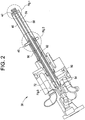
- Figure 2 illustrates an exemplary secondary nozzle 38 having two fuel introduction locations including secondary nozzle pegs 40 and a secondary nozzle pilot tip 42.
- the secondary nozzle pegs 40 provide fuel to a pre-mix reaction zone of the combustor 14, while the secondary nozzle pilot tip 42 provides fuel to the downstream combustion chamber 26 where it is immediately burned (diffusion combustion).
- the secondary nozzle 38 is a combustion system fuel delivery device having separate and individually controlled fuel circuits which allows for the ability to individually vary fuel flow rates delivered to the two fuel introduction locations (secondary nozzle pegs 40 and secondary nozzle pilot tip 42).
- the fuel flow rate through the secondary nozzle pilot tip 42 may be varied independently from the fuel flow rate through the secondary nozzle pegs 40 and the fuel flow rate through the secondary nozzle pegs 40 may be varied independently from the fuel flow rate through the secondary nozzle pilot tip 42.
- the secondary nozzle pegs 40 and the secondary nozzle pilot tip 42 each have their own independent fuel piping circuit, with each having independent and exclusive fuel sources.
- the fuel flow rate delivered to the secondary nozzle pilot tip 42 is less than about 2% of the total gas turbine fuel flow and is capable of, in one embodiment, delivering and controlling the fuel flow rate in the range of about 0.002 pps (pounds per second) to about 0.020 pps.
- Independent control of the two fuel introduction locations provides an additional degree of freedom which may be exercised to optimize the combustion system and minimize the CO and NOx emissions produced by the gas turbine system.
- the independent control of the two fuel introduction locations may achieve sub-5ppm (parts per million) NOx emissions across the full ambient and load range.
- the fuel piping circuits and passages are described in greater detail below.
- FIG. 3 further illustrates the secondary nozzle pegs 40 and the independent fuel circuits and passages.
- the secondary fuel nozzle 38 comprises a series of concentric tubes.
- the two radially outermost concentric tubes 44 and 48 provide a tertiary gas passage 46.
- the tertiary gas passage 46 provides tertiary gas to the secondary nozzle pilot tip 42.
- a secondary gas fuel passage 50 adjacent to the tertiary gas passage 46, is formed between concentric tubes 48 and 52.
- the secondary gas fuel passage 50 communicates with the plurality of radially extending secondary nozzle pegs 40 arranged about the circumference of the secondary nozzle 38 and supplies secondary gas fuel to the secondary nozzle pegs 40.
- a sub-pilot gas fuel passage 54 adjacent to the secondary gas fuel passage 50, is defined between concentric tubes 52 and 56.
- the sub-pilot gas fuel passage 54 supplies sub-pilot gas fuel to the secondary nozzle pilot tip 42.
- a water purge passage 58 adjacent to the sub-pilot gas fuel passage 54, is defined between concentric tubes 56 and 60.
- the water purge passage 58 provides water to the secondary nozzle pilot tip 42 to effect carbon monoxide (CO) and nitrogen oxide (NOx) emission reductions.
- a liquid fuel passage 62 the innermost of the series of concentric passages forming the secondary nozzle 38, is defined by tube 60.
- the liquid fuel passage 62 provides liquid fuel to the secondary nozzle pilot tip 42.
- Figure 2 shows four independent fuel circuits, it should be noted that the number of fuel circuits may be varied according to operational and design considerations.
- FIG. 4 further illustrates the secondary nozzle pilot tip 42.
- the secondary nozzle pilot tip 42 may be a three piece assembly having a sub-pilot portion 64, which contains the sub-pilot gas fuel at the secondary nozzle pilot tip 42 and abuts tube 52, a water purge portion 66, which contains the water at the secondary nozzle pilot tip 42 and abuts tube 56, and a tip portion 68, which forms an outlet end to the secondary nozzle 38.
- the three piece secondary nozzle pilot tip may be fixedly joined, for example, by an electron beam welding process.
- Figure 5 illustrates a lip seal 70 between tube 56 and a secondary nozzle base 72.
- the lip seal 70 prevents fuel leakage within the secondary nozzle 38 by forming a controlled interference fit between the tube 56 and the secondary nozzle base. It will be appreciated that lip seals 70 may be utilized between other fuel passage defining tubes (other than tube 56) and the secondary nozzle base 72 as required to prevent fuel leakage.
Landscapes
- Engineering & Computer Science (AREA)
- Chemical & Material Sciences (AREA)
- Combustion & Propulsion (AREA)
- Mechanical Engineering (AREA)
- General Engineering & Computer Science (AREA)
- Fuel-Injection Apparatus (AREA)
Claims (4)
- Chambre de combustion de turbine à gaz (14) comprenant :un espace de combustion primaire (24) ;une pluralité de buses primaires (36) capable de distribuer un carburant à l'espace de combustion primaire (24) ;un espace de combustion secondaire (26) en aval de l'espace de combustion primaire (24) ; et,une buse secondaire (38) capable de distribuer un carburant à l'espace de combustion secondaire (26) ; caractérisée en ce quela buse secondaire (38) ayant une pluralité de circuits de carburant commandés individuellement ; dans laquelle un ou plusieurs des circuits de carburant commandés individuellement sont en communication avec un ergot de buse secondaire (40) et un ou plusieurs des circuits de carburant commandés individuellement sont en communication avec une pointe pilote de buse secondaire (42) pour faire varier individuellement les débits de carburant distribués à l'ergot de buse secondaire (40) et à la pointe pilote de buse secondaire (42).
- Procédé de commande de flux de carburant dans une buse de carburant secondaire (38) d'une chambre de combustion de turbine à gaz (14) selon la revendication 1 comprenant : le transport d'un premier flux de carburant vers une zone de réaction de la chambre de combustion ; et, le transport d'un deuxième flux de carburant vers un espace de combustion aval (26) de la chambre de combustion (14) dans lequel le premier flux de carburant est commandé indépendamment du deuxième flux de carburant et le deuxième flux de carburant est commandé indépendamment du premier flux de carburant.
- Procédé selon la revendication 2, dans lequel le transport du deuxième flux de carburant est inférieur à environ 2 % du flux de carburant total de turbine à gaz.
- Procédé selon la revendication 2, dans lequel le transport du deuxième flux de carburant est dans la plage de 0,91 g/s à 9,1 g/s.
Applications Claiming Priority (1)
| Application Number | Priority Date | Filing Date | Title |
|---|---|---|---|
| US11/301,794 US7854121B2 (en) | 2005-12-12 | 2005-12-12 | Independent pilot fuel control in secondary fuel nozzle |
Publications (3)
| Publication Number | Publication Date |
|---|---|
| EP1795802A2 EP1795802A2 (fr) | 2007-06-13 |
| EP1795802A3 EP1795802A3 (fr) | 2015-07-15 |
| EP1795802B1 true EP1795802B1 (fr) | 2020-10-07 |
Family
ID=37805920
Family Applications (1)
| Application Number | Title | Priority Date | Filing Date |
|---|---|---|---|
| EP06125875.2A Active EP1795802B1 (fr) | 2005-12-12 | 2006-12-12 | Contrôle indépendant du carburant pilote dans une buse secondaire d'injection |
Country Status (4)
| Country | Link |
|---|---|
| US (1) | US7854121B2 (fr) |
| EP (1) | EP1795802B1 (fr) |
| JP (1) | JP5441304B2 (fr) |
| CN (1) | CN101008497B (fr) |
Families Citing this family (30)
| Publication number | Priority date | Publication date | Assignee | Title |
|---|---|---|---|---|
| US7574865B2 (en) * | 2004-11-18 | 2009-08-18 | Siemens Energy, Inc. | Combustor flow sleeve with optimized cooling and airflow distribution |
| US8028529B2 (en) * | 2006-05-04 | 2011-10-04 | General Electric Company | Low emissions gas turbine combustor |
| US8166763B2 (en) * | 2006-09-14 | 2012-05-01 | Solar Turbines Inc. | Gas turbine fuel injector with a removable pilot assembly |
| US8448441B2 (en) * | 2007-07-26 | 2013-05-28 | General Electric Company | Fuel nozzle assembly for a gas turbine engine |
| US8286433B2 (en) * | 2007-10-26 | 2012-10-16 | Solar Turbines Inc. | Gas turbine fuel injector with removable pilot liquid tube |
| US8028512B2 (en) | 2007-11-28 | 2011-10-04 | Solar Turbines Inc. | Active combustion control for a turbine engine |
| US7757491B2 (en) * | 2008-05-09 | 2010-07-20 | General Electric Company | Fuel nozzle for a gas turbine engine and method for fabricating the same |
| US20100058767A1 (en) * | 2008-09-05 | 2010-03-11 | General Electric Company | Swirl angle of secondary fuel nozzle for turbomachine combustor |
| US20100192582A1 (en) | 2009-02-04 | 2010-08-05 | Robert Bland | Combustor nozzle |
| US20100205970A1 (en) * | 2009-02-19 | 2010-08-19 | General Electric Company | Systems, Methods, and Apparatus Providing a Secondary Fuel Nozzle Assembly |
| US20110083440A1 (en) * | 2009-10-14 | 2011-04-14 | General Electric Company | High strength crossover manifold and method of joining |
| US20110089266A1 (en) * | 2009-10-16 | 2011-04-21 | General Electric Company | Fuel nozzle lip seals |
| US8662502B2 (en) * | 2009-10-16 | 2014-03-04 | General Electric Company | Fuel nozzle seal spacer and method of installing the same |
| US20110244410A1 (en) * | 2010-03-30 | 2011-10-06 | General Electric Company | Pilot system for combustors |
| US9010119B2 (en) * | 2010-11-03 | 2015-04-21 | General Electric Company | Premixing nozzle |
| US8661825B2 (en) * | 2010-12-17 | 2014-03-04 | General Electric Company | Pegless secondary fuel nozzle including a unitary fuel injection manifold |
| US9371989B2 (en) * | 2011-05-18 | 2016-06-21 | General Electric Company | Combustor nozzle and method for supplying fuel to a combustor |
| US9217570B2 (en) * | 2012-01-20 | 2015-12-22 | General Electric Company | Axial flow fuel nozzle with a stepped center body |
| JP5934432B2 (ja) * | 2012-04-27 | 2016-06-15 | ゼネラル・エレクトリック・カンパニイ | ガスタービンエンジンの燃料漏れを防止するためのシステムおよび方法 |
| US9435540B2 (en) | 2013-12-11 | 2016-09-06 | General Electric Company | Fuel injector with premix pilot nozzle |
| US9714767B2 (en) | 2014-11-26 | 2017-07-25 | General Electric Company | Premix fuel nozzle assembly |
| US10030869B2 (en) | 2014-11-26 | 2018-07-24 | General Electric Company | Premix fuel nozzle assembly |
| US11015809B2 (en) | 2014-12-30 | 2021-05-25 | General Electric Company | Pilot nozzle in gas turbine combustor |
| US9982892B2 (en) | 2015-04-16 | 2018-05-29 | General Electric Company | Fuel nozzle assembly including a pilot nozzle |
| US9803867B2 (en) | 2015-04-21 | 2017-10-31 | General Electric Company | Premix pilot nozzle |
| AU2016254323B2 (en) | 2015-04-30 | 2019-11-28 | Nuovo Pignone Tecnologie Srl | Ultra-low NOx emission gas turbine engine in mechanical drive applications |
| EP3412972B1 (fr) * | 2017-06-09 | 2020-10-07 | Ansaldo Energia Switzerland AG | Turbine à gaz comprenant une pluralité de chambres de combustion tubulaires |
| US11371706B2 (en) | 2017-12-18 | 2022-06-28 | General Electric Company | Premixed pilot nozzle for gas turbine combustor |
| CN114576015B (zh) * | 2022-02-16 | 2024-02-02 | 中国人民解放军空军工程大学 | 一种航空涡轮发动机燃油智能供油装置 |
| CN115682032B (zh) * | 2022-11-03 | 2025-02-11 | 西北工业大学 | 一种新型多环式燃料支板喷注器 |
Family Cites Families (17)
| Publication number | Priority date | Publication date | Assignee | Title |
|---|---|---|---|---|
| US4179880A (en) | 1973-12-06 | 1979-12-25 | Phillips Petroleum Company | Combustion process and apparatus therefor |
| US4467610A (en) * | 1981-04-17 | 1984-08-28 | General Electric Company | Gas turbine fuel system |
| CA1259197A (fr) * | 1985-02-13 | 1989-09-12 | Alan D. Bennett | Injecteur a combustible de grande fiabilite pour turbine a gaz |
| JPH0816531B2 (ja) * | 1987-04-03 | 1996-02-21 | 株式会社日立製作所 | ガスタ−ビン燃焼器 |
| CN1020206C (zh) * | 1988-11-28 | 1993-03-31 | 通用电气公司 | 燃气轮机燃烧室用的气体燃料分流装置 |
| US5224822A (en) * | 1991-05-13 | 1993-07-06 | General Electric Company | Integral turbine nozzle support and discourager seal |
| US5575153A (en) | 1993-04-07 | 1996-11-19 | Hitachi, Ltd. | Stabilizer for gas turbine combustors and gas turbine combustor equipped with the stabilizer |
| US5328101A (en) * | 1993-08-27 | 1994-07-12 | General Electric Company | Gas turbine fuel nozzle seal |
| US5408830A (en) * | 1994-02-10 | 1995-04-25 | General Electric Company | Multi-stage fuel nozzle for reducing combustion instabilities in low NOX gas turbines |
| JPH08159474A (ja) * | 1994-12-07 | 1996-06-21 | Ishikawajima Harima Heavy Ind Co Ltd | 低NOx燃焼器 |
| US5822992A (en) * | 1995-10-19 | 1998-10-20 | General Electric Company | Low emissions combustor premixer |
| JP3673009B2 (ja) * | 1996-03-28 | 2005-07-20 | 株式会社東芝 | ガスタービン燃焼器 |
| US6598383B1 (en) * | 1999-12-08 | 2003-07-29 | General Electric Co. | Fuel system configuration and method for staging fuel for gas turbines utilizing both gaseous and liquid fuels |
| US6915636B2 (en) * | 2002-07-15 | 2005-07-12 | Power Systems Mfg., Llc | Dual fuel fin mixer secondary fuel nozzle |
| US6691516B2 (en) * | 2002-07-15 | 2004-02-17 | Power Systems Mfg, Llc | Fully premixed secondary fuel nozzle with improved stability |
| US7134287B2 (en) * | 2003-07-10 | 2006-11-14 | General Electric Company | Turbine combustor endcover assembly |
| US7185494B2 (en) * | 2004-04-12 | 2007-03-06 | General Electric Company | Reduced center burner in multi-burner combustor and method for operating the combustor |
-
2005
- 2005-12-12 US US11/301,794 patent/US7854121B2/en active Active
-
2006
- 2006-12-12 JP JP2006334071A patent/JP5441304B2/ja active Active
- 2006-12-12 CN CN2006100647337A patent/CN101008497B/zh active Active
- 2006-12-12 EP EP06125875.2A patent/EP1795802B1/fr active Active
Non-Patent Citations (1)
| Title |
|---|
| None * |
Also Published As
| Publication number | Publication date |
|---|---|
| JP5441304B2 (ja) | 2014-03-12 |
| EP1795802A2 (fr) | 2007-06-13 |
| JP2007163125A (ja) | 2007-06-28 |
| EP1795802A3 (fr) | 2015-07-15 |
| CN101008497A (zh) | 2007-08-01 |
| US20070130955A1 (en) | 2007-06-14 |
| CN101008497B (zh) | 2011-06-08 |
| US7854121B2 (en) | 2010-12-21 |
Similar Documents
| Publication | Publication Date | Title |
|---|---|---|
| EP1795802B1 (fr) | Contrôle indépendant du carburant pilote dans une buse secondaire d'injection | |
| EP0982545B1 (fr) | Chambre de combustion et procédé d'opération | |
| US7762073B2 (en) | Pilot mixer for mixer assembly of a gas turbine engine combustor having a primary fuel injector and a plurality of secondary fuel injection ports | |
| US10724441B2 (en) | Segmented annular combustion system | |
| US8147121B2 (en) | Pre-mixing apparatus for a turbine engine | |
| US7716931B2 (en) | Method and apparatus for assembling gas turbine engine | |
| US7260935B2 (en) | Method and apparatus for reducing gas turbine engine emissions | |
| EP0602901B1 (fr) | Système d'injection de combustible tertiaire pour brûleur à faible production de NOx | |
| EP2306090B1 (fr) | Chambre de combustion de turbine à gaz | |
| US8171735B2 (en) | Mixer assembly for gas turbine engine combustor | |
| US20100251719A1 (en) | Centerbody for mixer assembly of a gas turbine engine combustor | |
| US20040103668A1 (en) | Method and apparatus to decrease gas turbine engine combustor emissions | |
| US20080016876A1 (en) | Method and apparatus for reducing gas turbine engine emissions | |
| KR101774630B1 (ko) | 가스 터빈 엔진에 사용되는 예비혼합된 연료와 공기를 가진 접선방향의 애뉼러형 연소실 | |
| US9534789B2 (en) | Two-branch mixing passage and method to control combustor pulsations | |
| CA2596789C (fr) | Melangeur pilote pour melangeur d'une chambre de combustion de turbine a gaz, equipee d'un injecteur de carburant primaire et de multiples ports d'injection secondaire de carburant |
Legal Events
| Date | Code | Title | Description |
|---|---|---|---|
| PUAI | Public reference made under article 153(3) epc to a published international application that has entered the european phase |
Free format text: ORIGINAL CODE: 0009012 |
|
| AK | Designated contracting states |
Kind code of ref document: A2 Designated state(s): AT BE BG CH CY CZ DE DK EE ES FI FR GB GR HU IE IS IT LI LT LU LV MC NL PL PT RO SE SI SK TR |
|
| AX | Request for extension of the european patent |
Extension state: AL BA HR MK YU |
|
| RIN1 | Information on inventor provided before grant (corrected) |
Inventor name: SIMONS, DERRICK Inventor name: ROMOSER, CAREY Inventor name: VANDALE, DANIEL D. Inventor name: NEGRONI, ALBERTO JOSE |
|
| PUAL | Search report despatched |
Free format text: ORIGINAL CODE: 0009013 |
|
| AK | Designated contracting states |
Kind code of ref document: A3 Designated state(s): AT BE BG CH CY CZ DE DK EE ES FI FR GB GR HU IE IS IT LI LT LU LV MC NL PL PT RO SE SI SK TR |
|
| AX | Request for extension of the european patent |
Extension state: AL BA HR MK RS |
|
| RIC1 | Information provided on ipc code assigned before grant |
Ipc: F23C 6/04 20060101AFI20150605BHEP Ipc: F23R 3/34 20060101ALI20150605BHEP Ipc: F23L 7/00 20060101ALI20150605BHEP |
|
| 17P | Request for examination filed |
Effective date: 20160115 |
|
| RBV | Designated contracting states (corrected) |
Designated state(s): AT BE BG CH CY CZ DE DK EE ES FI FR GB GR HU IE IS IT LI LT LU LV MC NL PL PT RO SE SI SK TR |
|
| AKX | Designation fees paid |
Designated state(s): CH DE ES LI |
|
| AXX | Extension fees paid |
Extension state: HR Extension state: AL Extension state: MK Extension state: RS Extension state: BA |
|
| STAA | Information on the status of an ep patent application or granted ep patent |
Free format text: STATUS: EXAMINATION IS IN PROGRESS |
|
| 17Q | First examination report despatched |
Effective date: 20170913 |
|
| GRAP | Despatch of communication of intention to grant a patent |
Free format text: ORIGINAL CODE: EPIDOSNIGR1 |
|
| STAA | Information on the status of an ep patent application or granted ep patent |
Free format text: STATUS: GRANT OF PATENT IS INTENDED |
|
| INTG | Intention to grant announced |
Effective date: 20200504 |
|
| GRAS | Grant fee paid |
Free format text: ORIGINAL CODE: EPIDOSNIGR3 |
|
| GRAA | (expected) grant |
Free format text: ORIGINAL CODE: 0009210 |
|
| STAA | Information on the status of an ep patent application or granted ep patent |
Free format text: STATUS: THE PATENT HAS BEEN GRANTED |
|
| REG | Reference to a national code |
Ref country code: DE Ref legal event code: R081 Ref document number: 602006059718 Country of ref document: DE Owner name: GENERAL ELECTRIC TECHNOLOGY GMBH, CH Free format text: FORMER OWNER: GENERAL ELECTRIC CO., SCHENECTADY, N.Y., US |
|
| AK | Designated contracting states |
Kind code of ref document: B1 Designated state(s): CH DE ES LI |
|
| REG | Reference to a national code |
Ref country code: CH Ref legal event code: EP |
|
| REG | Reference to a national code |
Ref country code: DE Ref legal event code: R096 Ref document number: 602006059718 Country of ref document: DE |
|
| PG25 | Lapsed in a contracting state [announced via postgrant information from national office to epo] |
Ref country code: ES Free format text: LAPSE BECAUSE OF FAILURE TO SUBMIT A TRANSLATION OF THE DESCRIPTION OR TO PAY THE FEE WITHIN THE PRESCRIBED TIME-LIMIT Effective date: 20201007 |
|
| REG | Reference to a national code |
Ref country code: DE Ref legal event code: R097 Ref document number: 602006059718 Country of ref document: DE |
|
| REG | Reference to a national code |
Ref country code: CH Ref legal event code: PL |
|
| PLBE | No opposition filed within time limit |
Free format text: ORIGINAL CODE: 0009261 |
|
| STAA | Information on the status of an ep patent application or granted ep patent |
Free format text: STATUS: NO OPPOSITION FILED WITHIN TIME LIMIT |
|
| 26N | No opposition filed |
Effective date: 20210708 |
|
| PG25 | Lapsed in a contracting state [announced via postgrant information from national office to epo] |
Ref country code: CH Free format text: LAPSE BECAUSE OF NON-PAYMENT OF DUE FEES Effective date: 20201231 Ref country code: LI Free format text: LAPSE BECAUSE OF NON-PAYMENT OF DUE FEES Effective date: 20201231 |
|
| P01 | Opt-out of the competence of the unified patent court (upc) registered |
Effective date: 20230522 |
|
| REG | Reference to a national code |
Ref country code: DE Ref legal event code: R081 Ref document number: 602006059718 Country of ref document: DE Owner name: GENERAL ELECTRIC TECHNOLOGY GMBH, CH Free format text: FORMER OWNER: GENERAL ELECTRIC COMPANY, SCHENECTADY, N.Y., US |
|
| PGFP | Annual fee paid to national office [announced via postgrant information from national office to epo] |
Ref country code: DE Payment date: 20251126 Year of fee payment: 20 |