EP1795938A2 - Procédé et agencement destinés à l'analyse d'échantillons - Google Patents
Procédé et agencement destinés à l'analyse d'échantillons Download PDFInfo
- Publication number
- EP1795938A2 EP1795938A2 EP06023598A EP06023598A EP1795938A2 EP 1795938 A2 EP1795938 A2 EP 1795938A2 EP 06023598 A EP06023598 A EP 06023598A EP 06023598 A EP06023598 A EP 06023598A EP 1795938 A2 EP1795938 A2 EP 1795938A2
- Authority
- EP
- European Patent Office
- Prior art keywords
- light
- wavelength
- illumination light
- sample
- wavelengths
- Prior art date
- Legal status (The legal status is an assumption and is not a legal conclusion. Google has not performed a legal analysis and makes no representation as to the accuracy of the status listed.)
- Granted
Links
Images


Classifications
-
- G—PHYSICS
- G01—MEASURING; TESTING
- G01N—INVESTIGATING OR ANALYSING MATERIALS BY DETERMINING THEIR CHEMICAL OR PHYSICAL PROPERTIES
- G01N21/00—Investigating or analysing materials by the use of optical means, i.e. using sub-millimetre waves, infrared, visible or ultraviolet light
- G01N21/62—Systems in which the material investigated is excited whereby it emits light or causes a change in wavelength of the incident light
- G01N21/63—Systems in which the material investigated is excited whereby it emits light or causes a change in wavelength of the incident light optically excited
- G01N21/64—Fluorescence; Phosphorescence
- G01N21/645—Specially adapted constructive features of fluorimeters
- G01N21/6456—Spatial resolved fluorescence measurements; Imaging
- G01N21/6458—Fluorescence microscopy
-
- G—PHYSICS
- G02—OPTICS
- G02B—OPTICAL ELEMENTS, SYSTEMS OR APPARATUS
- G02B21/00—Microscopes
- G02B21/0004—Microscopes specially adapted for specific applications
- G02B21/002—Scanning microscopes
- G02B21/0024—Confocal scanning microscopes (CSOMs) or confocal "macroscopes"; Accessories which are not restricted to use with CSOMs, e.g. sample holders
- G02B21/0032—Optical details of illumination, e.g. light-sources, pinholes, beam splitters, slits, fibers
-
- G—PHYSICS
- G02—OPTICS
- G02B—OPTICAL ELEMENTS, SYSTEMS OR APPARATUS
- G02B21/00—Microscopes
- G02B21/0004—Microscopes specially adapted for specific applications
- G02B21/002—Scanning microscopes
- G02B21/0024—Confocal scanning microscopes (CSOMs) or confocal "macroscopes"; Accessories which are not restricted to use with CSOMs, e.g. sample holders
- G02B21/0052—Optical details of the image generation
- G02B21/0076—Optical details of the image generation arrangements using fluorescence or luminescence
-
- G—PHYSICS
- G02—OPTICS
- G02B—OPTICAL ELEMENTS, SYSTEMS OR APPARATUS
- G02B21/00—Microscopes
- G02B21/0004—Microscopes specially adapted for specific applications
- G02B21/002—Scanning microscopes
- G02B21/0024—Confocal scanning microscopes (CSOMs) or confocal "macroscopes"; Accessories which are not restricted to use with CSOMs, e.g. sample holders
- G02B21/008—Details of detection or image processing, including general computer control
-
- G—PHYSICS
- G02—OPTICS
- G02B—OPTICAL ELEMENTS, SYSTEMS OR APPARATUS
- G02B21/00—Microscopes
- G02B21/16—Microscopes adapted for ultraviolet illumination ; Fluorescence microscopes
-
- Y—GENERAL TAGGING OF NEW TECHNOLOGICAL DEVELOPMENTS; GENERAL TAGGING OF CROSS-SECTIONAL TECHNOLOGIES SPANNING OVER SEVERAL SECTIONS OF THE IPC; TECHNICAL SUBJECTS COVERED BY FORMER USPC CROSS-REFERENCE ART COLLECTIONS [XRACs] AND DIGESTS
- Y10—TECHNICAL SUBJECTS COVERED BY FORMER USPC
- Y10S—TECHNICAL SUBJECTS COVERED BY FORMER USPC CROSS-REFERENCE ART COLLECTIONS [XRACs] AND DIGESTS
- Y10S359/00—Optical: systems and elements
- Y10S359/90—Methods
Definitions
- the invention relates to a method in which samples are examined with a microscope and to illuminate the sample spatially coherent light in at least one continuous or continuously tunable wavelength range is generated, depending on the sample and / or a predetermined examination method one or more wavelengths or Wavelength regions of the illumination light are selected, the sample is illuminated with illumination light of the selected wavelengths or wavelength ranges, illumination light and emission light coming from the sample are separated into different beam paths, illumination light reflected back from the sample in the detection beam path is suppressed before the detection, and the emission light is detected.
- the invention further relates to microscopes with which a sample - in particular by means of such a method - is analyzed. It deals with the problem of using light sources which emit spatially coherent light in a broad wavelength range, in microscopy, in particular in fluorescence microscopy with laser scanning technology, and the problems encountered in imaging.
- broadband emitting or broadband tunable light sources in laser scanning microscopy has been enjoying increasing interest recently, its advantage being the free choice of wavelength. This allows a more flexible adjustment of the different wavelengths needed to excite dyes marking the samples to be examined.
- the use of such broadband, spatially coherent Light emitting sources for example, in the US 6,611,643 described.
- a microscope arrangement is disclosed, which has as a light source a laser whose radiation is coupled into a microstructured fiber in which broadband light is generated.
- broadband light can also be produced by utilizing special properties of doped glass fibers that are better controlled than the microstructured fibers mentioned above.
- Such methods are, for example, in the article by Tauser and co-authors in " Optical Letters "Vol. 29 on pages 516 to 518 described.
- a broadband laser illuminator is also used in the US 6,796,699 described. However, apart from a general reference to the possibility of adapting the illuminator, no specific technical explanations for the adaptation of an illuminator to microscopy are described here either.
- LSM laser scanning microscope
- the US 6,654,166 describes the illumination of an LSM with a lighting unit, in which the spectral broadening is also generated with a microstructured fiber and a special beam splitter.
- the beam splitter is a central element in the LSM, which must be adapted specifically to the needs of imaging and manipulation with a broadband light source.
- the Indian US 6,654,166 described beam splitter is designed as polarization and wavelength independent element, which can also be achieved by a broadband reflective coating, such as silver or aluminum.
- a broadband reflective coating such as silver or aluminum.
- a flexible main color splitter which operates in the visible spectral range and is realized by an acousto-optical component, is the acousto-optic beam splitter (AOBS) as it is known, for example, in US Pat DE 103 39 311 A1 is described.
- AOBS acousto-optic beam splitter
- Such an AOBS which is designed for excitation with narrow-band laser lines, also has only a small spectral selection width and thus with respect to a broadband light source low efficiency. Flexible adaptation of a continuous spectrum to an investigation method is thus impossible. This drawback that only one or more discrete lines of the spectrum can be selected for excitation also applies to main color splitters which use polarization rotation by AOTF for spectral separation.
- This disadvantage can be avoided by structures that allow a continuous spectral splitting of the light and at the same time a definable with respect to the spectral position manipulation in this spectrum.
- Such structures are used for example in the DE 19 15 102 and the DE 100-17825 proposed.
- the arrangement described there has the decisive disadvantage that three prism spectrometers - one each before and after the dividing element in the excitation beam path and one in the detection beam path - are required. This significantly increases the complexity and susceptibility of the arrangement. It is also limited to a parallel confocal microscope with stripe illumination.
- the in the DE 100 17 825 presented variant also has the disadvantage that discrete, pre-defined wavelength ranges are separated and detected via fixed elements.
- the above-described solutions therefore do not allow the full potential of a broadband emitting or broadband tunable light source to be used with regard to the possible applications.
- the illumination wavelengths with which, for example, the dyes with which the sample is marked to be excited to emission, are limited selectable.
- the object of the invention is therefore to provide a method as described above and microscopes in which to illuminate The sample is generated spatially coherent light in at least one continuous or continuously tunable wavelength range, to further develop such that such object-specific factors are better taken into account.
- This object is achieved in a method of the type described above in that the selection of the wavelengths or wavelength ranges of the illumination light with the separation of the detection and the illumination light and the suppression of the illumination light is adjusted so that a predetermined controlled variable R takes an extremum. In this case, then, an optimal imaging for the user is achieved, i. the tuning is optimized with respect to imaging.
- the intensity of the light coming from the sample can be used as a controlled variable.
- this depends on the absorption, emission or reflection behavior of the sample. These properties in turn depend on which wavelengths the sample is irradiated with.
- the sample is examined by scanning microscopy.
- the sample is labeled with one or more dyes.
- the dyes are then excited by the illumination light for emission and the emitted light is detected as emission light.
- the above-mentioned optimized tuning of illumination and detection is particularly meaningful if the wavelengths or wavelength ranges of the emission light to be detected at least partially in fall within the wavelength range of the illumination light, so for example, both emission light and illumination light from overlapping areas in the visual spectrum come.
- the wavelengths or wavelength ranges of the illumination light are advantageously varied in predetermined steps.
- one or more images are detected and then the controlled variable is determined, generally on the basis of the registered image data.
- the separation of detection and illumination light and the suppression of the illumination light is also adjusted, so that finally results in the controlled variable R a curve as a function of the wavelength or, for example, the average wavelength of a wavelength range.
- Conceivable are various controlled variables, such as the average intensity of an image, the contrast between two selected pixels or the signal-to-noise ratio, these sizes are maximized.
- the detection is spectrally resolved.
- the spectral regions to be detected are also included in the tuning, for each step with respect to the illumination light they are also varied.
- Such optimal tuning of the spectral regions to be detected is particularly useful when wavelength-dependent cross-excitations of different dyes occur.
- the optimum matching of the parameters to one another is expediently carried out on a reference sample substantially identical to the actual sample, ie on a sample which is marked with the same dyes and whose chemical environment is the same as that of the actual sample.
- the tuning can also be performed on the sample itself, as far as bleaching effects play a minor role, ie the average dye concentration in the image field remains approximately the same during the tuning.
- the tuning can be carried out in the relevant for later imaging object detail. For samples that are static over the time required for optimal tuning, the images obtained during this optimization can then be used for image averaging to improve the signal-to-noise ratio (SNR).
- SNR signal-to-noise ratio
- the startup configuration is critical for a fast tuning, i. the initial adjustment of wavelengths or wavelength ranges and optionally the detection spectral ranges in connection with a corresponding adjustment of the components in the microscope.
- the wavelengths or wavelength ranges of the illumination light which are set at the beginning of the tuning, are selected on the basis of a database.
- the spectral ranges to be detected are also selected in advance on the basis of a database.
- the excitation and emission spectra of these dyes are expediently stored, depending on the solvent, if appropriate.
- the selection of the wavelengths or the wavelength ranges of the illumination light and optionally the spectral ranges of the emission light takes place fully automatically, wherein it is generally expedient for the user to specify a start configuration. This can either be done on the instrument itself or by the system with which the microscope controlled, the dye types are made known, so that the system can then select an appropriate startup configuration from the database. Should such data not be available, it may also be expedient for the user to manually select the wavelengths or wavelength ranges of the illumination and emission light.
- the sample is only labeled with a single dye and only the intensity of the laser light reflected back from the sample arrives, the sum of the average intensities over the detected images as a function of the wavelengths or Wavelength ranges of the illumination light.
- at least one image is therefore taken.
- multiple output configurations may be tested, requiring more than one image per optimization step. For each image, its average intensity is calculated and summed.
- the controlled variable used is then preferably the difference between the average intensities of two or more spectral regions in the detected images as a function of the wavelengths or wavelength ranges of the illumination light, generally from different image regions.
- the spectral separation of the spectra is calculated. If only one additional dye is present, it suffices to determine the mean intensity in two spectral ranges.
- the first spectral range is set around the emission maximum of the dye to be imaged. The average intensity then results, for example, in a value I s .
- the second spectral range one selects the region in which the emission of the additional dye falls approximately, and there determines the mean intensity I c .
- R controlled variable
- I s - I c results in this case.
- the range can remain constant.
- An extensive spectral resolution can also be completely dispensed with, if a spectral separation of the desired signal and cross excitation signal in at least two channels is possible without problems.
- the difference between the average intensities of two selected regions in the images as a function of the wavelengths or wavelength ranges of the illumination light is used as the controlled variable.
- a first region is defined as the region containing the desired signal.
- a second region in the picture is defined as a so-called underground region.
- the interfering light - in the above-mentioned example primarily the intensity emitted by cross-excitation - is detected, while in the first region the essential part results from the detection of the desired intensity.
- both intensities may be fluorescent signals act.
- the controlled variable can also be normalized by dividing it by the sum of the two intensities.
- the weighted and normalized intensity from the first region is additionally taken into account additionally in the controlled variable, w * I 1 / I 1 max .
- w is a selectable weighting factor. In this way, the signal-to-noise ratio can additionally be taken into account with regard to the desired intensity in the optimal tuning.
- the invention also relates to microscopes comprising a laser of a wavelength range continuously tunable or tunable in this range as an illumination source, first selection means for selecting a wavelength, a wavelength sub-range, a plurality of wavelengths or wavelength ranges of the illumination light, separating means for separating the beam paths of illumination light and emission light, which comes from the sample, suppressing means for preventing the detection of illumination light which is reflected back from the sample and enters the detection beam path, and detection means for detecting the emission light.
- the illumination source, first selection means, separating means and suppressing means are controllable and variably adjustable with respect to their wavelength-selective properties.
- a control unit for controlling and tuning the first selection means, the separating means and the suppression means is provided on the basis of a controlled variable R, so that this control variable takes an extremum.
- a control unit for controlling and tuning the first selection means, the separating means and the suppression means is provided on the basis of a controlled variable R, so that this control variable takes an extremum.
- This is preferably a laser scanning microscope, since there by means of the control unit, the microscope thus designed can be optimally adapted to the different examination methods and conditions.
- input means for inputting or selecting the examination method and / or the sample properties are preferably provided. These may include, for example, the dyes with which the sample is labeled, or whether specific methods for excitation of fluorescence such as single and multi-photon methods are to be used. In the latter case, additional control of the illuminating light may be advantageous in the context of the optimization, for example to determine the pulse parameters of the laser, e.g. Pulse duration and pulse repetition rate to influence.
- the control unit is preferably designed for automatic tuning of the first selection means, the separating means and the suppression means.
- a start wavelength section adapted to the permeability of the separation and suppression means is regulated.
- this is repeated for a different wavelength or another wavelength subrange.
- the evaluation then takes place in the control unit on the basis of the comparison of the controlled variable determined for each configuration, and the subsequent determination of the extremum or optimum of this controlled variable. The configuration belonging to this optimum is then set.
- the microscope are means for spectral decomposition of the emission light intended. This makes it possible, for example, to separate the light coming from a sample marked with a plurality of dyes separately for dyes. It is expedient to provide second selection means for selecting one or more wavelength ranges in which the emission light is detected. In particular, when the wavelength ranges of the illumination light overlap with those of the emission light, such a selection is necessary.
- control unit is also designed to control and tuning of the second selection means with the first selection means, the separating means and the suppression means based on the controlled variable.
- a combination of the second selection means with the suppression means or integration into these is also possible. In this way, the wavelength ranges for both the excitation and the emission light with respect to their position, their width and their intensity can be optimally matched.
- One or more acousto-optical filters in particular acousto-optically tunable filters (AOTF) or acousto-optically tunable modulators (AOM) are preferably provided in the first selection means.
- AOTF acousto-optically tunable filters
- AOM acousto-optically tunable modulators
- the advantage of the A-OTF over the AOM technology lies in the fact that more than one wavelength or one spectral range can be simultaneously selected from a broad spectrum via the cleavage in the first diffraction order. This is an essential feature in that dyes allow for excitation at a dye-dependent spectral width and thus the available laser power of a broadband laser source can be better utilized. in the In connection with the above-mentioned optimal tuning of the excitation, therefore, the greatest possible flexibility is also advantageous with respect to the spectral width.
- AOTF according to the prior art have a very narrow spectral width or a high spectral sharpness in the range of 0.5 to 2 nm. Also conceivable, however, are technical embodiments of such AOTF, which realize larger spectral widths with otherwise identical properties, for example in one
- the width of the spectral window of an AOTF is essentially a non-variable system property.
- a prior art AOM realizes a greater spectral width at the acousto-optic frequency set than an AOTF.
- the spectral width is for example in the near infrared range at about 20 nm and in the range of about 490 to 640 nm at about 20 to 40 nm.
- AOM are tunable in the visible range over about 150 nm, this range is thus slightly smaller than in an AOTF, which is tunable over 250 nm.
- the filters ie AOM and / or AOTF
- the filters are therefore preferably connected in series, with each AOM and / or AOTF decoupling a different wavelength range or a different wavelength range.
- means for combining the decoupled wavelength or wavelength ranges are then provided.
- dichroic beam splitters can be used, which are preferably designed as long, short or bandpass filters.
- the illumination source is a laser emitting very short pulses and these are to be used in the object plane for non-linear sample interactions, so is due to the large continuous glass path in the individual elements - as a material is here, for example, TeO 2 or SiO 2 in question - a dispersion compensation required, as in the prior art with grating - And prism can be realized.
- one or more variable adjustable liquid crystal filters are provided in the first selection means. Even with such tunable liquid crystal filters based on electro-optical functional mechanisms, the illumination light can be spectrally selected.
- These liquid crystal filters include, for example, the so-called Liquid Crystal Tunable Filters (LCTF).
- LCTF Liquid Crystal Tunable Filters
- embodiments for the spectral ranges of 400 to 720 nm, 650 to 1100 nm, 850 to 1800 nm and 1200 to 2450 nm are known.
- the half-width of the respective windows in which radiation is transmitted is a system constant as in AOTF and AOM and is for the first-mentioned spectral range at the lower wavelength of 400 nm in the range of 10 nm and at the upper limit wavelength of about 700 nm at 45 nm
- a switching frequency of approx. 50 Hz makes it possible to quickly change the transmission range, whereby only one range can be selected at a time.
- one or more variably adjustable band-pass filters are provided in the first selection means.
- Such a tunable bandpass filter may be fine-tuned on the basis of Interference filters in the form of long-pass and short-pass filters, such as in the DE 198 35 070 A1 be described.
- Interference filters in the form of long-pass and short-pass filters, such as in the DE 198 35 070 A1 be described.
- Smallest gradations of individual long-pass or short-pass filters of 10 nm correspond to the state of the art.
- the half-widths of the resulting bandpass are correspondingly also of this order of magnitude.
- a fixed coupling of the half-width to the wavelength, as in the above-described electro-optical or acousto-optical filter elements does not exist, so that a targeted influencing of the spectral width is possible.
- Such a bandpass filter can of course also be used in combination with the other components described above. This is advantageous if the intensity is also to be modulated, since this is not possible with a bandpass filter.
- Achromatic retardation plates can cover spectral ranges of approximately 250 nm in the visible spectral range and approximately 500 nm in the near infrared range.
- Other possibilities are the use of simple liquid crystal filters. Such units are usefully preceded or followed by spectral selection.
- intensity modulation include the use of components based on polarization rotation via magneto-optical effects, such as in Faraday rotators, or via electro-optical effects, such as in so-called Pokkels cells.
- magneto-optical effects such as in Faraday rotators
- electro-optical effects such as in so-called Pokkels cells.
- a direct modulation of the laser source if this is permitted, possible.
- main color splitters In order to separate the illumination light, with which the dyes are excited, from the emission radiation, so-called main color splitters (HFT) are used in particular in fluorescence microscopy with laser scanning microscopes.
- HFT main color splitters
- Such a main color divider has functionally due to three inputs and outputs, so-called ports.
- the light from the laser source enters the main color splitter. It exits the HFT on the second port and is routed to the sample.
- the second port also serves as an input to the light coming from the sample, including the fluorescent light generated by the interaction with the sample. It is spectrally separated from the laser light in the HFT and directed to the detector via a third port.
- a flexible main color splitter is provided in the release means, in which the illumination light and the emission light are spectrally decomposed and modified as a function of the wavelength and deflected.
- the modification as a function of the wavelength makes it possible to efficiently separate the excitation light and the emission light and guide them to the correct port.
- the optical path depending on the wavelength can be influenced by mechanical elements, such as in the DE 195 10 102 , of the DE 100 17 825 , and the DE 198 42 288 described.
- Another possibility is the polarization of the light by means of a so-called Spatial Light Modulator (SLM), for example, based on liquid crystals influence.
- SLM Spatial Light Modulator
- an achromatic main color splitter is provided in the separating means in which illumination light and emission light are imaged and deflected in spatially different areas.
- the spectral bands can not be set flexibly here, but the separation of excitation and detection takes place in a broadband manner. In fluorescence microscopy with a laser scanning microscope, this separation is based on the different spatial coherence of excitation light and fluorescence. Since the excitation light is spatially coherent, it can be formed in the pupil in defined structures. The spatially incoherent fluorescent light on the other side fills the entire pupil. If the excitation light is shaped accordingly and suitable reflective or transmissive structures in the HFT are used, the excitation light can be guided completely independently of the wavelength to the sample and the fluorescent light can be conducted to the detector with low losses.
- a complete separation of illumination light and emission light by means of the elements described above is not possible, for example, because the wavelength of the illumination light falls within a spectral range to be detected, it is expedient to provide suppressing means which prevent such light from reaching the detector.
- a spectrally selective diaphragm is provided in the suppression means, which expediently is variably adjustable.
- Such a diaphragm is for example in the DE 103 40 020 described.
- the method and the microscope described above can be used in fluorescence spectroscopy or fluorescence correlation spectroscopy, in FRET and FLIM analyzes, in the investigation of multiphoton excitations, in the identification of dyes and in general in the manipulation of samples.
- fluorescence spectroscopy or fluorescence correlation spectroscopy in FRET and FLIM analyzes, in the investigation of multiphoton excitations, in the identification of dyes and in general in the manipulation of samples.
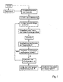
- FIG. 1 shows the method sequence for optimizing the excitation wavelengths at a fixed detection wavelength range.
- the user can either make the basic configuration of the system for the start of the optimization itself or use a database with stored emission and detection spectra by entering the dyes present in the sample. In the latter case will be on the Based on the database information the basic configuration of the system is made automatically.
- the further optimization parameters such as increment, excitation and detection bands are set automatically by the system. It is possible, but not mandatory, to control and edit these settings by the user before starting the optimization.
- the excitation wavelength ⁇ is varied as part of the optimization-which is carried out either on a reference sample or on the sample to be investigated itself-within the prescribed step size.
- a wavelength range can also be varied; the variation of a plurality of wavelength ranges is also possible.
- the set wavelength separation and suppression means are then adapted in the example and there is the detection of the returned light from the sample. It is expedient to record a complete image or a stack of images in the z-direction, but the detection can also take place only for a single point in the sample.
- the detected signals are processed to controlled variable R.
- R may be defined as the sum of the average intensities over all recorded images. For the controlled variable R thus determined, it is then compared whether the value determined in this step is greater than the values for the controlled variable R from the preceding steps.
- the configuration for the next excitation wavelength is made and again the controlled variable R is determined. If the controlled variable R is to be maximal in comparison with the previously determined values for the controlled variable R, then the set configuration is stored and only then is the next wavelength set. At the end of this variation of the excitation wavelength, the system is configured according to the settings set and stored for the maximum value for the controlled variable R.
- FIGS. 2a and 2b show the determination of controlled variables in the optimization of the excitation in the event that a wavelength-dependent cross-excitation of a plurality of dyes occurs.
- a direct separation of the signals or intensities is not possible in such a case.
- a first image region is defined, from which substantially the desired fluorescence is detected, as well as a second image region as a background region, from which fluorescence emitted predominantly by cross-excitation is detected.
- the average signals or intensities from both regions are shown as a function of the wavelength in FIG. 2a.
- the step size here was 5 nm.
- R b R a + w ⁇ S 1 S 1 Max
- FIG. 3 shows an expanded procedure compared to FIG. 1, in which case the position of the detection band or of the detection wavelength is additionally optimized at each wavelength step. This can be done for example by adjusting the release agent in connection with the introduction of different emission filters.
- a detection-optimized controlled variable R d is obtained in this way.
- the maximum of the controlled variable R is determined, for example by means of interpolation, and the system is configured accordingly.
- an illumination source 1 which comprises a light of a wavelength range continuously emitting or tunable in this range laser. From the illumination source 1 light is emitted and directed to first selection means 2. In these, the selection of a wavelength or a wavelength range, multiple wavelengths or wavelength ranges of the illumination light takes place. The selected for forwarding wavelengths or wavelength ranges are directed to release agent 3. These are used to separate the beam paths of illumination light and Dektetechnikslicht that comes from the sample 5. The arrows indicate the beam directions. Light of the selected wavelength ranges is directed to the sample 5 via an imaging module 4. If sample 5 is labeled with fluorescent dyes, so the illumination light is absorbed.
- the excited dyes emit light of other wavelengths, which is irradiated back to the separating means 3.
- the emission light which in addition to light of the emission wavelengths also contains a part of the illumination light, which has been reflected by the sample, for example, directed to suppressing means 6, where this portion of the illumination light is eliminated.
- the emission light is then directed to second selection means 7, in which case one or more wavelength ranges in which the emission light is to be detected are selected.
- the suppression means 6 and the second selection means 7 can also be designed as a single component.
- the light passes from the second selection means 7 to detection means 8, which may comprise, for example, a photomultiplier tube (PMT) or a CCD camera.
- PMT photomultiplier tube
- CCD camera a CCD camera
- the microscope according to the invention also comprises a control unit 9, which is connected to the illumination means 1, the first selection means 2, the separating means 3, the suppression means 6, the second selection means 7 and the detection means 8.
- the control unit 9 By means of the control unit 9, the individual components are controlled and, as described above, optimally matched.
- the algorithm can be processed via hardware circuits or via a suitable program, or a combination of both. Even a coordinated control by hand is possible.
- FIG. 5 shows, by way of example, an illumination source 1 with which light of different wavelengths and different wavelength ranges can be generated.
- an erbium fiber laser 10 which emits pulsed laser radiation at 1.56 ⁇ m and at a spectral width of the pulse of approximately 50 nm and a pulse length in the range of 100 fs or less by direct emission of the amplifier system.
- the frequency of this radiation can then be converted, for example, by continuum generation in a dispersion-shifted, doped glass fiber or in nonlinear crystals, even in combination.
- This method is for example of F. Tauser et al. in Opt. Let. Vol. 29, NO. 5 of 1 March 2004 described.
- From the radiation of the Erbium fiber laser 10 can be generated by means of nonlinear methods of frequency multiplication directly light of wavelengths 780 nm and 390 nm. Via nonlinear continuum generation, it is additionally possible to generate radiation with a pulse length of approximately 100 fs, which can be tuned in a range from 900 nm to 2000 nm. This in turn allows - also by non-linear methods of frequency doubling - a shift of the tuning range into the visible. In principle, this also covers the spectral range from 450 nm to 1000 nm.
- the spectral width of the laser pulses is between approximately 10 nm in the short-wave range and 45 nm in the long-wavelength range. In this way one obtains a single light source, which delivers laser radiation in the range of 390 nm or 225 nm to 2000 nm.
- the different wavelength ranges can be provided simultaneously while maintaining tunability within these ranges.
- a wavelength range or a plurality of wavelength ranges can also be divided externally. In the application this has the advantage that in experiments, the are designed for several simultaneously available laser lines, in the image recording no time-consuming tuning of the laser is necessary, as is the case for example with titanium sapphire systems.
- the key contrast mechanism is fluorescence.
- Fluorescent dyes have specific excitation mechanisms to which the laser radiation used for excitation must be tuned. In this case, a fluorescence signal can be generated, i. Photons of the laser light source are absorbed by the sample 5 when the laser emission and the excitation spectrum of the located in the sample 5 dye completely or partially overlap. In most cases, the emission spectrum of the fluorescent dye is shifted from the excitation spectrum due to the energy loss during absorption in the longer wavelength spectral range.
- FIG. 6 shows the conditions for a dual coloration and overlapping excitation and emission spectra of the dyes involved.
- the spectra of the first dye are shown by dotted lines, the Spectra of the second dye with dotted lines.
- excitation and emission spectra are superimposed, so that the unambiguous analysis of the experiment is only possible with exact knowledge of the respective spectra and simultaneous coordination of excitation and detection.
- a broadband emitting or tunable light source can therefore only be meaningfully used if it succeeds, despite the broadband of the excitation no false light to detect.
- the wavelength ranges for optimized excitation or detection for the two dyes are shown as rectangles, each with a different hatching. In the experiment, therefore, a large part of the laser light used for the excitation must be suppressed as completely as possible.
- additional components are required.
- a part is realized by means of the first selection means 2, in which in particular the use of acousto-optical filters is offered.
- These include the aforementioned AOTF and AOM.
- the width of the spectral window of an AOTF is approximately 30% to 50% greater than the spectral width of the laser radiation, so that in this case it is always possible to use approximately the entire energy of the laser.
- an AOTF is particularly suitable for spectral selection in the sense that spectral regions outside the selected window are effectively suppressed with the AOTF.
- it acts as a fast switch with a cutoff frequency of approximately 500 kHz and is able to modulate or adjust the energy of the laser radiation virtually continuously.
- FIG. 7 shows how one can achieve a variability in the width of the spectral window.
- broadband tunable lasers one shifts the center frequencies of laser and broadband AOTF against each other.
- the spectrum of the laser is shown in FIG. 7 as a uniform intensity distribution as a function of the wavelength with a solid line, the passband of the AOTF with a dotted line.
- the two arrows above the maxima of the two spectra, which coincide with the center frequencies, indicate the displaceability of the spectra against each other. If one now shifts the two center frequencies against each other, then only the part of the spectrum is transmitted and used in the overlapping area of the two spectral distributions, shown hatched here.
- Another possibility is the combination with an additional element, such as a variable bandpass filter based on finely graded interference filters.
- an additional element such as a variable bandpass filter based on finely graded interference filters.
- AOMs have a larger spectral width with respect to the set acousto-optic frequency than an AOTF, it is about 20 nm in the near infrared region, and between 20 and 40 nm in the visible region.
- Their tunable range in the near infrared is about 400 to 500 nm, in the visible spectrum at most 150 nm. The tunable range is thus somewhat lower than for an AOTF with about 250 nm in the visible spectral range.
- a series arrangement of several AOM is advantageous.
- FIG 8 such a series arrangement of three AOM 11, 12, 13 is shown. These are designed so that when passing through the AOM 11, 12 13 in the beam direction - in the image from left to right - increasingly longer-wavelength portions of the spectrum are selected and in each case the undeflected zeroth diffraction order of the above AOM 11 or 12 in the following AOM 12th or 13 occurs.
- the diffracted by the AOM 11, 12, 13 away from the optical axis orders are combined via a mirror 14 and dichroic splitter 15, 16 and coupled in parallel back into the beam path, whereas the undeflected orders are swallowed by a jet trap 17.
- the AOM 11 could divert the range from 450 to 490 nm, the AOM 12 the 490 to 640 nm wavelength range, and the AOM 13 the 640 to 700 nm wavelength range.
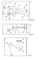
- the excitation radiation is separated from the emission radiation.
- HFT main color splitter
- FIGS. 9a and 10a these ports P 1 , P 2 and P 3 are indicated analogously.
- Both figures represent possible embodiments of such a HFT in a plan view, the corresponding side views are shown in Figs. 9b and 10b.
- these are so-called variable main color separators, which are flexible in the choice of the spectral bands for the excitation and detection.
- the excitation light and the fluorescent light emitted by the sample is spectrally decomposed and then modified in terms of wavelength so as to leave the HFT via the port provided P 2 or P 3 .
- excitation light and emission light are geometrically separated.
- the illumination light initially strikes a beam splitter 18 and passes through it unhindered.
- a prism 19 the light is spectrally split.
- a switching element 22 which may be a mirror array with individually controllable mirrors.
- the mirrors deflect the beam coming from the light source via a further deflection mirror 23, the prism 19 and a further beam splitter 24 either to the sample or into a beam trap 25.
- the HFT can also be constructed on a polarization-optical basis. Such an arrangement is shown in Figs. 10a and 10b.
- polarizing beam splitters 26 and 27 are used here.
- the switching element 28 is not used for directional deflection but for polarization rotation and can be used, for example, as a liquid crystal cell. which functions as a wavelength-dependent retardation plate, be designed.
- the suppression means 6 prevents the laser light used for excitation reaches the detector.
- so-called emission filters are used whose embodiment or geometry differs depending on the downstream detector.
- One possible arrangement is the use of a spectrally selective diaphragm with which the light used for the excitation is selectively blocked, as indicated in FIG.
- the light coming from the main color splitter is first spectrally split over a grating 29 and is directed via a mirror 30 to an aperture array 32 arranged in front of a line detector 31.
- the individual diaphragms of the diaphragm array 32 may be formed, for example, as beam traps and are preferably electronically controllable, so that they selectively enable or block the light path to the line detector 31. This additionally opens up the possibility of simultaneous detection of multiple spectral bands.
- a spectrally selective blocking can be achieved with a diaphragm array. If no large-area, integrating detector is used, the spectrally split radiation must be brought together again before the detection. This can be done by using at least one further dispersion element in combination with, for example, a 4-f arrangement.
- An example of such arrangements is shown in FIG.
- the light coming from the HFT initially strikes a grating 31 in which it is spectrally decomposed and imaged onto a lens 34.
- the single ones Rays then impinge in parallel on the aperture array 32, where they are transmitted or blocked depending on the wavelength. In the example shown, the upper beam is blocked, while the other two can pass.
- a lens 35 whose focal length is the same as in the lens 34 f, the rays are imaged onto a grating 36 in which they are reunited into a common steel, leave the suppressor 6 and directed to a single detector.
- a grating 36 in which they are reunited into a common steel, leave the suppressor 6 and directed to a single detector.
- prisms can also be used.
- FIG. 13 The arrangement used in Figure 13 is somewhat simplified from that shown in Figure 12 and is based on the fact that it does not depend on an exact superposition of the spectral components in the detection when the confocal filtering takes place in front of the blocking element.
- the spectrally decomposed and transmitted components are imaged directly onto the detector 8 by the lens 37.
- the aperture array used it is also possible to use a single aperture which can be embodied, for example, as a displaceable slot of variable width or simple edge, which is then moved by motor to the known position in the spectrum necessary for blocking the excitation spectrum.
- the aperture array 32 can also take over the function of the second selection means 7 and can be used to select the spectral ranges to be detected, in the case of the latter variant, this is additionally required. They may be arranged in front of or behind the suppression means 6 and consist of similar components as the first selection means 2.
- a tunable bandpass filter is also suitable as an emission filter for single channel detectors. The passband is to optimize the emission spectrum of the fluorescent dye, which is to be detected in the corresponding channel.
- FIG. 14 shows an arrangement with which a multi-line excitation with selectable spectral width is possible.
- an illumination source 1 which contains a broadband tunable or emitting laser
- the light can be selectively directed via a further mirror 39 to a narrowband AOTF 40 or a broadband AOTF 41 by means of a switchable mirror 38.
- the desired spectral width of the light used for fluorescence excitation can be selected, as indicated by the transmission spectra shown schematically.
- the bandwidth of the - preferably pulsed - laser light is not cropped, so that multi-photon processes in the sample are possible.
- the switchable mirror 38 can optionally also be designed as a fixed neutral divider, preferably with a division ratio of 50:50.
- a similar mirror 43 is used to reunite the radiation components from both channels.
- the combination of the two beam paths is also possible by means of a polarization-optical splitter.
- Another possibility for realizing the above-mentioned function is the use of an acousto-optical component with switchable spectral Width. In this case, the beam splitting and unification is eliminated.
- the unused radiation component of the zeroth diffraction order of the respective AOTF 40, 41 is in each case directed into a beam trap 42.
- the selected radiation strikes the separating means 3, which contain a variable or achromatic main color splitter.
- the fluorescence signal generated after the interaction with the sample 5 is directed to a single detector 44 via the second selection means 7, which are designed as a tunable bandpass filter emission filter and also take over the function of the suppressor 6.
- the second selection means 7 which are designed as a tunable bandpass filter emission filter and also take over the function of the suppressor 6.
- FIG. 15 shows an arrangement for multi-line excitation with a variably adjustable spectral width.
- the laser radiation coming from the illumination source 1 is either transmitted straight through or deflected by 90 ° via a fiber-optic switch 45 which is based on the piezoelectric retraction of optical components for directional deflection.
- the switch can be designed for the wavelength range from 450 to 700 nm, from 780 to 850 nm or from 1260 to 1650 nm.
- the switching time is in the millisecond range, so that fast can be switched back and forth between the two beam paths, in addition, the radiation can also be directed into a beam trap 46.
- the fiber optic switch 45 can perform only one switching function, the function of the intensity modulation or attenuation is in each case perceived by a downstream component, such as filter wheels 49, 50.
- the fiber optic switch 45 is also replaceable by a fast-switching mirror 38, or by a fixed dichroic splitter, which may be designed as long or short-pass when the wavelength ranges are fixed.
- the selected radiation is combined by a switchable mirror 43 again in a beam.
- a dichroic beam splitter, a neutral splitter, or a polarization-optical splitter can also be used.
- the radiation then impinges on the separating means 3, which as before may contain a tunable or achromatic HFT.
- the fluorescence signal generated after the interaction with the sample 5 is detected via the line detector 31.
- Suppression means 6 and second selection means 7 are realized by means of a single spectrally sensitive aperture array 32.
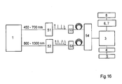
- FIG. 16 shows an arrangement in which one-shot and multiple-photon excitations are possible or combined, which is advantageous in particular for examination methods in which the sample 5 is manipulated.
- the illumination source 1 two broadband or broadband tunable spectral ranges are provided simultaneously.
- the illumination unit illustrated in FIG. 5 is suitable for this purpose.
- a wavelength range of 450 to 700 nm is provided in the visible and a wavelength range of 800 to 1300 nm in the near infrared.
- At least the near infrared radiation is in the form of femtosecond pulses in front. Both wavelength ranges can be simultaneously tuned to the experimental requirements in initially separate beam paths.
- the wavelength selection is preferably carried out by a narrow-band AOTF 51.
- a wavelength subrange is preferably selected by an AOM 52.
- the AOM 52 has the advantage over an AOTF of not truncating the spectral bandwidth of the femtosecond pulses.
- the radiation is also present in the visible spectral range in the form of pulses, it is also conceivable to extend the beam path by a further branch, which is not shown in Fig.16.
- radiation in the wavelength range of 225 to 350 nm can be generated via an additional frequency doubling.
- this frequency conversion of the spectral selection by means of an AOTF is followed, so that only the already selected radiation is doubled.
- a dispersion compensation unit 53 can be provided in all beam paths. These can be used to control the pulse length of the respective laser radiation. Due to the two separate beam paths for the selected spectral regions, the two beams have to be reproduced by a beam combiner 54 to be united.
- This beam combiner 54 can be realized in the prior art on the basis of dichroic splitter layers.
- the arrangement shown in Figure 16 can also be combined with the arrangement shown in Figure 14, so that on the one hand, the two wavelength ranges are available and on the other for the spectral range of 450 to 700 nm additionally the option is a broadband AOTF with to use the already mentioned advantages of maintaining the energetic and spectral or temporal structure of the laser light.
- Fluorescence Resonance Energy Transfer (FRET) experiments are particularly interesting applications for optimizing the excitation wavelength.
- FRET Fluorescence Resonance Energy Transfer
- only dye combinations can be used in which the emission wavelength of the donor dye with the excitation wavelength of the acceptor dye is superimposed in a certain range.
- a cross-excitation of both dyes with the excitation wavelength of the donor dye should be avoided as much as possible, since artefacts can not be excluded even with complex controls and accordingly less meaningful results are the result.
- the selection of an optimal excitation wave, ie as efficient as possible for the donor dye, but without excite the acceptor is a significant advantage, which increases the accuracy of the measurement accordingly and thus allows more precise statements about the examined structure.
- the free choice of the excitation wavelength opens the possibility to achieve a separation of cross excitation and FRET from the excitation with two or more adjacent lines and corresponding computational evaluation of the recorded fluorescence images.
- FLIM Fluorescence Lifetime Imaging Microscopy
- FCS fluorescence correlation spectroscopy
- a minimization of the crosstalk ie a minimization of the excitation of the longer wavelength dye by spectral tail of the shorter wavelength dye allows a more accurate evaluation of the correlation signal, since the process to be measured is not falsified. Also be tuned by the tuning option more dyes that are more suitable for the particular application. This is particularly important in the case of cross-correlation operating with at least two dyes.
- the invention also offers advantages in the identification of dyes by means of specific spectral information.
- free choice of excitation wavelengths it is often possible to evaluate the intensity difference of the signal at two or more discrete wavelengths to identify the signal of the dye.
- the discrete wavelengths are made available simultaneously, since otherwise the vote of the laser takes on a different wavelength too long to be used in living samples can.
- the wavelengths can be alternately switched in short order so that the fluorescence signal can be identified with almost no time delay.
- the selectivity of the method results from the free choice of wavelengths, whereby particularly characteristic signatures can be used taking into account the totality of the dyes present in the sample.
- the method can also be used with strongly scattering Samples such as tissue sections, prepared tissue or whole animals are used, since direct detection - so-called non-descanned detection - can be used. This opens, for example, access to more complex measurements of ion concentrations in the tissue section, since the signals can be detected with the required time resolution in the millisecond range and then simultaneously separated spectrally. The speed of the measurement is no longer dependent on the speed to tune the laser, but only on the speed of the scanner.
- the inventive method and the inventive arrangement are also advantageous for sample manipulation.
- This usually refers to the excitation of fluorochromes with the aim of spot bleaching, the photochemical modification - for example, uncaging, photo-conversion or photo-activation - or the physical destruction.
- uncaging requires both ultraviolet and near infrared wavelengths.
- image acquisition takes place in the visual area.
- uncaging and dye excitation can be efficiently performed to generate signals, optimizing imaging and minimizing sample loading.
Landscapes
- Physics & Mathematics (AREA)
- General Physics & Mathematics (AREA)
- Chemical & Material Sciences (AREA)
- Analytical Chemistry (AREA)
- Optics & Photonics (AREA)
- Health & Medical Sciences (AREA)
- Life Sciences & Earth Sciences (AREA)
- Biochemistry (AREA)
- Nuclear Medicine, Radiotherapy & Molecular Imaging (AREA)
- Pathology (AREA)
- Immunology (AREA)
- General Health & Medical Sciences (AREA)
- Engineering & Computer Science (AREA)
- Computer Vision & Pattern Recognition (AREA)
- General Engineering & Computer Science (AREA)
- Microscoopes, Condenser (AREA)
- Investigating, Analyzing Materials By Fluorescence Or Luminescence (AREA)
Applications Claiming Priority (1)
| Application Number | Priority Date | Filing Date | Title |
|---|---|---|---|
| DE102005059338A DE102005059338A1 (de) | 2005-12-08 | 2005-12-08 | Verfahren und Anordnung zur Untersuchung von Proben |
Publications (3)
| Publication Number | Publication Date |
|---|---|
| EP1795938A2 true EP1795938A2 (fr) | 2007-06-13 |
| EP1795938A3 EP1795938A3 (fr) | 2007-08-22 |
| EP1795938B1 EP1795938B1 (fr) | 2012-04-25 |
Family
ID=37808071
Family Applications (1)
| Application Number | Title | Priority Date | Filing Date |
|---|---|---|---|
| EP06023598A Not-in-force EP1795938B1 (fr) | 2005-12-08 | 2006-11-14 | Procédé et agencement destinés à l'analyse d'échantillons |
Country Status (5)
| Country | Link |
|---|---|
| US (1) | US7593158B2 (fr) |
| EP (1) | EP1795938B1 (fr) |
| JP (1) | JP5189277B2 (fr) |
| AT (1) | ATE555407T1 (fr) |
| DE (1) | DE102005059338A1 (fr) |
Cited By (8)
| Publication number | Priority date | Publication date | Assignee | Title |
|---|---|---|---|---|
| WO2008052821A1 (fr) * | 2006-11-03 | 2008-05-08 | Leica Microsystems Cms Gmbh | Configuration optique, et procédé pour commander et influencer un faisceau lumineux |
| WO2009066264A3 (fr) * | 2007-11-21 | 2009-09-11 | Light 4 Tech Firenze S.R.L. | Dispositif pour éclairer un objet avec une source de lumière multispectrale et détecter le spectre de la lumière émise |
| EP2175301A1 (fr) * | 2008-10-10 | 2010-04-14 | Carl Zeiss MicroImaging GmbH | Procédé d'imagerie d'échantillons utilisant un microscope, microscope et support de stockage de données |
| DE102010049212A1 (de) * | 2010-10-21 | 2012-04-26 | Rudolf Grosskopf | Simultane Fluoreszenzkorrelationsspektroskopie (sFCS) |
| WO2013149951A1 (fr) * | 2012-04-05 | 2013-10-10 | Carl Zeiss Microscopy Gmbh | Module séparateur de couleurs imageur et procédé permettant d'obtenir une image d'un champ d'objet dans un premier plan d'image et dans un second plan d'image |
| DE102014009142A1 (de) | 2014-06-20 | 2015-12-24 | Carl Zeiss Microscopy Gmbh | Verfahren und Vorrichtung zur Ansteuerung eines akustooptischen Bauteils |
| WO2017013033A1 (fr) * | 2015-07-20 | 2017-01-26 | Carl Zeiss Microscopy Gmbh | Microscopie sélective à balayage à haute résolution spectrale d'un échantillon |
| WO2022028694A1 (fr) * | 2020-08-05 | 2022-02-10 | Leica Microsystems Cms Gmbh | Procédé de réglage de l'éclairage dans un microscope à fluorescence et microscope à fluorescence correspondant |
Families Citing this family (33)
| Publication number | Priority date | Publication date | Assignee | Title |
|---|---|---|---|---|
| DE102006034914A1 (de) * | 2006-07-28 | 2008-01-31 | Carl Zeiss Microimaging Gmbh | Verfahren und Anordnung zur Ansteuerung eines Mikroskops, insbesondere eines Laser-Scanning-Mikroskopes |
| JP4933878B2 (ja) * | 2006-11-07 | 2012-05-16 | オリンパス株式会社 | 顕微鏡装置 |
| WO2009016806A1 (fr) * | 2007-07-27 | 2009-02-05 | Nikon Corporation | Dispositif de microscope à balayage laser multiphoton |
| US7932503B2 (en) * | 2008-05-16 | 2011-04-26 | David R. Parks | Method for pre-identification of spectral overlaps within fluorescent dye and detector combinations used in flow cytometry |
| DE102008049877A1 (de) * | 2008-09-30 | 2010-04-01 | Carl Zeiss Microimaging Gmbh | Verfahren zum Auswerten von Korrelationsspektroskopiemessdaten |
| US20100201800A1 (en) * | 2009-02-09 | 2010-08-12 | Olympus Corporation | Microscopy system |
| EP2411818B1 (fr) * | 2009-03-23 | 2017-12-13 | Neaspec GmbH | Microscope optique à champs proche |
| DE102009021993B4 (de) | 2009-05-19 | 2023-11-09 | Leica Microsystems Cms Gmbh | Scanmikroskop und zugehörige Verfahren |
| CN102298885B (zh) * | 2010-06-28 | 2013-02-13 | 徐佳义 | 图文视像展示结构 |
| US8524239B2 (en) | 2010-07-09 | 2013-09-03 | The United States of America as represented by the Secrectary, Department of Health and Human Services | Photosensitizing antibody-fluorophore conjugates |
| US10461880B2 (en) | 2010-08-26 | 2019-10-29 | Ciena Corporation | Flexible grid optical spectrum transmitter, receiver, and transceiver |
| US9197354B2 (en) | 2010-08-26 | 2015-11-24 | Ciena Corporation | Concatenated optical spectrum transmission systems and methods |
| EP2661652A1 (fr) | 2010-12-10 | 2013-11-13 | NKT Photonics A/S | Filtre accordable acousto-optique (aotf) pour une source à large bande destinée à un système de mesure de fluorescence |
| EP2668477B1 (fr) * | 2011-01-28 | 2020-09-09 | Onto Innovation Inc. | Procédé et mécanisme de réglage de capteur pour une détection sensible à la position |
| JP5516486B2 (ja) * | 2011-04-14 | 2014-06-11 | 株式会社島津製作所 | 分光測定装置及びプログラム |
| CN103781495A (zh) * | 2011-07-11 | 2014-05-07 | 美国政府(由卫生和人类服务部的部长所代表) | 光敏抗体-荧光团缀合物 |
| US9356413B2 (en) * | 2011-09-30 | 2016-05-31 | Olympus Corporation | Laser source apparatus and laser microscope |
| DE102014212657B4 (de) * | 2014-06-30 | 2016-03-10 | Fraunhofer-Gesellschaft zur Förderung der angewandten Forschung e.V. | System und Verfahren zur bedarfsgerechten Zuführung von Beleuchtungsenergie an Pflanzen |
| DE102014215352A1 (de) * | 2014-08-04 | 2016-02-04 | Berthold Technologies Gmbh & Co. Kg | Messgerät und Verfahren zum Bestimmen einer Messgröße |
| SG11201610052TA (en) | 2014-08-08 | 2017-02-27 | Us Health | Photo-controlled removal of targets in vitro and in vivo |
| JP6479407B2 (ja) * | 2014-10-20 | 2019-03-06 | 株式会社ニューフレアテクノロジー | 放射温度計及び温度測定方法 |
| CN108137701A (zh) | 2015-08-07 | 2018-06-08 | 美国政府(由卫生和人类服务部的部长所代表) | 用于治疗癌症的针对抑制细胞的近红外光免疫疗法(nir-pit) |
| CN119564879A (zh) | 2015-08-18 | 2025-03-07 | 乐天医药生技股份有限公司 | 用于光免疫疗法的组合物、联用及相关方法 |
| AU2016308286B2 (en) | 2015-08-18 | 2022-04-07 | Rakuten Medical, Inc. | Phthalocyanine dye conjugates and their storage |
| US10274806B2 (en) | 2015-11-06 | 2019-04-30 | Coherent, Inc. | Pulse-dividing method and apparatus for a pulsed carbon monoxide laser |
| EP3528049A1 (fr) * | 2018-02-20 | 2019-08-21 | ASML Netherlands B.V. | Procédé et appareil de métrologie ayant une largeur de bande accrue |
| EP3748413A1 (fr) * | 2019-06-03 | 2020-12-09 | Leica Microsystems CMS GmbH | Unité de commande pour microscope, système de microscope comprenant une telle unité de commande et procédé d'examen d'un échantillon |
| US11005227B2 (en) * | 2019-09-05 | 2021-05-11 | Nufern | Multi-wavelength adjustable-radial-mode fiber laser |
| DE102019134217A1 (de) | 2019-12-12 | 2021-06-17 | Leica Microsystems Cms Gmbh | Verfahren zum Konfigurieren eines automatisierten Mikroskops und Mittel zu dessen Durchführung sowie Mikroskopsystem |
| CN112904176B (zh) * | 2021-01-14 | 2022-08-16 | 强一半导体(苏州)有限公司 | 多节mems探针用多参数检测光机电算控一体化方法 |
| CN112904177B (zh) * | 2021-01-14 | 2022-05-10 | 强一半导体(苏州)有限公司 | 多节mems探针用多参数检测光机电算控一体化装置 |
| EP4092466A1 (fr) * | 2021-05-21 | 2022-11-23 | Leica Microsystems CMS GmbH | Procédé d'obtention d'une valeur de fonctionnement d'un paramètre d'éclairage pour examiner un échantillon fluorescent, procédé d'examen d'un échantillon fluorescent, système de microscope et programme informatique |
| CN115607103A (zh) * | 2021-07-12 | 2023-01-17 | 中国科学院上海光学精密机械研究所 | 一种近红外波长可调谐的荧光成像装置 |
Family Cites Families (30)
| Publication number | Priority date | Publication date | Assignee | Title |
|---|---|---|---|---|
| DE1915102A1 (de) | 1969-03-25 | 1970-10-01 | Vogel Ignaz Kg | Hydropneumatische Druckfeder |
| FR2557985B1 (fr) | 1984-01-10 | 1987-04-24 | Sfena | Deflecteur acousto-optique polychromatique |
| JPH0338614A (ja) * | 1989-07-05 | 1991-02-19 | Pioneer Electron Corp | 音響光学変調装置 |
| CA2084923A1 (fr) * | 1991-12-20 | 1993-06-21 | Ronald E. Stafford | Spectrometre a modulateur de lumiere spatial |
| DE19510102C1 (de) * | 1995-03-20 | 1996-10-02 | Rainer Dr Uhl | Konfokales Fluoreszenzmikroskop |
| DE19829944C2 (de) * | 1998-07-04 | 2002-03-28 | Zeiss Carl Jena Gmbh | Verfahren und Anordnung zur Gerätekonfiguration eines Fluoreszenz-Laserscanmikroskops |
| DE19835072A1 (de) * | 1998-08-04 | 2000-02-10 | Zeiss Carl Jena Gmbh | Anordnung zur Beleuchtung und/oder Detektion in einem Mikroskop |
| DE19835070B4 (de) * | 1998-08-04 | 2006-03-16 | Carl Zeiss Jena Gmbh | Anordnung zur einstellbaren wellenlängenabhängigen Detektion in einem Fluoreszenzmikroskop |
| US6377344B2 (en) * | 1998-08-04 | 2002-04-23 | Carl Zeiss Jena Gmbh | Adjustable coupling in and/or detection of one or more wavelengths in a microscope |
| AT410718B (de) * | 1998-10-28 | 2003-07-25 | Schindler Hansgeorg Dr | Vorrichtung zur visualisierung von molekülen |
| JP2000199855A (ja) * | 1998-11-02 | 2000-07-18 | Olympus Optical Co Ltd | 走査型光学顕微鏡装置 |
| DE19936573A1 (de) | 1998-12-22 | 2001-02-08 | Zeiss Carl Jena Gmbh | Anordnung zur Separierung von Anregungs- und Emissionslicht in einem Mikroskop |
| DE19916749B4 (de) * | 1999-04-14 | 2004-02-12 | Carl Zeiss Jena Gmbh | Verfahren zur Untersuchung von Proben |
| DE10017825C2 (de) * | 2000-04-10 | 2003-05-08 | Till I D Gmbh | Polychromatische Fluoreszenz-Meßvorrichtung |
| EP1164406B1 (fr) * | 2000-06-17 | 2019-04-17 | Leica Microsystems CMS GmbH | Méthode et appareil pour illuminer un objet |
| DE20122783U1 (de) * | 2000-06-17 | 2007-11-15 | Leica Microsystems Cms Gmbh | Anordnung zum Untersuchen mikroskopischer Präparate mit einem Scanmikroskop und Beleuchtungseinrichtung für ein Scanmikroskop |
| DE20122782U1 (de) * | 2000-06-17 | 2007-11-15 | Leica Microsystems Cms Gmbh | Beleuchtungseinrichtung |
| EP1164402B1 (fr) * | 2000-06-17 | 2010-04-28 | Leica Microsystems CMS GmbH | Microscope à balayage avec illumination multibande et élément optique pour un microscope à balayage avec illumination multibande |
| US6958811B2 (en) * | 2000-06-29 | 2005-10-25 | Carl Zeiss Jena Gmbh | Method for the detection of dyes in fluorescence microscopy |
| US6858852B2 (en) * | 2000-08-08 | 2005-02-22 | Carl Zeiss Jena Gmbh | Method and apparatus for rapid change of fluorescence bands in the detection of dyes in fluorescence microscopy |
| DE10038526B4 (de) | 2000-08-08 | 2004-09-02 | Carl Zeiss Jena Gmbh | Verfahren und Anordnung zur Erfassung des wellenlängenabhängigen Verhaltens einer beleuchteten Probe |
| DE10137158B4 (de) | 2001-07-30 | 2005-08-04 | Leica Microsystems Heidelberg Gmbh | Verfahren zur Scanmikroskopie und Scanmikroskop |
| DE10151217B4 (de) | 2001-10-16 | 2012-05-16 | Carl Zeiss Microlmaging Gmbh | Verfahren zum Betrieb eines Laser-Scanning-Mikroskops |
| DE10222359B4 (de) * | 2002-05-21 | 2005-01-05 | Max Planck-Gesellschaft zur Förderung der Wissenschaften e.V. | Verfahren zur spektral differenzierenden, bildgebenden Messung von Fluoreszenzlicht |
| DE10241472B4 (de) * | 2002-09-04 | 2019-04-11 | Carl Zeiss Microscopy Gmbh | Verfahren und Anordnung zur einstellbaren Veränderung von Beleuchtungslicht und/oder Probenlicht bezüglich seiner spektralen Zusammensetzung und/oder Intensität |
| JP2004325200A (ja) * | 2003-04-24 | 2004-11-18 | Hitachi Ltd | 組織内物質濃度測定装置 |
| JP4583723B2 (ja) * | 2003-04-30 | 2010-11-17 | オリンパス株式会社 | 試料を染色した蛍光試薬のレーザ走査顕微鏡を用いた判別方法 |
| DE10339311B4 (de) * | 2003-08-27 | 2006-04-27 | Leica Microsystems Cms Gmbh | System und Verfahren zur Einstellung eines Fluoreszenzspektralmesssystems zur Mikroskopie |
| US7223961B2 (en) * | 2003-08-28 | 2007-05-29 | Leica Microsystems Cms Gmbh | Device for selectively detecting specific wavelength components of a light beam |
| DE102004017018A1 (de) * | 2004-04-02 | 2005-10-20 | Leica Microsystems | Verfahren zur Untersuchung einer Probe |
-
2005
- 2005-12-08 DE DE102005059338A patent/DE102005059338A1/de not_active Withdrawn
-
2006
- 2006-01-12 US US11/330,384 patent/US7593158B2/en not_active Expired - Fee Related
- 2006-11-14 EP EP06023598A patent/EP1795938B1/fr not_active Not-in-force
- 2006-11-14 AT AT06023598T patent/ATE555407T1/de active
- 2006-11-30 JP JP2006322869A patent/JP5189277B2/ja not_active Expired - Fee Related
Cited By (13)
| Publication number | Priority date | Publication date | Assignee | Title |
|---|---|---|---|---|
| WO2008052821A1 (fr) * | 2006-11-03 | 2008-05-08 | Leica Microsystems Cms Gmbh | Configuration optique, et procédé pour commander et influencer un faisceau lumineux |
| US8503084B2 (en) | 2006-11-03 | 2013-08-06 | Leica Microsystems Cms Gmbh | Optical arrangement and method for controlling and influencing a light ray |
| WO2009066264A3 (fr) * | 2007-11-21 | 2009-09-11 | Light 4 Tech Firenze S.R.L. | Dispositif pour éclairer un objet avec une source de lumière multispectrale et détecter le spectre de la lumière émise |
| EP2175301A1 (fr) * | 2008-10-10 | 2010-04-14 | Carl Zeiss MicroImaging GmbH | Procédé d'imagerie d'échantillons utilisant un microscope, microscope et support de stockage de données |
| US8294897B2 (en) | 2008-10-10 | 2012-10-23 | Carl Zeiss Microimaging Gmbh | Method for imaging a sample using a microscope, and microscope and data storage center |
| DE102010049212A1 (de) * | 2010-10-21 | 2012-04-26 | Rudolf Grosskopf | Simultane Fluoreszenzkorrelationsspektroskopie (sFCS) |
| WO2013149951A1 (fr) * | 2012-04-05 | 2013-10-10 | Carl Zeiss Microscopy Gmbh | Module séparateur de couleurs imageur et procédé permettant d'obtenir une image d'un champ d'objet dans un premier plan d'image et dans un second plan d'image |
| DE102014009142A1 (de) | 2014-06-20 | 2015-12-24 | Carl Zeiss Microscopy Gmbh | Verfahren und Vorrichtung zur Ansteuerung eines akustooptischen Bauteils |
| US10302490B2 (en) | 2014-06-20 | 2019-05-28 | Carl Zeiss Microscopy Gmbh | Method and apparatus for actuating an acousto-optical component |
| WO2017013033A1 (fr) * | 2015-07-20 | 2017-01-26 | Carl Zeiss Microscopy Gmbh | Microscopie sélective à balayage à haute résolution spectrale d'un échantillon |
| US10649188B2 (en) | 2015-07-20 | 2020-05-12 | Carl Zeiss Microscopy Gmbh | High-resolution spectrally selective scanning microscopy of a sample |
| WO2022028694A1 (fr) * | 2020-08-05 | 2022-02-10 | Leica Microsystems Cms Gmbh | Procédé de réglage de l'éclairage dans un microscope à fluorescence et microscope à fluorescence correspondant |
| US12313830B2 (en) | 2020-08-05 | 2025-05-27 | Leica Microsystems Cms Gmbh | Method for adjusting the illumination in a fluorescence microscope, and corresponding fluorescence microscope |
Also Published As
| Publication number | Publication date |
|---|---|
| US20070133086A1 (en) | 2007-06-14 |
| JP2007155722A (ja) | 2007-06-21 |
| DE102005059338A1 (de) | 2007-06-14 |
| EP1795938A3 (fr) | 2007-08-22 |
| US7593158B2 (en) | 2009-09-22 |
| ATE555407T1 (de) | 2012-05-15 |
| EP1795938B1 (fr) | 2012-04-25 |
| JP5189277B2 (ja) | 2013-04-24 |
Similar Documents
| Publication | Publication Date | Title |
|---|---|---|
| EP1795938B1 (fr) | Procédé et agencement destinés à l'analyse d'échantillons | |
| EP3217205B1 (fr) | Dispositif et procédé de microscopie par balayage multizone | |
| EP2149070B1 (fr) | Élément filtrant acousto-optique ajustable | |
| EP1055144B1 (fr) | Systeme optique a element spectroselectif | |
| EP0600334B1 (fr) | Procédé pour la détermination de matériaux et/ou de leurs propriétés et appareil à cette fin | |
| EP2823347B1 (fr) | Microscope optique à balayage, à détection spectrale | |
| DE69714021T4 (de) | Lichtmikroskop mit akustooptisch abstimmbaren filtern | |
| DE10038526B4 (de) | Verfahren und Anordnung zur Erfassung des wellenlängenabhängigen Verhaltens einer beleuchteten Probe | |
| EP3042232B1 (fr) | Microscope à balayage et séparateur de faisceaux principaux pour microscope à balayage | |
| DE10339311B4 (de) | System und Verfahren zur Einstellung eines Fluoreszenzspektralmesssystems zur Mikroskopie | |
| WO1995007447A1 (fr) | Dispositif de selection et de detection d'au moins deux zones spectrales d'un faisceau lumineux | |
| DE102011106916A1 (de) | Konfokales Auflicht-Rastermikroskop | |
| DE102013224463B4 (de) | Vorrichtung zur Ermittlung von Fluoreszenzeigenschaften von Proben | |
| DE20216583U1 (de) | Mikroskop und Durchflusszytometer | |
| EP1141763B2 (fr) | Agencement servant a separer la lumiere d'excitation et la lumiere d'emission dans un microscope | |
| DE10227111B4 (de) | Spektralmikroskop und Verfahren zur Datenaufnahme mit einem Spektralmikroskop | |
| DE10228374A1 (de) | Verfahren zur Mikroskopie und Mikroskop | |
| EP3042169A1 (fr) | Microscope et concentrateur de faisceau acousto-optique pour microscope | |
| DE102014008098A1 (de) | Spektral flexible, schnell umschaltbare optische Filtervorrichtung | |
| EP1719998B1 (fr) | Appareil de microdissection au laser | |
| DE102004029733A1 (de) | Rastermikroskop und Verfahren zur Rastermikroskopie | |
| DE19748458C1 (de) | Vorrichtung zur Erzeugung von ultrakurzen Lichtimpulsen, insbesondere zur Anwendung in einer Spektrometer-Vorrichtung |
Legal Events
| Date | Code | Title | Description |
|---|---|---|---|
| PUAI | Public reference made under article 153(3) epc to a published international application that has entered the european phase |
Free format text: ORIGINAL CODE: 0009012 |
|
| 17P | Request for examination filed |
Effective date: 20061114 |
|
| AK | Designated contracting states |
Kind code of ref document: A2 Designated state(s): AT BE BG CH CY CZ DE DK EE ES FI FR GB GR HU IE IS IT LI LT LU LV MC NL PL PT RO SE SI SK TR |
|
| AX | Request for extension of the european patent |
Extension state: AL BA HR MK YU |
|
| PUAL | Search report despatched |
Free format text: ORIGINAL CODE: 0009013 |
|
| AK | Designated contracting states |
Kind code of ref document: A3 Designated state(s): AT BE BG CH CY CZ DE DK EE ES FI FR GB GR HU IE IS IT LI LT LU LV MC NL PL PT RO SE SI SK TR |
|
| AX | Request for extension of the european patent |
Extension state: AL BA HR MK YU |
|
| RIC1 | Information provided on ipc code assigned before grant |
Ipc: G02B 27/10 20060101ALI20070719BHEP Ipc: G02B 27/14 20060101ALI20070719BHEP Ipc: G01N 21/64 20060101ALI20070719BHEP Ipc: G02B 21/00 20060101AFI20070321BHEP |
|
| 17Q | First examination report despatched |
Effective date: 20080306 |
|
| AKX | Designation fees paid |
Designated state(s): AT BE BG CH CY CZ DE DK EE ES FI FR GB GR HU IE IS IT LI LT LU LV MC NL PL PT RO SE SI SK TR |
|
| GRAP | Despatch of communication of intention to grant a patent |
Free format text: ORIGINAL CODE: EPIDOSNIGR1 |
|
| RIC1 | Information provided on ipc code assigned before grant |
Ipc: G02B 27/14 20060101ALI20111117BHEP Ipc: G01N 21/64 20060101ALI20111117BHEP Ipc: G02B 21/16 20060101ALI20111117BHEP Ipc: G02B 27/10 20060101ALI20111117BHEP Ipc: G02B 21/00 20060101AFI20111117BHEP |
|
| GRAS | Grant fee paid |
Free format text: ORIGINAL CODE: EPIDOSNIGR3 |
|
| GRAA | (expected) grant |
Free format text: ORIGINAL CODE: 0009210 |
|
| RIN1 | Information on inventor provided before grant (corrected) |
Inventor name: WILHELM, STEFAN Inventor name: KEMPE, MICHAEL, DR. Inventor name: SIMBUERGER, EVA, DR. |
|
| AK | Designated contracting states |
Kind code of ref document: B1 Designated state(s): AT BE BG CH CY CZ DE DK EE ES FI FR GB GR HU IE IS IT LI LT LU LV MC NL PL PT RO SE SI SK TR |
|
| REG | Reference to a national code |
Ref country code: GB Ref legal event code: FG4D Free format text: NOT ENGLISH |
|
| REG | Reference to a national code |
Ref country code: CH Ref legal event code: EP |
|
| REG | Reference to a national code |
Ref country code: AT Ref legal event code: REF Ref document number: 555407 Country of ref document: AT Kind code of ref document: T Effective date: 20120515 |
|
| REG | Reference to a national code |
Ref country code: IE Ref legal event code: FG4D Free format text: LANGUAGE OF EP DOCUMENT: GERMAN |
|
| REG | Reference to a national code |
Ref country code: DE Ref legal event code: R096 Ref document number: 502006011341 Country of ref document: DE Effective date: 20120614 |
|
| REG | Reference to a national code |
Ref country code: NL Ref legal event code: VDEP Effective date: 20120425 |
|
| LTIE | Lt: invalidation of european patent or patent extension |
Effective date: 20120425 |
|
| PG25 | Lapsed in a contracting state [announced via postgrant information from national office to epo] |
Ref country code: SE Free format text: LAPSE BECAUSE OF FAILURE TO SUBMIT A TRANSLATION OF THE DESCRIPTION OR TO PAY THE FEE WITHIN THE PRESCRIBED TIME-LIMIT Effective date: 20120425 Ref country code: IS Free format text: LAPSE BECAUSE OF FAILURE TO SUBMIT A TRANSLATION OF THE DESCRIPTION OR TO PAY THE FEE WITHIN THE PRESCRIBED TIME-LIMIT Effective date: 20120825 Ref country code: PL Free format text: LAPSE BECAUSE OF FAILURE TO SUBMIT A TRANSLATION OF THE DESCRIPTION OR TO PAY THE FEE WITHIN THE PRESCRIBED TIME-LIMIT Effective date: 20120425 Ref country code: LT Free format text: LAPSE BECAUSE OF FAILURE TO SUBMIT A TRANSLATION OF THE DESCRIPTION OR TO PAY THE FEE WITHIN THE PRESCRIBED TIME-LIMIT Effective date: 20120425 Ref country code: CY Free format text: LAPSE BECAUSE OF FAILURE TO SUBMIT A TRANSLATION OF THE DESCRIPTION OR TO PAY THE FEE WITHIN THE PRESCRIBED TIME-LIMIT Effective date: 20120425 Ref country code: FI Free format text: LAPSE BECAUSE OF FAILURE TO SUBMIT A TRANSLATION OF THE DESCRIPTION OR TO PAY THE FEE WITHIN THE PRESCRIBED TIME-LIMIT Effective date: 20120425 |
|
| PG25 | Lapsed in a contracting state [announced via postgrant information from national office to epo] |
Ref country code: GR Free format text: LAPSE BECAUSE OF FAILURE TO SUBMIT A TRANSLATION OF THE DESCRIPTION OR TO PAY THE FEE WITHIN THE PRESCRIBED TIME-LIMIT Effective date: 20120726 Ref country code: LV Free format text: LAPSE BECAUSE OF FAILURE TO SUBMIT A TRANSLATION OF THE DESCRIPTION OR TO PAY THE FEE WITHIN THE PRESCRIBED TIME-LIMIT Effective date: 20120425 Ref country code: PT Free format text: LAPSE BECAUSE OF FAILURE TO SUBMIT A TRANSLATION OF THE DESCRIPTION OR TO PAY THE FEE WITHIN THE PRESCRIBED TIME-LIMIT Effective date: 20120827 Ref country code: SI Free format text: LAPSE BECAUSE OF FAILURE TO SUBMIT A TRANSLATION OF THE DESCRIPTION OR TO PAY THE FEE WITHIN THE PRESCRIBED TIME-LIMIT Effective date: 20120425 |
|
| PG25 | Lapsed in a contracting state [announced via postgrant information from national office to epo] |
Ref country code: EE Free format text: LAPSE BECAUSE OF FAILURE TO SUBMIT A TRANSLATION OF THE DESCRIPTION OR TO PAY THE FEE WITHIN THE PRESCRIBED TIME-LIMIT Effective date: 20120425 Ref country code: SK Free format text: LAPSE BECAUSE OF FAILURE TO SUBMIT A TRANSLATION OF THE DESCRIPTION OR TO PAY THE FEE WITHIN THE PRESCRIBED TIME-LIMIT Effective date: 20120425 Ref country code: DK Free format text: LAPSE BECAUSE OF FAILURE TO SUBMIT A TRANSLATION OF THE DESCRIPTION OR TO PAY THE FEE WITHIN THE PRESCRIBED TIME-LIMIT Effective date: 20120425 Ref country code: RO Free format text: LAPSE BECAUSE OF FAILURE TO SUBMIT A TRANSLATION OF THE DESCRIPTION OR TO PAY THE FEE WITHIN THE PRESCRIBED TIME-LIMIT Effective date: 20120425 Ref country code: NL Free format text: LAPSE BECAUSE OF FAILURE TO SUBMIT A TRANSLATION OF THE DESCRIPTION OR TO PAY THE FEE WITHIN THE PRESCRIBED TIME-LIMIT Effective date: 20120425 Ref country code: CZ Free format text: LAPSE BECAUSE OF FAILURE TO SUBMIT A TRANSLATION OF THE DESCRIPTION OR TO PAY THE FEE WITHIN THE PRESCRIBED TIME-LIMIT Effective date: 20120425 |
|
| REG | Reference to a national code |
Ref country code: DE Ref legal event code: R082 Ref document number: 502006011341 Country of ref document: DE Representative=s name: GEYER, FEHNERS & PARTNER (G.B.R.), DE |
|
| PG25 | Lapsed in a contracting state [announced via postgrant information from national office to epo] |
Ref country code: IT Free format text: LAPSE BECAUSE OF FAILURE TO SUBMIT A TRANSLATION OF THE DESCRIPTION OR TO PAY THE FEE WITHIN THE PRESCRIBED TIME-LIMIT Effective date: 20120425 |
|
| PLBE | No opposition filed within time limit |
Free format text: ORIGINAL CODE: 0009261 |
|
| STAA | Information on the status of an ep patent application or granted ep patent |
Free format text: STATUS: NO OPPOSITION FILED WITHIN TIME LIMIT |
|
| REG | Reference to a national code |
Ref country code: DE Ref legal event code: R081 Ref document number: 502006011341 Country of ref document: DE Owner name: CARL ZEISS MICROSCOPY GMBH, DE Free format text: FORMER OWNER: CARL ZEISS MICROIMAGING GMBH, 07745 JENA, DE Effective date: 20130204 Ref country code: DE Ref legal event code: R081 Ref document number: 502006011341 Country of ref document: DE Owner name: CARL ZEISS MICROSCOPY GMBH, DE Free format text: FORMER OWNER: CARL ZEISS MICROIMAGING GMBH, 07745 JENA, DE Effective date: 20120425 Ref country code: DE Ref legal event code: R082 Ref document number: 502006011341 Country of ref document: DE Representative=s name: GEYER, FEHNERS & PARTNER (G.B.R.), DE Effective date: 20130204 Ref country code: DE Ref legal event code: R082 Ref document number: 502006011341 Country of ref document: DE Representative=s name: PATENTANWAELTE GEYER, FEHNERS & PARTNER MBB, DE Effective date: 20130204 |
|
| 26N | No opposition filed |
Effective date: 20130128 |
|
| PG25 | Lapsed in a contracting state [announced via postgrant information from national office to epo] |
Ref country code: ES Free format text: LAPSE BECAUSE OF FAILURE TO SUBMIT A TRANSLATION OF THE DESCRIPTION OR TO PAY THE FEE WITHIN THE PRESCRIBED TIME-LIMIT Effective date: 20120805 |
|
| REG | Reference to a national code |
Ref country code: DE Ref legal event code: R097 Ref document number: 502006011341 Country of ref document: DE Effective date: 20130128 |
|
| BERE | Be: lapsed |
Owner name: CARL ZEISS MICROIMAGING G.M.B.H. Effective date: 20121130 |
|
| REG | Reference to a national code |
Ref country code: CH Ref legal event code: PL |
|
| PG25 | Lapsed in a contracting state [announced via postgrant information from national office to epo] |
Ref country code: LI Free format text: LAPSE BECAUSE OF NON-PAYMENT OF DUE FEES Effective date: 20121130 Ref country code: CH Free format text: LAPSE BECAUSE OF NON-PAYMENT OF DUE FEES Effective date: 20121130 Ref country code: BG Free format text: LAPSE BECAUSE OF FAILURE TO SUBMIT A TRANSLATION OF THE DESCRIPTION OR TO PAY THE FEE WITHIN THE PRESCRIBED TIME-LIMIT Effective date: 20120725 |
|
| REG | Reference to a national code |
Ref country code: IE Ref legal event code: MM4A |
|
| PG25 | Lapsed in a contracting state [announced via postgrant information from national office to epo] |
Ref country code: BE Free format text: LAPSE BECAUSE OF NON-PAYMENT OF DUE FEES Effective date: 20121130 |
|
| PG25 | Lapsed in a contracting state [announced via postgrant information from national office to epo] |
Ref country code: IE Free format text: LAPSE BECAUSE OF NON-PAYMENT OF DUE FEES Effective date: 20121114 |
|
| REG | Reference to a national code |
Ref country code: AT Ref legal event code: MM01 Ref document number: 555407 Country of ref document: AT Kind code of ref document: T Effective date: 20121130 |
|
| PG25 | Lapsed in a contracting state [announced via postgrant information from national office to epo] |
Ref country code: AT Free format text: LAPSE BECAUSE OF NON-PAYMENT OF DUE FEES Effective date: 20121130 |
|
| PG25 | Lapsed in a contracting state [announced via postgrant information from national office to epo] |
Ref country code: MC Free format text: LAPSE BECAUSE OF NON-PAYMENT OF DUE FEES Effective date: 20121130 Ref country code: TR Free format text: LAPSE BECAUSE OF FAILURE TO SUBMIT A TRANSLATION OF THE DESCRIPTION OR TO PAY THE FEE WITHIN THE PRESCRIBED TIME-LIMIT Effective date: 20120425 |
|
| PG25 | Lapsed in a contracting state [announced via postgrant information from national office to epo] |
Ref country code: LU Free format text: LAPSE BECAUSE OF NON-PAYMENT OF DUE FEES Effective date: 20121114 |
|
| PG25 | Lapsed in a contracting state [announced via postgrant information from national office to epo] |
Ref country code: HU Free format text: LAPSE BECAUSE OF FAILURE TO SUBMIT A TRANSLATION OF THE DESCRIPTION OR TO PAY THE FEE WITHIN THE PRESCRIBED TIME-LIMIT Effective date: 20061114 |
|
| REG | Reference to a national code |
Ref country code: FR Ref legal event code: PLFP Year of fee payment: 10 |
|
| REG | Reference to a national code |
Ref country code: FR Ref legal event code: PLFP Year of fee payment: 11 |
|
| REG | Reference to a national code |
Ref country code: FR Ref legal event code: PLFP Year of fee payment: 12 |
|
| PGFP | Annual fee paid to national office [announced via postgrant information from national office to epo] |
Ref country code: DE Payment date: 20181120 Year of fee payment: 13 |
|
| PGFP | Annual fee paid to national office [announced via postgrant information from national office to epo] |
Ref country code: FR Payment date: 20181123 Year of fee payment: 13 Ref country code: GB Payment date: 20181120 Year of fee payment: 13 |
|
| REG | Reference to a national code |
Ref country code: DE Ref legal event code: R119 Ref document number: 502006011341 Country of ref document: DE |
|
| GBPC | Gb: european patent ceased through non-payment of renewal fee |
Effective date: 20191114 |
|
| PG25 | Lapsed in a contracting state [announced via postgrant information from national office to epo] |
Ref country code: DE Free format text: LAPSE BECAUSE OF NON-PAYMENT OF DUE FEES Effective date: 20200603 Ref country code: GB Free format text: LAPSE BECAUSE OF NON-PAYMENT OF DUE FEES Effective date: 20191114 Ref country code: FR Free format text: LAPSE BECAUSE OF NON-PAYMENT OF DUE FEES Effective date: 20191130 |