EP1796238B1 - Détection et protection d'un arc de défaut à courant continu - Google Patents
Détection et protection d'un arc de défaut à courant continu Download PDFInfo
- Publication number
- EP1796238B1 EP1796238B1 EP06256200A EP06256200A EP1796238B1 EP 1796238 B1 EP1796238 B1 EP 1796238B1 EP 06256200 A EP06256200 A EP 06256200A EP 06256200 A EP06256200 A EP 06256200A EP 1796238 B1 EP1796238 B1 EP 1796238B1
- Authority
- EP
- European Patent Office
- Prior art keywords
- arc
- signal value
- signal
- electrical
- software module
- Prior art date
- Legal status (The legal status is an assumption and is not a legal conclusion. Google has not performed a legal analysis and makes no representation as to the accuracy of the status listed.)
- Ceased
Links
Images




Classifications
-
- H—ELECTRICITY
- H02—GENERATION; CONVERSION OR DISTRIBUTION OF ELECTRIC POWER
- H02H—EMERGENCY PROTECTIVE CIRCUIT ARRANGEMENTS
- H02H1/00—Details of emergency protective circuit arrangements
- H02H1/0007—Details of emergency protective circuit arrangements concerning the detecting means
- H02H1/0015—Using arc detectors
-
- H—ELECTRICITY
- H02—GENERATION; CONVERSION OR DISTRIBUTION OF ELECTRIC POWER
- H02H—EMERGENCY PROTECTIVE CIRCUIT ARRANGEMENTS
- H02H3/00—Emergency protective circuit arrangements for automatic disconnection directly responsive to an undesired change from normal electric working condition with or without subsequent reconnection ; integrated protection
- H02H3/08—Emergency protective circuit arrangements for automatic disconnection directly responsive to an undesired change from normal electric working condition with or without subsequent reconnection ; integrated protection responsive to excess current
- H02H3/087—Emergency protective circuit arrangements for automatic disconnection directly responsive to an undesired change from normal electric working condition with or without subsequent reconnection ; integrated protection responsive to excess current for DC applications
Definitions
- This invention relates to identification of electrical arc faults and, more particularly, to methodology for identifying the occurrence of DC arc events.
- a thermal circuit breaker trips to open the circuit when the temperature exceeds a predetermined temperature.
- a solid-state power controller monitors electrical current and trips if the current exceeds a preset energy rating.
- An additional hard-wired arc-detecting circuit may be utilized in conjunction with the thermal circuit breaker to detect a DC electric arc and initiate a trip electro-mechanically.
- an additional hard-wired arc-detecting circuit may be utilized in conjunction with a power controller to detect a DC electric arc and initiate a trip.
- Use of hard-wired circuitry may increase the size and weight of the electrical protection device and add expense.
- US Patent Application US 2005/0135025 A1 discloses a method of parallel DC arc detection comprising the step of acquiring a signal representing DC electrical current over a time period.
- a method of parallel DC arc event detection is defined as specified in claim 1.
- a device for detecting parallel DC are events, including a means to open a switch is defined in claim 5.
- Figure 1 illustrates selected portions of an example electrical system 10 having a solid-state power controller 12 that receives DC electrical power from a power source 14.
- the solid-state power controller 12 includes a sensor 18 for sensing the DC electrical current and a solid-state switch 20 for selectively switching DC electrical power to a desired load 16.
- a software module 22 is integrally connected with the sensor 18 and the solid-state switch 20.
- the software module 22 acquires a signal representing the DC electrical current and analyzes the signal to identify occurrences of DC arc faults, as will be described below.
- the software module 22 includes a digital counter 25, such as an accumulator, and is capable of annunciating the fault through a communication interface such as a serial communication interface, other known interface, or with an indicator 27.
- a digital counter 25 such as an accumulator
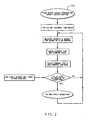
- the software module 22 acquires the signal in a generally known manner, which includes high speed signal processing and conditioning shown starting at step 24.
- Figure 3 shows parallel DC arc event detection.
- the software module 22 analyzes the signal 30 for both parallel and series DC arc events.
- a parallel DC arc fault refers to a predetermined number of DC arc events within a selected time period.
- a series DC arc event refers to change in average DC electrical current values over several predetermined time periods. Multiple DC arc events constitute a DC arc fault.
- the example electrical system 10 ( Figure 1 ) provides the benefit of utilizing a single sensor 18 for both overcurrent protection and arc event or fault protection.
- the signal 30 represents the DC electrical current magnitude versus time.
- the software module 22 monitors the signal 30 over a sliding time period X and identifies a maximum at 32 and a minimum at 34.
- the software module 22 determines a difference D between the maximum 32 and the minimum 34, and compares the result to a predetermined threshold according to the equation: Maximum - Minimum > Threshold
- the software module 22 identifies a DC arc event when the result is greater than the predetermined threshold. If a predetermined number of DC arc events occur within a selected period, the software module 22 concludes that there is a DC electrical arc fault and initiates an output action, as described below.
- Identifying a DC arc fault through a characteristic such as a maximum and minimum current and counting the number of these DC arc events in a selected time period to determine whether there is an arc fault provides the benefit of ignoring nuisance and transient spikes in current. Furthermore, this avoids identifying arc faults based upon a rate of change of the current, which is a drawback with prior devices and methodologies that can lead to misidentification of arc faults. Additionally, the electrical system 10 need not include the conventionally required added circuitry for identification of arc faults.
- Identifying a DC arc fault through a characteristic such as a maximum and minimum current and counting the number of DC arc events over a selected time period provides for identification of DC arc faults and may not be ideally suited for AC arc fault identification.
- DC electrical power has no regular cycle of changing current direction in which an arc typically extinguishes.
- AC electrical arcing typically occurs over a known current cycle, but DC electrical arcing may occur over a longer period of time. Therefore, the methodology of detecting DC arcs is somewhat different than for detecting AC arcs. Utilizing a maximum and minimum current over a selected time period may result in misidentification of AC arcs.
- the software module 22 Upon identifying a DC arc event, or alternatively, a predetermined number of DC arc events within a time period (i.e., an arc fault), the software module 22 selects an output action from one of several available output actions. One possible output action is to open the solid-state switch 20 to prevent DC electrical power from being connected to the load 16. This provides the advantage of isolating a DC arc fault downstream from the solid-state power controller 12.
- Another possible output action is to send a DC arc event or fault signal to the indicator 27 to indicate, for example, to a vehicle occupant that there is a potential electrical problem.
- the solid-state power controller 12 continues to connect DC electrical power to the load 16; however, the indicator 27 indicates a potential electrical problem.
- software module 22 takes no output action in response to detection of the DC arc event or fault.
- Selecting from one of several output actions provides the benefit of configuring the electrical system so that each solid-state power controller responds in a preselected manner to detected DC arc events or faults.
- the software module 22 also integrates the signal 30 over time to determine an average signal value for series arc event detection in conjunction with the parallel arc event detection described above.
- An average signal value is determined over several desired time periods, Y and W for example.
- the software module 22 determines the average signal value V 1 and an average signal value V 2 .
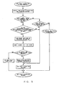
- the software module 22 compares the average signal value V 1 to the average signal value V 2 . If a difference Z between the average signal value V 1 and the average signal value V 2 exceeds a predetermined threshold, the software module 22 increases a value of the digital counter 25 ( Figure 1 ). If the difference is below the predetermined threshold, the software module 22 decreases the value of the digital counter 25.
- a minimum current qualifier can be included to prevent nuisance DC arc fault series protection due to very small currents.
- the magnitudes of the values that the software module increases or decreases the digital counter 25 may be made unequal to achieve a fast charge, slow discharge integration.
- the digital counter 25 exceeding a predetermined threshold represents a series DC arc fault condition.
- the software module 22 identifies a series DC arc fault. The software module 22 then selects one of the several output actions, as described above.
- Utilizing the software module 22 to identify both parallel and series DC arc fault events provides the advantage of characterizing electrical problems within the electrical system 10. For example, parallel DC arc events often correspond to electrical problems within a wire bundle, while series DC arc events often correspond to a loose connection. This enables the software module 22 to characterize electrical problems and respond in a desired manner through one of the predefined output actions.
- the software-based methodology described is robust enough to maintain DC arc fault monitoring capability if the software becomes corrupted by single event upsets, such as bit flipping from cosmic radiation, etc., and does not passively fail as long as current is sensed.
- Figure 5 shows an example algorithm for identifying a parallel DC arc fault as described above. Although the example shows specific steps, given this description, one of ordinary skill in the art might recognize alternative steps to achieve parallel DC arc fault detection.
- Figure 6 shows an example algorithm for detecting a series DC arc fault. Although a specific algorithm is shown, given this description, one of ordinary skill in the art might recognize alternative steps to achieve series DC arc fault detection.
Landscapes
- Emergency Protection Circuit Devices (AREA)
- Testing Of Short-Circuits, Discontinuities, Leakage, Or Incorrect Line Connections (AREA)
Claims (5)
- Procédé de détection d'un événement d'arc de courant continu DC parallèle comprenant l'étape suivante :(a) acquérir un signal (30) représentant un courant électrique continu DC sur une période de temps (X), caractérisée par les étapes suivantes :(b) déterminer une première valeur de signal basée sur une valeur de signal maximale (32) du signal acquis (30) pendant la période de temps ;(c) déterminer une seconde valeur de signal basée sur une valeur de signal minimale (34) du signal acquis (30) pendant la période de temps ;(d) déterminer une différence entre la première valeur de signal (32) et la seconde valeur de signal (34) ; et(e) comparer la différence à une valeur de signal seuil prédéterminée pour définir l'événement d'arc de courant continu DC.
- Procédé tel que décrit dans la revendication 1, comprenant (f) de commander un commutateur à semi-conducteur (20) pour qu'il s'ouvre en réponse à la définition de l'événement d'arc de courant continu DC dans l'étape (d).
- Procédé tel que décrit dans la revendication 1 ou la revendication 2, comprenant (g) de commander un commutateur à semi-conducteur (20) pour qu'il passe dans un état ouvert en réponse à la définition de plusieurs événements d'arc de courant continu DC dans l'étape (d).
- Procédé tel que décrit dans l'une quelconque des revendications précédentes, comprenant (h) de maintenir un commutateur à semi-conducteur (20) dans un état fermé et de fournir une indication de l'événement d'arc de courant continu DC en réponse à la définition de l'événement d'arc de courant continu DC ou des événements d'arc de courant continu DC dans ladite étape (e).
- Dispositif de détection d'arcs de courant continu DC parallèle comprenant :un commutateur à semi-conducteur (20) qui transmet de manière sélective une puissance électrique de courant continu ; etun module logiciel (22) qui acquiert un signal (30) représentant ledit courant continu sur une période de temps sélectionnée (X),caractérisé en ce que :le module logiciel (22) détermine des valeurs de signal maximale et minimale (32, 34) du signal (30) sur la période de temps (X), et ledit module logiciel (22) commande ledit commutateur à semi-conducteur (20) pour qu'il passe dans un état ouvert sur la base d'une comparaison entre une valeur de signal seuil prédéterminée et une différence entre une première valeur, basée sur ladite valeur de signal maximale (32), et une seconde valeur, basée sur ladite valeur de signal minimale (34).
Priority Applications (1)
| Application Number | Priority Date | Filing Date | Title |
|---|---|---|---|
| EP12165592.2A EP2482409B1 (fr) | 2005-12-09 | 2006-12-05 | Détection et protection d'un arc de défaut à courant continu |
Applications Claiming Priority (1)
| Application Number | Priority Date | Filing Date | Title |
|---|---|---|---|
| US11/298,438 US8659856B2 (en) | 2005-12-09 | 2005-12-09 | DC arc fault detection and protection |
Related Child Applications (2)
| Application Number | Title | Priority Date | Filing Date |
|---|---|---|---|
| EP12165592.2A Division EP2482409B1 (fr) | 2005-12-09 | 2006-12-05 | Détection et protection d'un arc de défaut à courant continu |
| EP12165592.2 Division-Into | 2012-04-25 |
Publications (3)
| Publication Number | Publication Date |
|---|---|
| EP1796238A2 EP1796238A2 (fr) | 2007-06-13 |
| EP1796238A3 EP1796238A3 (fr) | 2010-09-01 |
| EP1796238B1 true EP1796238B1 (fr) | 2013-01-23 |
Family
ID=37831658
Family Applications (2)
| Application Number | Title | Priority Date | Filing Date |
|---|---|---|---|
| EP12165592.2A Ceased EP2482409B1 (fr) | 2005-12-09 | 2006-12-05 | Détection et protection d'un arc de défaut à courant continu |
| EP06256200A Ceased EP1796238B1 (fr) | 2005-12-09 | 2006-12-05 | Détection et protection d'un arc de défaut à courant continu |
Family Applications Before (1)
| Application Number | Title | Priority Date | Filing Date |
|---|---|---|---|
| EP12165592.2A Ceased EP2482409B1 (fr) | 2005-12-09 | 2006-12-05 | Détection et protection d'un arc de défaut à courant continu |
Country Status (2)
| Country | Link |
|---|---|
| US (1) | US8659856B2 (fr) |
| EP (2) | EP2482409B1 (fr) |
Cited By (4)
| Publication number | Priority date | Publication date | Assignee | Title |
|---|---|---|---|---|
| US8570017B2 (en) | 2007-02-20 | 2013-10-29 | Commissariat A L'energie Atomique | Voltage limiter and protection of a photovoltaic module |
| US9746528B2 (en) | 2011-07-04 | 2017-08-29 | Commissariat à l'énergie atomique et aux énergies alternatives | Detection of electrical arcs in photovoltaic equipment |
| US9843288B2 (en) | 2013-08-29 | 2017-12-12 | Commissariat à l'énergie atomique et aux énergies alternatives | Parallel electric arc detection across the main terminals of a photovoltaic installation |
| US10432139B2 (en) | 2013-08-29 | 2019-10-01 | Commissariat à l'énergie atomique et aux énergies alternatives | Electric arc detection in photovoltaic installations |
Families Citing this family (13)
| Publication number | Priority date | Publication date | Assignee | Title |
|---|---|---|---|---|
| US8022711B2 (en) * | 2008-12-17 | 2011-09-20 | Hamilton Sundstrand Corporation | Wire fault locating in distributed power systems |
| US7872839B2 (en) * | 2009-05-12 | 2011-01-18 | Astronics Advanced Electronic Systems Corp. | Systems, methods, and devices for controlling a serial arc fault in an electrical circuit |
| EP2457313B1 (fr) * | 2009-07-23 | 2014-03-05 | Enphase Energy, Inc. | Procédé et appareil de détection d arcs électriques |
| AT509251A1 (de) | 2009-08-14 | 2011-07-15 | Fronius Int Gmbh | 4erfahren zur lichtbogendetektion in photovoltaikanlagen und eine solche photovoltaikanlage |
| US8320090B2 (en) | 2010-06-08 | 2012-11-27 | Hamilton Sundstrand Corporation | SSPC for parallel arc fault detection in DC power system |
| US8749933B2 (en) | 2010-06-14 | 2014-06-10 | Abb Research Ltd | Fault protection of HVDC transmission lines |
| US20120072739A1 (en) * | 2010-09-22 | 2012-03-22 | Michael Isaacson | Short circuit control for high current pulse power supply |
| US8909981B2 (en) | 2011-06-21 | 2014-12-09 | Hamilton Sundstrand Corporation | Control system software execution during fault detection |
| CN103336223A (zh) * | 2013-06-14 | 2013-10-02 | 上海叠泉信息科技有限公司 | 故障电弧检测与定位系统和方法 |
| DE102017101452A1 (de) | 2017-01-25 | 2018-07-26 | Eaton Industries (Austria) Gmbh | Niederspannungs-Schutzschaltgerät |
| DK3723218T3 (da) * | 2017-12-29 | 2022-01-31 | Huawei Tech Co Ltd | Metode og anordning til håndtering af jævnstrømsbue |
| US11209494B2 (en) * | 2020-01-07 | 2021-12-28 | Hamilton Sundstrand Corporation | Fault monitoring systems for power supplies |
| CN111965452A (zh) * | 2020-08-13 | 2020-11-20 | 国网福建省电力有限公司检修分公司 | 实际工况下的电弧测试系统 |
Family Cites Families (13)
| Publication number | Priority date | Publication date | Assignee | Title |
|---|---|---|---|---|
| US4466071A (en) | 1981-09-28 | 1984-08-14 | Texas A&M University System | High impedance fault detection apparatus and method |
| US5138513A (en) * | 1991-01-23 | 1992-08-11 | Ransburg Corporation | Arc preventing electrostatic power supply |
| JP3869929B2 (ja) * | 1997-03-04 | 2007-01-17 | キヤノン株式会社 | 画像形成装置 |
| DE19848636C2 (de) | 1998-10-22 | 2001-07-26 | Fraunhofer Ges Forschung | Verfahren zur Überwachung einer Wechselspannungs-Entladung an einer Doppelelektrode |
| IL135120A0 (en) | 2000-03-16 | 2001-05-20 | Sapir Michael | Apparatus for the detection and early warning of electrical arcing fault |
| US6522509B1 (en) * | 2000-07-21 | 2003-02-18 | Eaton Corporation | Arc fault detection in ac electric power systems |
| CA2369429C (fr) | 2001-01-25 | 2011-11-15 | Matsushita Electric Works, Ltd. | Methode de discrimination de courant anormal, y compris le courant d'arc, dans des circuits de charge a courant alternatif, et appareil de mise en application connexe |
| WO2003030157A1 (fr) * | 2001-09-27 | 2003-04-10 | Matsushita Electric Industrial Co., Ltd. | Lecteur de disques optiques |
| US20040027749A1 (en) * | 2001-11-09 | 2004-02-12 | Zuercher Joseph C. | Detection of arcing in dc electrical systems |
| KR20040062995A (ko) * | 2001-12-19 | 2004-07-09 | 코닌클리케 필립스 일렉트로닉스 엔.브이. | 정보를 판독하는 광학장치와 질량 불균형을 판정하는 방법 |
| US7177125B2 (en) | 2003-02-12 | 2007-02-13 | Honeywell International Inc. | Arc fault detection for SSPC based electrical power distribution systems |
| DE10319456A1 (de) | 2003-04-29 | 2004-11-18 | Siemens Ag | Schaltungsanordnung für Fahrzeug-Anwendungen |
| US7016172B2 (en) * | 2003-12-20 | 2006-03-21 | Lear Corporation | Method of detecting an arc and protecting the load against said arc |
-
2005
- 2005-12-09 US US11/298,438 patent/US8659856B2/en not_active Expired - Fee Related
-
2006
- 2006-12-05 EP EP12165592.2A patent/EP2482409B1/fr not_active Ceased
- 2006-12-05 EP EP06256200A patent/EP1796238B1/fr not_active Ceased
Cited By (4)
| Publication number | Priority date | Publication date | Assignee | Title |
|---|---|---|---|---|
| US8570017B2 (en) | 2007-02-20 | 2013-10-29 | Commissariat A L'energie Atomique | Voltage limiter and protection of a photovoltaic module |
| US9746528B2 (en) | 2011-07-04 | 2017-08-29 | Commissariat à l'énergie atomique et aux énergies alternatives | Detection of electrical arcs in photovoltaic equipment |
| US9843288B2 (en) | 2013-08-29 | 2017-12-12 | Commissariat à l'énergie atomique et aux énergies alternatives | Parallel electric arc detection across the main terminals of a photovoltaic installation |
| US10432139B2 (en) | 2013-08-29 | 2019-10-01 | Commissariat à l'énergie atomique et aux énergies alternatives | Electric arc detection in photovoltaic installations |
Also Published As
| Publication number | Publication date |
|---|---|
| EP2482409A3 (fr) | 2013-08-07 |
| US8659856B2 (en) | 2014-02-25 |
| EP2482409B1 (fr) | 2018-02-07 |
| EP2482409A2 (fr) | 2012-08-01 |
| EP1796238A2 (fr) | 2007-06-13 |
| EP1796238A3 (fr) | 2010-09-01 |
| US20070133135A1 (en) | 2007-06-14 |
Similar Documents
| Publication | Publication Date | Title |
|---|---|---|
| US7796366B2 (en) | AC arc fault detection and protection | |
| EP1796238B1 (fr) | Détection et protection d'un arc de défaut à courant continu | |
| EP2053716B1 (fr) | Procédé de détection de défaut d'arc en série de courant alternatif | |
| US10079483B2 (en) | Assembly for electrically protecting a potential short-circuit or an overload in a direct current power network having a system-determined, variable source-internal resistance | |
| EP1595320B1 (fr) | Detection de defauts d'arc pour systemes de distribution d'electricite bases sur des controleurs de puissance a semi-conducteurs | |
| US8947843B2 (en) | Fast breaker failure detection for HVDC circuit breakers | |
| WO2019183851A1 (fr) | Appareil et procédé de diagnostic de défaillance pour disjoncteur | |
| CN119093589A (zh) | 一种智能一体化电源系统的多级保护技术 | |
| KR20180115239A (ko) | 안전 모니터링 유닛 | |
| EP2477292B1 (fr) | Système de discrimination de la réinitialisation automatique et procédé pour dispositif de protection électronique autoalimenté | |
| US20090257156A1 (en) | Method of setting a ground fault trip function for a trip unit and a trip unit having a defined trip function for ground fault protection | |
| CN113098024A (zh) | 电容器系统,操作系统的方法及功率因数校正电路 | |
| JP6509029B2 (ja) | 分電盤 | |
| JP7723903B2 (ja) | 遮断制御装置 | |
| EP4081814B1 (fr) | Modules de détection de défaut d'arc pour systèmes électriques de véhicule | |
| JP7839830B2 (ja) | 動力電池及びその制御システム並びに制御方法 | |
| US20260018358A1 (en) | Active arc fault circuit interrupters with solid-state components | |
| EP4672529A1 (fr) | Procédé de coordination de protection pour microréseaux cc | |
| CN113905497A (zh) | 一种智慧照明的自动保护系统及方法 | |
| KR20090109494A (ko) | 접지 장애 트립 함수 설정 방법 |
Legal Events
| Date | Code | Title | Description |
|---|---|---|---|
| PUAI | Public reference made under article 153(3) epc to a published international application that has entered the european phase |
Free format text: ORIGINAL CODE: 0009012 |
|
| AK | Designated contracting states |
Kind code of ref document: A2 Designated state(s): AT BE BG CH CY CZ DE DK EE ES FI FR GB GR HU IE IS IT LI LT LU LV MC NL PL PT RO SE SI SK TR |
|
| AX | Request for extension of the european patent |
Extension state: AL BA HR MK YU |
|
| RTI1 | Title (correction) |
Free format text: DC ARC FAULT DETECTION AND PROTECTION |
|
| PUAL | Search report despatched |
Free format text: ORIGINAL CODE: 0009013 |
|
| AK | Designated contracting states |
Kind code of ref document: A3 Designated state(s): AT BE BG CH CY CZ DE DK EE ES FI FR GB GR HU IE IS IT LI LT LU LV MC NL PL PT RO SE SI SK TR |
|
| AX | Request for extension of the european patent |
Extension state: AL BA HR MK RS |
|
| 17P | Request for examination filed |
Effective date: 20110301 |
|
| AKX | Designation fees paid |
Designated state(s): DE FR GB |
|
| GRAP | Despatch of communication of intention to grant a patent |
Free format text: ORIGINAL CODE: EPIDOSNIGR1 |
|
| GRAS | Grant fee paid |
Free format text: ORIGINAL CODE: EPIDOSNIGR3 |
|
| GRAA | (expected) grant |
Free format text: ORIGINAL CODE: 0009210 |
|
| AK | Designated contracting states |
Kind code of ref document: B1 Designated state(s): DE FR GB |
|
| REG | Reference to a national code |
Ref country code: GB Ref legal event code: FG4D |
|
| REG | Reference to a national code |
Ref country code: DE Ref legal event code: R096 Ref document number: 602006034343 Country of ref document: DE Effective date: 20130321 |
|
| PLBE | No opposition filed within time limit |
Free format text: ORIGINAL CODE: 0009261 |
|
| STAA | Information on the status of an ep patent application or granted ep patent |
Free format text: STATUS: NO OPPOSITION FILED WITHIN TIME LIMIT |
|
| 26N | No opposition filed |
Effective date: 20131024 |
|
| REG | Reference to a national code |
Ref country code: DE Ref legal event code: R097 Ref document number: 602006034343 Country of ref document: DE Effective date: 20131024 |
|
| REG | Reference to a national code |
Ref country code: FR Ref legal event code: PLFP Year of fee payment: 10 |
|
| REG | Reference to a national code |
Ref country code: FR Ref legal event code: PLFP Year of fee payment: 11 |
|
| REG | Reference to a national code |
Ref country code: DE Ref legal event code: R082 Ref document number: 602006034343 Country of ref document: DE Representative=s name: SCHMITT-NILSON SCHRAUD WAIBEL WOHLFROM PATENTA, DE |
|
| REG | Reference to a national code |
Ref country code: FR Ref legal event code: PLFP Year of fee payment: 12 |
|
| P01 | Opt-out of the competence of the unified patent court (upc) registered |
Effective date: 20230522 |
|
| PGFP | Annual fee paid to national office [announced via postgrant information from national office to epo] |
Ref country code: GB Payment date: 20231121 Year of fee payment: 18 |
|
| PGFP | Annual fee paid to national office [announced via postgrant information from national office to epo] |
Ref country code: FR Payment date: 20231122 Year of fee payment: 18 Ref country code: DE Payment date: 20231121 Year of fee payment: 18 |
|
| REG | Reference to a national code |
Ref country code: DE Ref legal event code: R119 Ref document number: 602006034343 Country of ref document: DE |
|
| GBPC | Gb: european patent ceased through non-payment of renewal fee |
Effective date: 20241205 |
|
| PG25 | Lapsed in a contracting state [announced via postgrant information from national office to epo] |
Ref country code: DE Free format text: LAPSE BECAUSE OF NON-PAYMENT OF DUE FEES Effective date: 20250701 |
|
| PG25 | Lapsed in a contracting state [announced via postgrant information from national office to epo] |
Ref country code: GB Free format text: LAPSE BECAUSE OF NON-PAYMENT OF DUE FEES Effective date: 20241205 |
|
| PG25 | Lapsed in a contracting state [announced via postgrant information from national office to epo] |
Ref country code: FR Free format text: LAPSE BECAUSE OF NON-PAYMENT OF DUE FEES Effective date: 20241231 |