EP1796259A2 - System und Verfahren zum Betreiben von doppelt gespeisten Induktionsgeneratoren - Google Patents
System und Verfahren zum Betreiben von doppelt gespeisten Induktionsgeneratoren Download PDFInfo
- Publication number
- EP1796259A2 EP1796259A2 EP06125643A EP06125643A EP1796259A2 EP 1796259 A2 EP1796259 A2 EP 1796259A2 EP 06125643 A EP06125643 A EP 06125643A EP 06125643 A EP06125643 A EP 06125643A EP 1796259 A2 EP1796259 A2 EP 1796259A2
- Authority
- EP
- European Patent Office
- Prior art keywords
- impedance
- utility grid
- current
- grid
- protection system
- Prior art date
- Legal status (The legal status is an assumption and is not a legal conclusion. Google has not performed a legal analysis and makes no representation as to the accuracy of the status listed.)
- Granted
Links
Images



Classifications
-
- H—ELECTRICITY
- H02—GENERATION; CONVERSION OR DISTRIBUTION OF ELECTRIC POWER
- H02P—CONTROL OR REGULATION OF ELECTRIC MOTORS, ELECTRIC GENERATORS OR DYNAMO-ELECTRIC CONVERTERS; CONTROLLING TRANSFORMERS, REACTORS OR CHOKE COILS
- H02P9/00—Arrangements for controlling electric generators for the purpose of obtaining a desired output
- H02P9/007—Control circuits for doubly fed generators
-
- H—ELECTRICITY
- H02—GENERATION; CONVERSION OR DISTRIBUTION OF ELECTRIC POWER
- H02P—CONTROL OR REGULATION OF ELECTRIC MOTORS, ELECTRIC GENERATORS OR DYNAMO-ELECTRIC CONVERTERS; CONTROLLING TRANSFORMERS, REACTORS OR CHOKE COILS
- H02P9/00—Arrangements for controlling electric generators for the purpose of obtaining a desired output
- H02P9/006—Means for protecting the generator by using control
-
- H—ELECTRICITY
- H02—GENERATION; CONVERSION OR DISTRIBUTION OF ELECTRIC POWER
- H02P—CONTROL OR REGULATION OF ELECTRIC MOTORS, ELECTRIC GENERATORS OR DYNAMO-ELECTRIC CONVERTERS; CONTROLLING TRANSFORMERS, REACTORS OR CHOKE COILS
- H02P9/00—Arrangements for controlling electric generators for the purpose of obtaining a desired output
- H02P9/10—Control effected upon generator excitation circuit to reduce harmful effects of overloads or transients, e.g. sudden application of load, sudden removal of load, sudden change of load
-
- H—ELECTRICITY
- H02—GENERATION; CONVERSION OR DISTRIBUTION OF ELECTRIC POWER
- H02P—CONTROL OR REGULATION OF ELECTRIC MOTORS, ELECTRIC GENERATORS OR DYNAMO-ELECTRIC CONVERTERS; CONTROLLING TRANSFORMERS, REACTORS OR CHOKE COILS
- H02P2101/00—Special adaptation of control arrangements for generators
- H02P2101/15—Special adaptation of control arrangements for generators for wind-driven turbines
Definitions
- the present invention relates generally to the field of double fed induction generators.
- the present invention relates to control and protection of double fed induction generators during grid faults.
- Double fed induction generators are used in a wide range of applications because of their efficiency and reliability.
- DFIGs are used in variable speed generation (VSG) systems for generating electric energy from intermittent or variable energy resources such as wind farms.
- VSG variable speed generation
- the main advantage of a variable speed generation system over a fixed speed system is the possibility of electronically controlling the shaft speed in order to maintain maximum efficiency of the energy conversion process.
- a wind turbine generator typically uses a DFIG comprising an AC/DC converter coupled to a DC/AC converter for wind power generation.
- the DFIG technology enables maximum energy to be extracted from the wind for low wind speeds by optimizing the turbine speed, while minimizing mechanical stresses on the turbine during gusts of wind and grid transients.
- Another advantage of the DFIG technology is the ability for power electronic converters to generate or absorb reactive power, thus reducing the need for installing capacitor banks.
- DFIG controller design considerations have generally concentrated on providing an adjustable operating speed to maximize turbine power output, maintaining the required generator terminal voltage or power factor, and controlling the generator torque to match that of the wind turbine.
- little or no attempt has been made to provide the capability of contributing to stability of power network operation.
- the increasingly widespread use of wind power generation requires the wind-farms to contribute to the stability of power network operation.
- Wind turbines with double fed induction generators are sensitive to grid faults.
- a grid fault will give rise to severe transients in the air-gap torque and shaft torque and may therefore impact system reliability. For example, when grid voltage drops below a threshold value due to a grid fault, the air-gap torque also drops, thereby leading to an oscillation in the gearbox and drive shaft that may reduce gearbox life.
- Grid recovery sequences also result in severe transient conditions in double fed induction generators.
- a conventional technique to avoid damage in the DFIG and the gearbox includes disconnecting the wind turbine generators from the grid when large voltage sags appear in the grid due to grid fault. After a period of time, the turbine is then reconnected to the grid.
- new grid codes now require wind turbines and wind farms to ride through voltage sags, meaning that normal power production should be immediately re-established once the nominal grid voltage has recovered.
- anti-parallel thyristors may be used in the stator circuit to achieve a quick (within 10 milliseconds, for example) disconnection of the stator circuit, and also provide the capability to remagnetize the generator and reconnect the stator to the grid as fast as possible.
- Another option proposed is to use a static switch in the rotor circuit, which can break the short circuit current in the rotor.
- a third method is to use a DVR (Dynamic Voltage Restorer) that can isolate the DFIG system from voltage sags.
- DVR Dynamic Voltage Restorer
- a protection system includes a plurality of controlled impedance devices. Each of the controlled impedance devices is coupled between a respective phase of a stator winding of a double fed induction generator and a respective phase of a grid side converter.
- the protection system also includes a controller configured for coupling and decoupling impedance in one or more of the plurality of controlled impedance devices in response to changes in at least one of a utility grid voltage and a utility grid current.
- a wind turbine generator in accordance with another aspect of the present invention, includes a wind turbine coupled to a double fed induction generator and a plurality of controlled impedance devices. Each of the controlled impedance devices is coupled between a respective phase of a stator winding of the double fed induction generator and a respective phase of a grid side converter.
- the wind turbine generator also includes a controller configured for coupling and decoupling impedance in one or more of the plurality of controlled impedance devices in response to changes in at least one of a utility grid voltage and a utility grid current.
- a protection method is provided.
- the protection method provides for coupling and decoupling impedance in one or more of a plurality of controlled impedance devices in response to changes in at least one of a utility grid voltage and a utility grid current.
- Each of the controlled impedance devices is coupled between a respective phase of a stator winding of a double fed induction generator and a respective phase of a grid side converter.
- Embodiments of the present invention are generally directed to control and protection of double fed induction generators (DFIGs) and gearboxes during grid faults. Such embodiments may be used in a variety of applications, such as for wind power generation, variable speed hydraulic generation and so forth. Though the present discussion provides examples in a wind power generation context, one of ordinary skill in the art will readily apprehend that the application of these embodiments in other contexts is well within the scope of the present invention.
- DFIGs double fed induction generators
- the wind turbine generator 10 is coupled to a utility grid 12 for electrical power distribution and includes a wind turbine 14 coupled to a DFIG 16.
- the DFIG 16 comprises a stator 18 and a rotor 20.
- the rotor 20 is mechanically coupled to the wind turbine shaft 22 via a gearbox 24.
- the stator windings of the DFIG 16 are coupled to the utility grid 12 via a protection system 30, and the rotor windings of the DFIG 16 are coupled to the utility grid 12 via a back-to-back converter 26 and an electrical filter 28.
- the protection system 30 is provided between the stator 18 and the grid side of the back-to-back converter 26 in accordance with aspects of the present invention for protecting the DFIG 16 and the gearbox 24 during transient conditions.
- the protection system 30 may include a controller 32 for controlling the protection system 30 based on the changes in at least one of grid voltage and grid current.
- the back-to-back converter 26 further includes a grid side AC-DC converter (rectifier) 34 and a machine side DC-AC converter (inverter) 36 that are coupled to each other in a back-to-back configuration. Between the two converters 34 and 36 a DC link capacitor 38 may be provided as an energy storage device for keeping the voltage variation (ripples) in the DC link voltage small.
- the grid-side converter 34 provides a constant DC-link voltage while the machine-side converter 36 enables the control of the torque or the speed of the DFIG 16 and also the power factor at the stator terminals.
- the electrical filter 28 prevents or reduces harmonics generated by the back-to-back converter 26 from being injected into the utility grid 12.
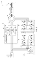
- the wind turbine generator 10 is illustrated in greater detail in FIG. 2.
- the electrical filter 28 may comprise an AC filter and more specifically may comprise an LC filter coupled to the utility grid 12 and tuned for preventing or reducing harmonics generated by the back-to-back converter 26 from being injected into the utility grid 12.
- each of the converters 34 and 36 includes six power switching devices 40 connected in a bridge configuration. Each of the power switching devices 40 may be provided with a free-wheeling diode 42.
- Switching devices 40 may be gate controllable active switches such as GTOs, BJTs, IGBTs, or any other gate controllable active switches.
- a converter controller (not shown) may be provided to control the operation of each of the gate controllable active switches 40. In one embodiment, the controller controls current on the rotor windings so that desired values of active and reactive power delivered by the generator stator windings may be obtained. If desired, the converter controller and the protection system controller 32 may be integrated into a single control unit.
- the protection system 30 comprises a controlled impedance device 44 coupled between each phase of the stator winding of the double fed induction generator 16 and a corresponding phase of the grid side converter 34.
- Each of the controlled impedance devices 44 includes an impedance device 46.
- the impedance device 46 is positioned in parallel with a semiconductor device 48.
- the semiconductor device 48 is configured to couple or decouple the impedance device 46 from each phase in response to changes in at least one of measured voltage and measured current of the utility grid 12 based on control signals received from the controller 32.
- the semiconductor device 48 may be a bidirectional semiconductor device such as a triac, an assembly of thyristors, or anti-parallel thyristors.
- the semiconductor device 48 is ON and hence offers a very low resistance to the stator current in comparison to the resistance offered by the impedance device 46.
- Each phase of the stator winding is therefore connected to the utility grid 12 via the semiconductor device 48 while the impedance device 46 is bypassed.
- the semiconductor device 48 is switched OFF and hence offers a very high resistance to the stator current in comparison to the resistance offered by the impedance device 46.
- Each phase of the stator winding is therefore connected to the utility grid 12 via the impedance device 46 while the semiconductor device 48 is OFF.
- the stator current therefore flows via the impedance device 46, which is coupled in the circuit during grid faults.
- the controller 32 may monitor at least one of grid voltage and grid current via one or more sensors (not shown). When the grid voltage drops below a certain first threshold value (0.6 per unit, for example), or the grid current rises above a certain first threshold value, the circuit will switch to low-voltage mode of operation, and the controller 32 will switch off the semiconductor device 48 to couple the impedance device 46 in one or more phase.
- the switched impedance device 46 between one or more phases of the stator winding and the grid side converter 34 increases the stator voltage.
- the stator current may therefore be regulated so that the air-gap torque follows torque command.
- the stator voltage may be regulated in phase with grid voltage to provide unity power factor, or may be regulated to provide reactive power to the grid. Further, when the grid voltage rises above a certain second threshold value (0.65 per unit, for example), or the grid current drops below a certain second threshold value, the controller 32 will switch on the semiconductor device 48 to decouple the impedance device 46 in one or more phases, and return to normal mode of operation. It should be noted that, in certain embodiments, the first and the second threshold value may be same. Further, it should be noted that, the first and the second threshold value may be predetermined or may be decided dynamically.
- the impedance device 46 may be properly designed and predetermined to have a fixed impedance value, so that the air-gap torque may be maintained when the grid voltage is between zero and the threshold, while limiting the stator over-current.
- a variable impedance device may be employed so that the impedance device 46 is varied during operation based upon the transient conditions.
- FIG. 3 depicts a simulation of grid voltage waveforms 50, stator voltage waveform 52, air-gap torque waveform 54, rotor current waveform 56, stator current waveform 58, and the trigger signal 60 for the semiconductor device for the wind turbine generator of FIG. 2 in accordance with aspects of the present invention.
- the controller 32 switches OFF the semiconductor device 48 via the trigger signal.
- the impedance device 46 is therefore coupled into the circuit to protect the DFIG 16, the gearbox 24, and the wind turbine 14 from transients.
- the stator voltage 52 increases and is in phase with the grid voltage during the transient.
- the air-gap torque is controlled to be within a normal value.
- the stator and rotor current is controlled to be within a normal value.
- the controlled impedance device 44 may include a current dependent variable impedance device 62, such as a variable resistor, PTC thermistor and so forth, as illustrated in FIG. 4.
- a variable impedance device is a device with a significant non-linear current-voltage characteristic and is used to protect circuits against excessive transient currents.
- the current dependent variable impedance device 62 may be coupled between each phase of the stator winding of the double fed induction generator 16 and a corresponding phase of the grid side converter 34.
- the variable impedance device 62 is configured to offer varying impedances depending on the stator current.
- variable impedance device 62 offers very low impedance when the flowing stator current is below a threshold or a rated current (corresponding to normal operation). However, the variable impedance device 62 offers higher impedance when the flowing stator current is above a threshold or above rated current (corresponding to low grid voltage condition during grid faults). Thus, the variable impedance device 62 functions by automatically coupling and decoupling impedance based on the flowing stator current.
- the control and protection embodiments discussed above provide contribution to network operation and stability under large and small disturbances (transient conditions).
- the impedance limits the air gap torque to normal values, limits the stator and rotor over-current, and reduces the oscillation in gearbox during grid faults.
- the stator over-current may be limited to 1.6 per unit, for example, when regulating the air-gap torque to nominal.
- the impedance reduces the transient caused by grid recovery.
- the technique described in the various embodiments discussed above may also be applied in variable speed hydraulic generator.
Landscapes
- Engineering & Computer Science (AREA)
- Power Engineering (AREA)
- Control Of Eletrric Generators (AREA)
Applications Claiming Priority (1)
| Application Number | Priority Date | Filing Date | Title |
|---|---|---|---|
| US11/297,775 US7253537B2 (en) | 2005-12-08 | 2005-12-08 | System and method of operating double fed induction generators |
Publications (3)
| Publication Number | Publication Date |
|---|---|
| EP1796259A2 true EP1796259A2 (de) | 2007-06-13 |
| EP1796259A3 EP1796259A3 (de) | 2015-09-23 |
| EP1796259B1 EP1796259B1 (de) | 2017-09-13 |
Family
ID=37903482
Family Applications (1)
| Application Number | Title | Priority Date | Filing Date |
|---|---|---|---|
| EP06125643.4A Active EP1796259B1 (de) | 2005-12-08 | 2006-12-07 | System zum Betreiben von doppelt gespeisten Induktionsgeneratoren |
Country Status (5)
| Country | Link |
|---|---|
| US (1) | US7253537B2 (de) |
| EP (1) | EP1796259B1 (de) |
| CN (1) | CN101005204B (de) |
| DK (1) | DK1796259T3 (de) |
| ES (1) | ES2644691T3 (de) |
Cited By (9)
| Publication number | Priority date | Publication date | Assignee | Title |
|---|---|---|---|---|
| EP2306625A2 (de) * | 2009-09-30 | 2011-04-06 | General Electric Company | Verfahren und Vorrichtung zur Erzeugung von Energie in einer Windturbine |
| WO2010057762A3 (de) * | 2008-11-19 | 2011-07-21 | Woodward Kempen Gmbh | Vorrichtung zur regelung einer doppelt gespeisten asynchronmaschine |
| EP2461026A1 (de) * | 2010-12-03 | 2012-06-06 | Siemens Aktiengesellschaft | Anordnung und Verfahren zum Prüfen eines Stromerzeugungssystems |
| EP2461027A1 (de) * | 2010-12-03 | 2012-06-06 | Siemens Aktiengesellschaft | Anordnung und Verfahren zum Prüfen eines Stromerzeugungssystems |
| CN103311903A (zh) * | 2012-03-08 | 2013-09-18 | 台达电子工业股份有限公司 | 一种开关装置及其发电系统 |
| US8973814B2 (en) | 2010-08-16 | 2015-03-10 | Siemens Aktiengesellschaft | Method for the verifiable delivery of an article |
| EP2161443A3 (de) * | 2008-09-08 | 2015-06-24 | General Electric Company | Windturbine mit Hauptstromwandler und Hilfsstromwandler und Steuerungsverfahren dafür |
| EP2744099A4 (de) * | 2011-08-11 | 2016-07-13 | Shunxin Zhou | Steuersystem zur durchführung einer eingangsleistungsänderung entlang zweier lasten und zur erzeugung einer drehgeschwindigkeit durch eine wechselrichterbrücke zum ziehen vieler sätze von motoren |
| CN112564121A (zh) * | 2020-12-09 | 2021-03-26 | 湖南大学 | 面向拓扑重构与功能复用的串联型电力电子设备及控制方法 |
Families Citing this family (65)
| Publication number | Priority date | Publication date | Assignee | Title |
|---|---|---|---|---|
| WO2004098261A2 (en) | 2003-05-02 | 2004-11-18 | Xantrex Technology Inc. | Control system for doubly fed induction generator |
| DK1752660T3 (da) * | 2005-08-12 | 2013-06-17 | Gen Electric | Beskyttelsesindretning mod overspænding til en vindmølle |
| EP1770277A1 (de) * | 2005-09-30 | 2007-04-04 | General Electric Company | Verfahren zur Regelung einer Windenergieanlage eines Windparks |
| KR100668118B1 (ko) * | 2005-12-30 | 2007-01-16 | 한국전기연구원 | 권선형 유도 발전기 제어용 전력변환장치 및 전력변환방법 |
| EP2032846A4 (de) * | 2006-05-31 | 2011-04-13 | Wisconsin Alumni Res Found | Aufbereitungsarchitektur für eine windturbine |
| US7629705B2 (en) * | 2006-10-20 | 2009-12-08 | General Electric Company | Method and apparatus for operating electrical machines |
| WO2008131776A2 (en) * | 2007-04-30 | 2008-11-06 | Vestas Wind Systems A/S | A method of operating a wind turbine, a wind turbine and a cluster of wind turbines |
| GB2449119B (en) * | 2007-05-11 | 2012-02-29 | Converteam Technology Ltd | Power converters |
| US8513911B2 (en) | 2007-05-11 | 2013-08-20 | Converteam Technology Ltd. | Power converters |
| US7877170B2 (en) * | 2007-05-24 | 2011-01-25 | Verdant Power | Remanent voltage generator tachometer and control for induction machine |
| JP2008306776A (ja) * | 2007-06-05 | 2008-12-18 | Hitachi Ltd | 風力発電システムおよびその制御方法 |
| KR100886194B1 (ko) * | 2007-06-08 | 2009-02-27 | 한국전기연구원 | 계통 연계형 고압 권선형 유도 발전기 제어 장치 |
| US7852643B2 (en) * | 2007-06-27 | 2010-12-14 | General Electric Company | Cross current control for power converter system |
| ES2355660T3 (es) * | 2007-07-16 | 2011-03-29 | GAMESA INNOVATION & TECHNOLOGY, S.L. | Sistema de energía eólica y procedimiento para hacerlo funcionar. |
| US8097980B2 (en) * | 2007-09-24 | 2012-01-17 | Sunlight Photonics Inc. | Distributed solar power plant and a method of its connection to the existing power grid |
| DE102008009279A1 (de) * | 2008-02-15 | 2009-08-27 | Converteam Technology Ltd., Rugby | Ein- oder mehrphasige elektrische Schaltung zum Abschalten eines über einen Wechselstrom- oder Drehstromsteller geführten Stroms |
| DE102008009278A1 (de) * | 2008-02-15 | 2009-08-27 | Converteam Technology Ltd., Rugby | Mehrphasige elektrische Schaltung zum Abschalten eines über jeweils einen Drehstromsteller geführten Stroms |
| DE102008026621A1 (de) * | 2008-02-15 | 2009-08-20 | Converteam Technology Ltd., Rugby | Ein- oder mehrphasige elektrische Schaltung zum Abschalten eines über einen Wechselstrom- oder Drehstromsteller geführten Stroms |
| JP4480777B2 (ja) * | 2008-06-04 | 2010-06-16 | 三菱電機株式会社 | 可変速同期発電電動機 |
| US8120932B2 (en) * | 2008-07-01 | 2012-02-21 | American Superconductor Corporation | Low voltage ride through |
| EP2161821B1 (de) * | 2008-09-03 | 2020-06-17 | General Electric Company | Magnetisch angetriebener Generator |
| US7786608B2 (en) * | 2008-11-17 | 2010-08-31 | General Electric Company | Protection system for wind turbine |
| US7804184B2 (en) * | 2009-01-23 | 2010-09-28 | General Electric Company | System and method for control of a grid connected power generating system |
| ES2378964B1 (es) * | 2009-03-02 | 2013-02-22 | Ingeteam Power Technology, S.A. | Método para operar un convertidor de un generador eólico. |
| US8655495B2 (en) * | 2009-06-24 | 2014-02-18 | Vestas Wind Systems A/S | Current control of a wind park |
| US7863766B2 (en) * | 2009-06-30 | 2011-01-04 | Teco-Westinghouse Motor Company | Power converter for use with wind generator |
| EP2299568B1 (de) * | 2009-08-21 | 2016-06-22 | Vestas Wind Systems A/S | System und Verfahren zur Überwachung von Leistungsfiltern und zur Detektion von Leistungsfilterdefekten in einem elektrischen Windturbinengenerator |
| US7888915B2 (en) * | 2009-09-11 | 2011-02-15 | General Electric Company | System for detecting generator winding faults |
| JP5128568B2 (ja) * | 2009-09-30 | 2013-01-23 | 株式会社日立製作所 | 風力発電システムおよび制御法 |
| US8018082B2 (en) * | 2009-11-25 | 2011-09-13 | General Electric Company | Method and apparatus for controlling a wind turbine |
| US8046109B2 (en) * | 2009-12-16 | 2011-10-25 | General Electric Company | Method and systems for operating a wind turbine |
| US10137542B2 (en) | 2010-01-14 | 2018-11-27 | Senvion Gmbh | Wind turbine rotor blade components and machine for making same |
| CN102762850B (zh) | 2010-01-14 | 2015-04-08 | 耐普迪考股份有限公司 | 风力涡轮机转子叶片部件及其制造方法 |
| BRPI1000029A2 (pt) * | 2010-02-18 | 2018-02-14 | Mitsubishi Heavy Industries , Ltd. | método de operação de manutenção para um gerador de turbina éolica, e, gerador de turbina eólica |
| BR112012032059A2 (pt) * | 2010-06-14 | 2016-11-08 | Ingeteam Power Technology Sa | sistema de geração elétrica resistente a assimetrias de tensão. |
| US20120147637A1 (en) | 2010-12-13 | 2012-06-14 | Northern Power Systems, Inc. | Methods, Systems, and Software for Controlling a Power Converter During Low (Zero)-Voltage Ride-Through Conditions |
| CN102055207B (zh) * | 2010-12-16 | 2012-08-01 | 南京飓能电控自动化设备制造有限公司 | 低电压穿越智能功率控制单元及其应用 |
| EP2477325B1 (de) * | 2011-01-18 | 2019-04-24 | Vestas Wind Systems A/S | Verfahren für den Betrieb eines elektromechanischen Generators |
| CN102810875B (zh) * | 2011-05-30 | 2014-10-22 | 通用电气公司 | 使用变流器进行能量转换的系统及其运作方法 |
| ITMI20111180A1 (it) * | 2011-06-28 | 2012-12-29 | Wilic Sarl | Impianto eolico per la generazione di energia elettrica |
| EP2557648A1 (de) * | 2011-08-09 | 2013-02-13 | Siemens Aktiengesellschaft | Windpark und Verfahren zum Betrieb eines Windparks |
| US9041234B2 (en) | 2012-03-26 | 2015-05-26 | Rockwell Automation Technologies, Inc. | Double fed induction generator (DFIG) converter and method for improved grid fault ridethrough |
| US8664788B1 (en) * | 2012-09-07 | 2014-03-04 | General Electric Company | Method and systems for operating a wind turbine using dynamic braking in response to a grid event |
| US9030174B2 (en) | 2012-09-14 | 2015-05-12 | General Electric Company | Current balance control in converter for doubly fed induction generator wind turbine system |
| US8872372B2 (en) | 2012-11-30 | 2014-10-28 | General Electric Company | Method and systems for operating a wind turbine when recovering from a grid contingency event |
| CN103066622B (zh) * | 2012-12-28 | 2015-06-24 | 东方电气集团东方汽轮机有限公司 | 一种新型双馈风力发电机组及其运行方式 |
| CN103105583A (zh) * | 2013-01-15 | 2013-05-15 | 南京南瑞继保电气有限公司 | 一种低电压故障快速检测方法 |
| US9343991B2 (en) * | 2013-01-18 | 2016-05-17 | General Electric Company | Current balance control for non-interleaved parallel bridge circuits in power converter |
| US8941961B2 (en) | 2013-03-14 | 2015-01-27 | Boulder Wind Power, Inc. | Methods and apparatus for protection in a multi-phase machine |
| US9614457B2 (en) | 2013-10-18 | 2017-04-04 | Abb Schweiz Ag | Modular thyristor-based rectifier circuits |
| US9334749B2 (en) | 2013-10-18 | 2016-05-10 | Abb Technology Ag | Auxiliary power system for turbine-based energy generation system |
| US9577557B2 (en) * | 2013-10-18 | 2017-02-21 | Abb Schweiz Ag | Turbine-generator system with DC output |
| WO2015092553A2 (en) * | 2013-12-18 | 2015-06-25 | Ingeteam Power Technology, S.A. | Variable impedance device for a wind turbine |
| EP2905162B1 (de) * | 2014-02-07 | 2016-09-21 | Visedo Oy | Elektromechanischer Antrieb für eine Arbeitsmaschine |
| EP2961060B1 (de) * | 2014-06-23 | 2021-06-09 | GE Energy Power Conversion Technology Ltd | Elektrisches Versorgungssystem einer Last und entsprechendes Versorgungsverfahren |
| CN105790298B (zh) * | 2014-12-23 | 2019-03-12 | 台达电子工业股份有限公司 | 风力发电控制装置及风力发电系统 |
| US9847733B2 (en) | 2016-05-12 | 2017-12-19 | Rockwell Automation Technologies, Inc. | Power conversion system with DC bus regulation for abnormal grid condition ride through |
| US10819269B2 (en) | 2016-09-09 | 2020-10-27 | Inventus Holdings, Llc | DC integration of photovoltaic and DFIG wind turbine generation with electric storage |
| US10003239B1 (en) * | 2016-12-16 | 2018-06-19 | General Electric Company | Doubly-fed induction generator system for a gas turbine |
| US20190140569A1 (en) * | 2017-11-09 | 2019-05-09 | General Electric Company | DFIG Converter Overmodulation |
| WO2019147887A1 (en) * | 2018-01-25 | 2019-08-01 | Inventus Holdings, Llc | Wind turbina with electric strorage |
| CN110080944B (zh) * | 2018-01-26 | 2021-09-24 | 通用电气公司 | 风力发电系统及其控制方法 |
| US10778112B2 (en) * | 2018-04-04 | 2020-09-15 | General Electric Company | DFIG converter with active filter |
| DK3788705T3 (da) * | 2018-05-04 | 2025-05-26 | General Electric Renovables Espana Sl | Fremgangsmåde til styring af beskyttelse af omskifter enheder i effektomformere i effektsystemer med dobbelttilført induktionsgenerator |
| CN116317742B (zh) * | 2023-05-16 | 2023-08-29 | 北京金风科创风电设备有限公司 | 风力发电机组的转矩控制装置、风力发电机组及控制方法 |
Family Cites Families (11)
| Publication number | Priority date | Publication date | Assignee | Title |
|---|---|---|---|---|
| US5986438A (en) * | 1998-04-21 | 1999-11-16 | Heller-Dejulio Corporation | Rotary induction machine having control of secondary winding impedance |
| AU2001274396A1 (en) * | 2000-05-23 | 2001-12-03 | Vestas Wind Systems A/S | Variable speed wind turbine having a matrix converter |
| JP4118531B2 (ja) * | 2001-05-10 | 2008-07-16 | 株式会社東芝 | 電力調整装置 |
| DK174755B1 (da) * | 2002-01-14 | 2003-10-20 | Vestas Wind Sys As | System til at forbinde en vindmøllegenerator med det elektriske forsyningsnet |
| JP2005516577A (ja) * | 2002-01-29 | 2005-06-02 | ヴェスタス,ウィンド,システムズ エー/エス | 風力エネルギーの設備に使用するための回路装置 |
| US7015595B2 (en) * | 2002-02-11 | 2006-03-21 | Vestas Wind Systems A/S | Variable speed wind turbine having a passive grid side rectifier with scalar power control and dependent pitch control |
| US7071579B2 (en) * | 2002-06-07 | 2006-07-04 | Global Energyconcepts,Llc | Wind farm electrical system |
| ES2392683T3 (es) | 2002-11-01 | 2012-12-12 | Vestas Wind Systems A/S | Disposición de circuito para su uso en un sistema de turbina eólica de velocidad variable que comprende un generador de inducción de doble alimentación y un convertidor reversible |
| EP1499009B1 (de) | 2003-07-15 | 2007-10-31 | Gamesa Innovation & Technology, S.L. Unipersonal | Steuer- und Schutzgerät für ein doppelgespeistes Induktionsgeneratorsystem |
| US7834472B2 (en) * | 2003-08-07 | 2010-11-16 | Vestas Wind Systems A/S | Method of controlling a wind turbine connected to an electric utility grid during malfunction in said electric utility grid, control system, wind turbine and family hereof |
| US7038329B1 (en) * | 2004-11-04 | 2006-05-02 | Utc Power, Llc | Quality power from induction generator feeding variable speed motors |
-
2005
- 2005-12-08 US US11/297,775 patent/US7253537B2/en not_active Expired - Lifetime
-
2006
- 2006-12-07 ES ES06125643.4T patent/ES2644691T3/es active Active
- 2006-12-07 DK DK06125643.4T patent/DK1796259T3/da active
- 2006-12-07 EP EP06125643.4A patent/EP1796259B1/de active Active
- 2006-12-08 CN CN2006100643247A patent/CN101005204B/zh active Active
Cited By (14)
| Publication number | Priority date | Publication date | Assignee | Title |
|---|---|---|---|---|
| EP2161443A3 (de) * | 2008-09-08 | 2015-06-24 | General Electric Company | Windturbine mit Hauptstromwandler und Hilfsstromwandler und Steuerungsverfahren dafür |
| US8653683B2 (en) | 2008-11-19 | 2014-02-18 | Woodward Kempen Gmbh | Device for controlling a double-fed asynchronous machine |
| WO2010057762A3 (de) * | 2008-11-19 | 2011-07-21 | Woodward Kempen Gmbh | Vorrichtung zur regelung einer doppelt gespeisten asynchronmaschine |
| EP2306625A2 (de) * | 2009-09-30 | 2011-04-06 | General Electric Company | Verfahren und Vorrichtung zur Erzeugung von Energie in einer Windturbine |
| US8973814B2 (en) | 2010-08-16 | 2015-03-10 | Siemens Aktiengesellschaft | Method for the verifiable delivery of an article |
| EP2461027A1 (de) * | 2010-12-03 | 2012-06-06 | Siemens Aktiengesellschaft | Anordnung und Verfahren zum Prüfen eines Stromerzeugungssystems |
| WO2012072412A1 (en) * | 2010-12-03 | 2012-06-07 | Siemens Aktiengesellschaft | Arrangement and method for testing an electric power generation system |
| EP2461026A1 (de) * | 2010-12-03 | 2012-06-06 | Siemens Aktiengesellschaft | Anordnung und Verfahren zum Prüfen eines Stromerzeugungssystems |
| EP2744099A4 (de) * | 2011-08-11 | 2016-07-13 | Shunxin Zhou | Steuersystem zur durchführung einer eingangsleistungsänderung entlang zweier lasten und zur erzeugung einer drehgeschwindigkeit durch eine wechselrichterbrücke zum ziehen vieler sätze von motoren |
| US9859822B2 (en) | 2011-08-11 | 2018-01-02 | Shunxin Zhou | Control system for realizing the change of input power with load and rotating speed simultaneously, by driving multiple electric motors via one inverter bridge |
| CN103311903A (zh) * | 2012-03-08 | 2013-09-18 | 台达电子工业股份有限公司 | 一种开关装置及其发电系统 |
| CN103311903B (zh) * | 2012-03-08 | 2016-05-04 | 台达电子工业股份有限公司 | 一种开关装置及其发电系统 |
| CN112564121A (zh) * | 2020-12-09 | 2021-03-26 | 湖南大学 | 面向拓扑重构与功能复用的串联型电力电子设备及控制方法 |
| CN112564121B (zh) * | 2020-12-09 | 2022-06-21 | 湖南大学 | 面向拓扑重构与功能复用的串联型电力电子设备及控制方法 |
Also Published As
| Publication number | Publication date |
|---|---|
| EP1796259B1 (de) | 2017-09-13 |
| EP1796259A3 (de) | 2015-09-23 |
| DK1796259T3 (da) | 2017-11-06 |
| ES2644691T3 (es) | 2017-11-30 |
| CN101005204A (zh) | 2007-07-25 |
| US20070132248A1 (en) | 2007-06-14 |
| CN101005204B (zh) | 2011-11-23 |
| US7253537B2 (en) | 2007-08-07 |
Similar Documents
| Publication | Publication Date | Title |
|---|---|---|
| EP1796259B1 (de) | System zum Betreiben von doppelt gespeisten Induktionsgeneratoren | |
| CN103560680B (zh) | 双馈感应发电机变流器以及用于改进电网故障穿越的方法 | |
| US7518256B2 (en) | Control and protection of a doubly-fed induction generator system | |
| Kasem et al. | An improved fault ride-through strategy for doubly fed induction generator-based wind turbines | |
| CN102130605B (zh) | 基于电流源变流器的风能转换系统的电网故障穿越 | |
| Feltes et al. | High voltage ride-through of DFIG-based wind turbines | |
| Gencer | Analysis and control of fault ride through capability improvement PMSG based on WECS using active crowbar system during different fault conditions | |
| US9088150B2 (en) | Overvoltage clipping device for a wind turbine and method | |
| WO2010002402A1 (en) | Low voltage ride through | |
| US8451573B1 (en) | Overvoltage protection device for a wind turbine and method | |
| US11942873B2 (en) | Secondary magnetic excitation generator-motor device | |
| US8854845B2 (en) | System and method of over-voltage protection | |
| Okedu et al. | Comparative study between two protection schemes for DFIG-based wind generator | |
| Justo et al. | Low voltage ride through enhancement for wind turbines equipped with DFIG under symmetrical grid faults | |
| Yang et al. | A new converter protection scheme for doubly-fed induction generators during disturbances | |
| Biswal et al. | An enhanced control methodology for LVRT improvement of DFIG under fault condition | |
| Yang et al. | Permanent magnet synchronous generator converter protection analysis during DC wind farm open-circuit fault condition | |
| Yang et al. | Fault ride-through of doubly-fed induction generator with converter protection schemes | |
| Geske et al. | A New Method for Virtual Inertia Control in Wind Turbines with Doubly-Fed Induction Generators | |
| Yang et al. | Permanent magnet synchronous generator based wind power generation system fault protection schemes | |
| CN120127946A (zh) | 一种应用于双馈风冷变流器的控制电路及控制方法 | |
| Smith | A novel converter for VSCF wind turbines | |
| Siddardha et al. | CONTROL AND INTERFACING OF DFIM-BASED WIND TURBINE GENARATOR UNDER VOLTAGE DIPS WITHOUT CROWBAR PROTECTION | |
| Chandrakala et al. | DIRECT TORQUE CONTROL FOR DOUBLY-FED INDUCTION MACHINE BASED WIND TURBINES | |
| Ozakturk | A Comprehensive Study on Protection System Design for Doubly-Fed Induction Generator Wind Turbines under Voltage Sags |
Legal Events
| Date | Code | Title | Description |
|---|---|---|---|
| PUAI | Public reference made under article 153(3) epc to a published international application that has entered the european phase |
Free format text: ORIGINAL CODE: 0009012 |
|
| AK | Designated contracting states |
Kind code of ref document: A2 Designated state(s): AT BE BG CH CY CZ DE DK EE ES FI FR GB GR HU IE IS IT LI LT LU LV MC NL PL PT RO SE SI SK TR |
|
| AX | Request for extension of the european patent |
Extension state: AL BA HR MK YU |
|
| RIN1 | Information on inventor provided before grant (corrected) |
Inventor name: DELMERICO, ROBERT WILLIAM Inventor name: YUAN, XIAOMING Inventor name: WANG, CHANGYONG Inventor name: WENG, HAIQING |
|
| PUAL | Search report despatched |
Free format text: ORIGINAL CODE: 0009013 |
|
| AK | Designated contracting states |
Kind code of ref document: A3 Designated state(s): AT BE BG CH CY CZ DE DK EE ES FI FR GB GR HU IE IS IT LI LT LU LV MC NL PL PT RO SE SI SK TR |
|
| AX | Request for extension of the european patent |
Extension state: AL BA HR MK RS |
|
| RIC1 | Information provided on ipc code assigned before grant |
Ipc: H02P 9/10 20060101AFI20150819BHEP Ipc: H02P 9/00 20060101ALN20150819BHEP |
|
| 17P | Request for examination filed |
Effective date: 20160323 |
|
| RBV | Designated contracting states (corrected) |
Designated state(s): AT BE BG CH CY CZ DE DK EE ES FI FR GB GR HU IE IS IT LI LT LU LV MC NL PL PT RO SE SI SK TR |
|
| AKX | Designation fees paid |
Designated state(s): DE DK ES |
|
| AXX | Extension fees paid |
Extension state: HR Extension state: RS Extension state: BA Extension state: MK Extension state: AL |
|
| 17Q | First examination report despatched |
Effective date: 20160922 |
|
| STAA | Information on the status of an ep patent application or granted ep patent |
Free format text: STATUS: EXAMINATION IS IN PROGRESS |
|
| GRAP | Despatch of communication of intention to grant a patent |
Free format text: ORIGINAL CODE: EPIDOSNIGR1 |
|
| STAA | Information on the status of an ep patent application or granted ep patent |
Free format text: STATUS: GRANT OF PATENT IS INTENDED |
|
| RIC1 | Information provided on ipc code assigned before grant |
Ipc: H02P 9/00 20060101ALN20170504BHEP Ipc: H02P 9/10 20060101AFI20170504BHEP |
|
| RIC1 | Information provided on ipc code assigned before grant |
Ipc: H02P 9/00 20060101ALN20170509BHEP Ipc: H02P 9/10 20060101AFI20170509BHEP |
|
| INTG | Intention to grant announced |
Effective date: 20170526 |
|
| RIN1 | Information on inventor provided before grant (corrected) |
Inventor name: WANG, CHANGYONG Inventor name: WENG, HAIQING Inventor name: DELMERICO, ROBERT WILLIAM Inventor name: YUAN, XIAOMING |
|
| GRAS | Grant fee paid |
Free format text: ORIGINAL CODE: EPIDOSNIGR3 |
|
| GRAA | (expected) grant |
Free format text: ORIGINAL CODE: 0009210 |
|
| STAA | Information on the status of an ep patent application or granted ep patent |
Free format text: STATUS: THE PATENT HAS BEEN GRANTED |
|
| AK | Designated contracting states |
Kind code of ref document: B1 Designated state(s): DE DK ES |
|
| REG | Reference to a national code |
Ref country code: DE Ref legal event code: R096 Ref document number: 602006053603 Country of ref document: DE |
|
| REG | Reference to a national code |
Ref country code: DK Ref legal event code: T3 Effective date: 20171102 |
|
| REG | Reference to a national code |
Ref country code: ES Ref legal event code: FG2A Ref document number: 2644691 Country of ref document: ES Kind code of ref document: T3 Effective date: 20171130 |
|
| REG | Reference to a national code |
Ref country code: DE Ref legal event code: R097 Ref document number: 602006053603 Country of ref document: DE |
|
| PLBE | No opposition filed within time limit |
Free format text: ORIGINAL CODE: 0009261 |
|
| STAA | Information on the status of an ep patent application or granted ep patent |
Free format text: STATUS: NO OPPOSITION FILED WITHIN TIME LIMIT |
|
| 26N | No opposition filed |
Effective date: 20180614 |
|
| P01 | Opt-out of the competence of the unified patent court (upc) registered |
Effective date: 20230530 |
|
| REG | Reference to a national code |
Ref country code: DE Ref legal event code: R081 Ref document number: 602006053603 Country of ref document: DE Owner name: GENERAL ELECTRIC RENOVABLES ESPANA, S.L., ES Free format text: FORMER OWNER: GENERAL ELECTRIC COMPANY, SCHENECTADY, NY, US |
|
| REG | Reference to a national code |
Ref country code: ES Ref legal event code: PC2A Owner name: GENERAL ELECTRIC RENOVABLES ESPANA S.L. Effective date: 20240722 |
|
| PGFP | Annual fee paid to national office [announced via postgrant information from national office to epo] |
Ref country code: DE Payment date: 20251126 Year of fee payment: 20 |
|
| PGFP | Annual fee paid to national office [announced via postgrant information from national office to epo] |
Ref country code: DK Payment date: 20251119 Year of fee payment: 20 |
|
| PGFP | Annual fee paid to national office [announced via postgrant information from national office to epo] |
Ref country code: ES Payment date: 20260102 Year of fee payment: 20 |