EP1797457B1 - Procede de mesure de distance electro-optique faisant intervenir la determination d'une allure de fluctuation non-ideale - Google Patents
Procede de mesure de distance electro-optique faisant intervenir la determination d'une allure de fluctuation non-ideale Download PDFInfo
- Publication number
- EP1797457B1 EP1797457B1 EP05794659.2A EP05794659A EP1797457B1 EP 1797457 B1 EP1797457 B1 EP 1797457B1 EP 05794659 A EP05794659 A EP 05794659A EP 1797457 B1 EP1797457 B1 EP 1797457B1
- Authority
- EP
- European Patent Office
- Prior art keywords
- signal
- distance
- parameters
- radiation
- frequency
- Prior art date
- Legal status (The legal status is an assumption and is not a legal conclusion. Google has not performed a legal analysis and makes no representation as to the accuracy of the status listed.)
- Expired - Lifetime
Links
Images



Classifications
-
- G—PHYSICS
- G01—MEASURING; TESTING
- G01S—RADIO DIRECTION-FINDING; RADIO NAVIGATION; DETERMINING DISTANCE OR VELOCITY BY USE OF RADIO WAVES; LOCATING OR PRESENCE-DETECTING BY USE OF THE REFLECTION OR RERADIATION OF RADIO WAVES; ANALOGOUS ARRANGEMENTS USING OTHER WAVES
- G01S17/00—Systems using the reflection or reradiation of electromagnetic waves other than radio waves, e.g. lidar systems
- G01S17/02—Systems using the reflection of electromagnetic waves other than radio waves
- G01S17/06—Systems determining position data of a target
- G01S17/08—Systems determining position data of a target for measuring distance only
- G01S17/32—Systems determining position data of a target for measuring distance only using transmission of continuous waves, whether amplitude-, frequency-, or phase-modulated, or unmodulated
- G01S17/34—Systems determining position data of a target for measuring distance only using transmission of continuous waves, whether amplitude-, frequency-, or phase-modulated, or unmodulated using transmission of continuous, frequency-modulated waves while heterodyning the received signal, or a signal derived therefrom, with a locally-generated signal related to the contemporaneously transmitted signal
-
- G—PHYSICS
- G01—MEASURING; TESTING
- G01S—RADIO DIRECTION-FINDING; RADIO NAVIGATION; DETERMINING DISTANCE OR VELOCITY BY USE OF RADIO WAVES; LOCATING OR PRESENCE-DETECTING BY USE OF THE REFLECTION OR RERADIATION OF RADIO WAVES; ANALOGOUS ARRANGEMENTS USING OTHER WAVES
- G01S7/00—Details of systems according to groups G01S13/00, G01S15/00, G01S17/00
- G01S7/48—Details of systems according to groups G01S13/00, G01S15/00, G01S17/00 of systems according to group G01S17/00
- G01S7/491—Details of non-pulse systems
- G01S7/4912—Receivers
- G01S7/4915—Time delay measurement, e.g. operational details for pixel components; Phase measurement
-
- G—PHYSICS
- G01—MEASURING; TESTING
- G01S—RADIO DIRECTION-FINDING; RADIO NAVIGATION; DETERMINING DISTANCE OR VELOCITY BY USE OF RADIO WAVES; LOCATING OR PRESENCE-DETECTING BY USE OF THE REFLECTION OR RERADIATION OF RADIO WAVES; ANALOGOUS ARRANGEMENTS USING OTHER WAVES
- G01S7/00—Details of systems according to groups G01S13/00, G01S15/00, G01S17/00
- G01S7/48—Details of systems according to groups G01S13/00, G01S15/00, G01S17/00 of systems according to group G01S17/00
- G01S7/497—Means for monitoring or calibrating
-
- G—PHYSICS
- G01—MEASURING; TESTING
- G01S—RADIO DIRECTION-FINDING; RADIO NAVIGATION; DETERMINING DISTANCE OR VELOCITY BY USE OF RADIO WAVES; LOCATING OR PRESENCE-DETECTING BY USE OF THE REFLECTION OR RERADIATION OF RADIO WAVES; ANALOGOUS ARRANGEMENTS USING OTHER WAVES
- G01S13/00—Systems using the reflection or reradiation of radio waves, e.g. radar systems; Analogous systems using reflection or reradiation of waves whose nature or wavelength is irrelevant or unspecified
- G01S13/02—Systems using reflection of radio waves, e.g. primary radar systems; Analogous systems
- G01S13/06—Systems determining position data of a target
- G01S13/08—Systems for measuring distance only
- G01S13/32—Systems for measuring distance only using transmission of continuous waves, whether amplitude-, frequency-, or phase-modulated, or unmodulated
- G01S13/34—Systems for measuring distance only using transmission of continuous waves, whether amplitude-, frequency-, or phase-modulated, or unmodulated using transmission of continuous, frequency-modulated waves while heterodyning the received signal, or a signal derived therefrom, with a locally-generated signal related to the contemporaneously transmitted signal
- G01S13/343—Systems for measuring distance only using transmission of continuous waves, whether amplitude-, frequency-, or phase-modulated, or unmodulated using transmission of continuous, frequency-modulated waves while heterodyning the received signal, or a signal derived therefrom, with a locally-generated signal related to the contemporaneously transmitted signal using sawtooth modulation
-
- G—PHYSICS
- G01—MEASURING; TESTING
- G01S—RADIO DIRECTION-FINDING; RADIO NAVIGATION; DETERMINING DISTANCE OR VELOCITY BY USE OF RADIO WAVES; LOCATING OR PRESENCE-DETECTING BY USE OF THE REFLECTION OR RERADIATION OF RADIO WAVES; ANALOGOUS ARRANGEMENTS USING OTHER WAVES
- G01S7/00—Details of systems according to groups G01S13/00, G01S15/00, G01S17/00
- G01S7/02—Details of systems according to groups G01S13/00, G01S15/00, G01S17/00 of systems according to group G01S13/00
- G01S7/35—Details of non-pulse systems
- G01S7/352—Receivers
Definitions
- the invention relates to an electro-optical distance measuring method according to the preamble of claim 1, an electro-optical distance measuring device according to the preamble of claim 9 and a computer program product.
- the approach is to emit frequency-modulated electromagnetic radiation, such as visible or non-visible laser light, to the target to be measured and subsequently to receive one or more echoes from backscattering objects, ideally exclusively from the target to be measured.
- After receiving the superimposed echo signal is superimposed with a mixed signal and thereby reduces the frequency of the signal to be analyzed, so that the device side only a lesser effort is necessary.
- the mixing can take place either as a homodyne method with the transmitted signal or as a heterodyne method with a periodic, in particular harmonic, signal known period.
- the methods differ in that they are mixed with the transmission signal itself or with a harmonic signal having its own frequency.
- the mixture is used to transform the received signal to lower frequencies. Subsequently, from the resulting signal the transit times and thus - at known propagation speed of the radiation used - the distances to the targets to be measured determined.
- the devices used to implement these methods usually use a signal generator as a chirp generator, which imparts a signal to a modulatable radiation source.
- a signal generator as a chirp generator, which imparts a signal to a modulatable radiation source.
- lasers are mostly used as radiation sources.
- For emission and reception optical and transmission optics are used, which is followed by a detector or receiver with subsequent mixer, A / D converter and digital signal processor.
- the mixed signal d (t) is digitized on the finite measurement interval -T / 2 ⁇ t ⁇ T / 2 and stored. From the frequency and possibly the phase information of this signal, the transit times t k are determined, where normally n can be assumed to be small and possibly also known.
- One of the echoes, eg the nth can also come from a fixed and known reference target and become the target distances of the remaining targets calculated from the transit time differences t k - t n and the known distance of the reference target.
- the mixed signal m ( t ) - s ( t - t 0 ) itself can serve as a reference, t 0 then corresponds to the reference distance.
- the transit times t k can be determined directly, although the resolution is still coarse. More accurate results can be obtained by considering the phase information.
- EP 0 834 086 B1 describes an optical FMCW distance measurement method that has accuracy in the range of phase measurement methods with a short measurement time.
- a chirp generator generates, for example, a linearly frequency-modulated signal which is divided into a transmission and reference signal, wherein both signals are multiplied in a quadrature receiver complex with one another.
- FMCW method frequency-modulated continuous emission method
- a time-linear frequency-modulated (swept) signal is emitted and analyzed after reflection at a destination and subsequent reception.
- an intermediate frequency signal is generated in a mixer, which is subjected to a fast Fourier transformation.
- the disclosure document describes DE 100 65 657 A1 Cascaded phase locked loops for linearization of oscillators with strong phase noise.
- the goal is the generation of linear analog frequency ramps. Nevertheless achievable linearity and knowledge of the frequency response remain subject to restrictions that can not be completely avoided, even with a great deal of device-side effort.
- the EP 1 464 982 describes a method for FMCW radars with a non-linear ramp modulated transmission frequency response.
- a linearization of - in the ideal case of the linear chirp quadratic phase function is about 10 ppm, so that this approach from the radar range is not suitable for the high-precision measurements of electro-optical methods.
- the method uses a polynomial approach in which the linear component in the modeling of the transmitter lamp is assumed to be known.
- the phase values are needed for the evaluation, so that a phase unwrapping is required. This approach is thus based on an error-causing simplified modeling and the a-priori knowledge of parameters or the necessary resolution of the phase values for deriving the mopdell parameters.
- An object of the invention is to provide a solution which allows an improved identification and knowledge of the frequency response and / or a reduction or avoidance of the errors or their effects, wherein the (real) received signal is to be used directly for the evaluation.
- Another object of the present invention is to reduce the requirements for the components used while maintaining the same performance or to increase the performance with the same components.
- the additional parameters c j or at least part of the parameters c j are determined by measurements, for example determined during each measurement, whereby this determination can also be made together with all other relevant system parameters and the transit times t k .
- the determination of all unknown parameters thus becomes a (statistical) parameter estimation problem.
- An example of a concrete determination method is the known maximum likelihood method, see, for example, ⁇ 35 in BL van der Waerden: Mathematical Statistics, Springer-Verlag, Berlin, Göttingen, Heidelberg, 1957 , In this case, the unknown parameters in the model signal d (t) according to equation (5 ') (or more generally according to the equations (1), (7), (3), (4) and (5)) - ie A 1 , ..
- ⁇ tot can be realized, for example, simply by counting the zero crossings of the transmission signal; the measurement error is then at most 1 ⁇ 2, which is negligible for most purposes compared to the large phase difference ⁇ tot .
- t a - T / 2
- the knowledge of the actual course of the signal generated by the signal generator or the frequency-modulated radiation emitted by the radiation source basically allows two approaches.
- the non-linear component in the signal can already be anticipated in the signal generation by the signal generator being driven accordingly.
- the Signal generation is thus - for example, in real time - adapted to the actual waveform.
- the knowledge of the current error also allows its compensation in the signal processing and distance calculation.
- Both approaches can also be combined with each other, for example by the signal generator is readjusted to non-linearity up to a certain threshold, while the remaining deviation is accepted and taken into account on the computer side.
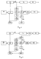
- Fig.1 to Fig.5 purely optical embodiments are shown in which the following Reference numerals are used to identify elements of the purely schematic representations of the device components. Only the homodyne variant is shown. But there are also heterodyne variants and devices in the non-optical spectral range, such as in the radar or microwave range, according to the invention realized. For the heterodyne variant, a further signal generator or a further signal output is required, which generates the second signal required for mixing.
- Fig. 1 shows the schematic representation of a first embodiment according to the invention with a mixer MI, in which the electrical signal s (t) of the signal generator SG and the echo signal e (t) of the detector DE are coupled.
- the signal s (t) of the signal generator SG is also used to impose frequency modulation on the radiation generated by the driver and laser TL.
- This optical radiation in the visible or non-visible spectral range is emitted via a transmission optical system SO and, after reflection at one or more targets or objects, is received again via a receiving optical system EO and a detector DE.
- the mixer MI uses both the signal s (t) of the signal generator SG and the signal of the beam generation of the driver and laser TL included in the received radiation.
- the result of the mixer MI is digitized via a low-pass filter TF and an analog-to-digital converter ADC and supplied to the digital signal processor DSP for signal processing.
- the total phase TP is determined by a counter ZA and also fed to the digital signal processor DSP.
- a controller ST controls the signal generator SG, so that a deviation of the signal generation can be compensated by the ideal course.
- the signal s ( t ) generated by the signal generator SG can either be varied by the controller ST in such a way that the actual emission has a linear frequency characteristic or else the error is taken into account purely algorithmically during the evaluation.
- corrections may include the deviation from the ideal behavior and their mathematical consideration can also be combined.
- Via a user interface BS the distance measuring device can be controlled.
- Fig.2 the schematic representation of a second embodiment according to the invention with a mixer MI with optically detected signal and a counter ZA for the total phase TP.
- the signal s (t) of the signal generator SG is not fed directly to the mixer MI, but it is the radiation emitted by the driver and laser TL radiation via a beam splitter SD to a second detector DE2, whose output is in turn connected to both the mixer MI and a counter ZA for determining the total phase TP connected.
- This arrangement thus uses in addition to the echo signal e ( t ) a second optically detected signal s ( t - t 0 ), which is guided over an internal path, so that influences of the driver / laser combination TL equally on both signals of the mixer MI impact.
- FIG.1 similar embodiment is in Figure 3 shown as a schematic representation of a third embodiment according to the invention with two mixers, direct electrical signal coupling and a quadrature receiver.
- the signal s ( t ) of the signal generator SG is fed to a first mixer MI1 and a second mixer MI2 with downstream low-pass filters TF and analog-to-digital converters ADC, wherein the signal of the second mixer MI2 is shifted in a 90 ° phase shifter.
- the echo signal e ( t ) of the radiation registered by the detector DE is coupled into the first mixer MI1 as well as into the second mixer MI2, so that overall a quadrature receiver results.
- Figure 4 shows the schematic representation of a second embodiment of Fig.2 similar fourth inventive embodiment with two mixers, optically detected signal s ( t - t 0 ) and a quadrature receiver.
- This fourth embodiment combines the quadrature receiver of the third embodiment of FIG Figure 3 with the optical detection of the signal s ( t - t 0 ) of the second embodiment of the Fig.2 .
- the signal s ( t ) of the signal generator SG is not supplied directly to the quadrature receiver, but the radiation emitted by the driver and laser TL radiation is passed via a beam splitter SD to a second detector DE2, which in turn is connected to the quadrature receiver.
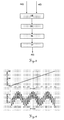
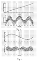
- the Fig.9-11 show numerical examples of the heterodyne case.
- the simulations were also calculated using Matlab, using the same values as in the homodyne case.
- Figure 10 shows how the interference according to equation (9) of the ideal chirp in the heterodyne case. Shown again are the frequency response (top) and mixed and sampled receive signal (bottom).
- the embodiments of the devices can be configured in a heterodyne or homodyne design, with mixers of different types, such as Gilbert cells or scanning mixers, or with replacement of one or more mixers by the sequence of superposition and non-linearity.
Landscapes
- Engineering & Computer Science (AREA)
- Physics & Mathematics (AREA)
- Computer Networks & Wireless Communication (AREA)
- General Physics & Mathematics (AREA)
- Radar, Positioning & Navigation (AREA)
- Remote Sensing (AREA)
- Electromagnetism (AREA)
- Optical Radar Systems And Details Thereof (AREA)
- Radar Systems Or Details Thereof (AREA)
Claims (13)
- Procédé de mesure de distance électro-optique avec les étapes• émission de rayonnement électromagnétique optique modulé en fréquence à n≥1 cibles à mesurer, cependant qu'un chirp est décrit en tant que fréquence appliquée au rayonnement par
 • réception du rayonnement rétrodiffusé par les n≥1 cibles,• conversion du rayonnement reçu en au moins un signal de réception par mélange homodyne ou hétérodyne,• détermination d'au moins une distance vers les n≥1 cibles à partir du signal de réception,
caractérisé en ce- qu'au moins une partie des paramètres cj est déterminée à partir du signal de réception cependant• qu'une modification de phase totale Φ tot = Φ(tb )-Φ(ta ) est mesurée dans le signal d'émission pendant un intervalle de temps connu, en particulier de l'intervalle de mesure, en particulier en comptant les passages par zéro du signal d'émission, et• qu'il est tenu compte, pour les coefficients c 1,,...,cm pour l'exploitation du signal,- d'une contrainte générale Φ(tb );c 1, ...,cm )-Φ(ta ;c 1,...,cm )=Φ tot ou- d'une contrainte linéaire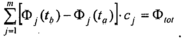
- Procédé de mesure de distance selon la revendication 1, caractérisé en ce qu'au moins la partie des paramètres cj est déterminée au moyen du procédé du maximum de vraisemblance, en particulier avec les autres paramètres du système et une durée tk assignée à au moins une distance.
- Procédé de mesure de distance selon l'une des revendications précédentes,
caractérisé en ce que l'émission de rayonnement électromagnétique optique modulé en fréquence se fait sur plusieurs cibles à mesurer et lors de la détermination les distances par rapport aux cibles à mesurer sont dérivées du signal de réception. - Procédé de mesure de distance selon l'une des revendications précédentes,
caractérisé en ce que les paramètres cj sont déterminés à chaque mesure, en particulier avec d'autres paramètres système et/ou au moins une durée tk assignée à au moins une distance. - Procédé de mesure de distance selon l'une des revendications précédentes,
caractérisé en ce que la fonction de phase est modélisée selon - des puissances,- des polynômes orthogonaux,- des ondelettes ou- des fonctions delta discrètes aux instants de balayagecomme fonctions de base.
 - Procédé de mesure de distance selon l'une des revendications 1 à 5,
caractérisé en ce que la fonction de phase Φ(t)=Φ(t;c1,..,cm ) est modélisée avec des paramètres non linéaires c1 ,...cm si bien que le problème d'optimisation à résoudre n'est pas non plus linéaire par rapport aux paramètres - Procédé de mesure de distance selon l'une des revendications précédentes,
caractérisé en ce qu'en particulier pour un petit écart du chirp de la linéarité des valeurs de départ approximatives sont calculées pour les durées tk au moyen d'analyse de fréquence et
- Produit de programme d'ordinateur avec code de programme qui est mémorisé sur un support lisible par machine ou incorporé par une onde électromagnétique, pour l'exécution du procédé selon l'une des revendications 1 à 7, lorsque le programme est exécuté dans un ordinateur.
- Dispositif de mesure de distance électro-optique pour exécuter le procédé de mesure de distance selon l'une des revendications 1 à 7 avec au moins• une source de rayonnement optique modulable (TL) pour générer et émettre un rayonnement optique sur n≥1 cibles à mesurer,• un générateur de signal (SG) pour la modulation de la source de rayonnement (TL), cependant qu'un chirp est décrit en tant que fréquence appliquée au rayonnement par
 • un détecteur (DE, DE1, DE2) pour la réception et pour la conversion de rayonnement rétrodiffusé en signaux de réception,• un processeur de signal, en particulier un processeur de signal numérique (DSP), pour le traitement des signaux de réception,• un mélangeur (MI, MI1, MI2) pour exécuter un procédé de mélange homodyne ou hétérodyne,
caractérisé en ce que le générateur de signal (SG), le détecteur (DE, DE1, DE2) et le processeur de signal sont placés et conçus tels- qu'au moins une partie des paramètres cj est déterminée à partir du signal de réception, cependant• qu'une modification de phase totale Φ tot = Φ(tb )-Φ(ta ) est mesurée dans le signal d'émission pendant un intervalle de temps connu, en particulier de l'intervalle de mesure, en particulier en comptant les passages par zéro du signal d'émission et• qu'il est tenu compte, pour les coefficients c 1,...,cm pour l'exploitation du signal,- d'une contrainte générale Φ(tb ;c 1,...,cm )-Φ(ta ;c 1,...,cm )=Φ tot ou- d'une contrainte linéaire
- Dispositif de mesure de distance selon la revendication 9, caractérisé en ce que le générateur de signal (SG), le détecteur (DE, DE1, DE2) et le processeur de signal sont placés et conçus tels que les paramètres cj sont déterminés à chaque mesure, en particulier avec d'autres paramètres système et/ou une durée tk associée au moins à une distance.
- Dispositif de mesure de distance selon l'une des revendications 9 ou 10, caractérisé par un dispositif pour déterminer la phase totale (TP) du signal d'émission, en particulier par un compteur (ZA).
- Dispositif de mesure de distance selon l'une des revendications 9 à 11, caractérisé par une suite de• superposition optique ou électrique (UE) du rayonnement rétrodiffusé avec un signal mélangé et• d'une non linéarité (NL), en particulier une non linéarité carréepour produire un terme mélangé, en particulier avec un filtre passe-bas en aval (TF).
- Dispositif de mesure de distance selon l'une des revendications 9 à 12, caractérisé par une commande (ST) qui commande le générateur de signal (SG) de telle manière que des écarts du chirp sont compensés par une allure de fréquence linéaire, en particulier en temps réel.
Priority Applications (1)
| Application Number | Priority Date | Filing Date | Title |
|---|---|---|---|
| EP05794659.2A EP1797457B1 (fr) | 2004-10-09 | 2005-09-29 | Procede de mesure de distance electro-optique faisant intervenir la determination d'une allure de fluctuation non-ideale |
Applications Claiming Priority (3)
| Application Number | Priority Date | Filing Date | Title |
|---|---|---|---|
| EP04024127A EP1645890A1 (fr) | 2004-10-09 | 2004-10-09 | Procédé de mesure de distances comprenant la détermination des caractéristiques non idéales du signal chirp |
| EP05794659.2A EP1797457B1 (fr) | 2004-10-09 | 2005-09-29 | Procede de mesure de distance electro-optique faisant intervenir la determination d'une allure de fluctuation non-ideale |
| PCT/EP2005/054900 WO2006040263A1 (fr) | 2004-10-09 | 2005-09-29 | Procede de mesure de distance electro-optique faisant intervenir la determination d'une allure de fluctuation non-ideale |
Publications (2)
| Publication Number | Publication Date |
|---|---|
| EP1797457A1 EP1797457A1 (fr) | 2007-06-20 |
| EP1797457B1 true EP1797457B1 (fr) | 2016-08-24 |
Family
ID=34926928
Family Applications (2)
| Application Number | Title | Priority Date | Filing Date |
|---|---|---|---|
| EP04024127A Withdrawn EP1645890A1 (fr) | 2004-10-09 | 2004-10-09 | Procédé de mesure de distances comprenant la détermination des caractéristiques non idéales du signal chirp |
| EP05794659.2A Expired - Lifetime EP1797457B1 (fr) | 2004-10-09 | 2005-09-29 | Procede de mesure de distance electro-optique faisant intervenir la determination d'une allure de fluctuation non-ideale |
Family Applications Before (1)
| Application Number | Title | Priority Date | Filing Date |
|---|---|---|---|
| EP04024127A Withdrawn EP1645890A1 (fr) | 2004-10-09 | 2004-10-09 | Procédé de mesure de distances comprenant la détermination des caractéristiques non idéales du signal chirp |
Country Status (7)
| Country | Link |
|---|---|
| US (1) | US7671971B2 (fr) |
| EP (2) | EP1645890A1 (fr) |
| JP (1) | JP4980916B2 (fr) |
| CN (1) | CN101036068B (fr) |
| AU (1) | AU2005293591B2 (fr) |
| CA (1) | CA2583337C (fr) |
| WO (1) | WO2006040263A1 (fr) |
Families Citing this family (17)
| Publication number | Priority date | Publication date | Assignee | Title |
|---|---|---|---|---|
| FR2912014B1 (fr) * | 2007-01-31 | 2011-05-13 | St Microelectronics Sa | Generateur d'impulsions ultra large bande dote d'une fonction integree d'emulation numerique de filtrage, et procede de transmission. |
| US8482457B2 (en) | 2009-11-27 | 2013-07-09 | Toyota Jidosha Kabushiki Kaisha | Radar apparatus |
| JP2012093143A (ja) * | 2010-10-25 | 2012-05-17 | Panasonic Corp | 障害物検知装置 |
| JP5581174B2 (ja) * | 2010-10-25 | 2014-08-27 | パナソニック株式会社 | 障害物検知装置 |
| KR101465370B1 (ko) * | 2013-12-09 | 2014-11-26 | 한국항공우주연구원 | 위상누적다항식을 이용하여 양방향 첩신호를 생성하는 장치 및 방법 |
| EP3032277B1 (fr) | 2014-12-12 | 2021-04-07 | Leica Geosystems AG | Appareil de suivi laser |
| CN109283498B (zh) * | 2017-07-21 | 2022-07-15 | 北京遥感设备研究所 | 一种线性调频脉冲信号相位误差曲线生成方法 |
| US10534084B2 (en) * | 2017-07-27 | 2020-01-14 | Blackmore Sensors & Analytics, Llc | Method and system for using square wave digital chirp signal for optical chirped range detection |
| DE102018201735B4 (de) * | 2018-02-05 | 2024-11-28 | Carl Zeiss Ag | Vorrichtung und Verfahren zum Ermitteln eines Abstandes eines bewegten Objekts |
| DE102019211832A1 (de) * | 2018-08-23 | 2020-02-27 | Mitutoyo Corporation | Messvorrichtung und messverfahren |
| JP7284652B2 (ja) * | 2018-08-23 | 2023-05-31 | 株式会社ミツトヨ | 測定装置および測定方法 |
| JP7169642B2 (ja) | 2018-11-28 | 2022-11-11 | 国立研究開発法人産業技術総合研究所 | 光学的測定装置及び測定方法 |
| KR102196035B1 (ko) * | 2018-12-26 | 2020-12-29 | (주)미래컴퍼니 | 펄스 위상 이동을 이용한 3차원 거리측정 카메라의 비선형 거리 오차 보정 방법 |
| DE102019210074A1 (de) | 2019-07-09 | 2019-10-02 | Carl Zeiss Smt Gmbh | Bildsensor sowie Vorrichtung zur Bestimmung der Position eines optischen Elements, insbesondere in einer mikrolithographischen Projektionsbelichtungsanlage |
| CN111562564B (zh) * | 2020-05-25 | 2022-04-15 | 浙江光珀智能科技有限公司 | 一种调频连续波激光测距非线性校正装置及方法 |
| CN115267808A (zh) * | 2021-04-30 | 2022-11-01 | 宁波飞芯电子科技有限公司 | 一种获取距离信息的探测方法及探测系统 |
| CN118377002A (zh) * | 2023-01-20 | 2024-07-23 | 华为技术有限公司 | 一种信号处理的方法以及相关装置 |
Family Cites Families (6)
| Publication number | Priority date | Publication date | Assignee | Title |
|---|---|---|---|---|
| GB9103945D0 (en) * | 1991-02-26 | 1991-06-12 | Philips Electronic Associated | Linearizing a swept-frequency radar |
| DE19521771A1 (de) * | 1995-06-20 | 1997-01-02 | Jan Michael Mrosik | FMCW-Abstandsmeßverfahren |
| US5719580A (en) * | 1996-06-06 | 1998-02-17 | Trw Inc. | Method and apparatus for digital compensation of VCO nonlinearity in a radar system |
| JP3719202B2 (ja) * | 2001-11-30 | 2005-11-24 | 株式会社村田製作所 | レーダの特性調整方法 |
| DE10315012B4 (de) * | 2003-04-02 | 2005-05-12 | Eads Deutschland Gmbh | Verfahren zur Linearisierung von FMCW-Radargeräten |
| US7126695B2 (en) * | 2003-10-10 | 2006-10-24 | The Boeing Company | Heterodyne frequency modulated signal demodulator and method of operating the same |
-
2004
- 2004-10-09 EP EP04024127A patent/EP1645890A1/fr not_active Withdrawn
-
2005
- 2005-09-29 US US11/576,794 patent/US7671971B2/en active Active
- 2005-09-29 JP JP2007535141A patent/JP4980916B2/ja not_active Expired - Fee Related
- 2005-09-29 CA CA2583337A patent/CA2583337C/fr not_active Expired - Fee Related
- 2005-09-29 WO PCT/EP2005/054900 patent/WO2006040263A1/fr not_active Ceased
- 2005-09-29 CN CN200580034408XA patent/CN101036068B/zh not_active Expired - Lifetime
- 2005-09-29 AU AU2005293591A patent/AU2005293591B2/en not_active Ceased
- 2005-09-29 EP EP05794659.2A patent/EP1797457B1/fr not_active Expired - Lifetime
Also Published As
| Publication number | Publication date |
|---|---|
| EP1797457A1 (fr) | 2007-06-20 |
| US7671971B2 (en) | 2010-03-02 |
| US20090135403A1 (en) | 2009-05-28 |
| AU2005293591A2 (en) | 2006-04-20 |
| WO2006040263A1 (fr) | 2006-04-20 |
| AU2005293591A1 (en) | 2006-04-20 |
| CA2583337A1 (fr) | 2006-04-20 |
| EP1645890A1 (fr) | 2006-04-12 |
| CN101036068B (zh) | 2010-05-05 |
| AU2005293591B2 (en) | 2009-10-29 |
| JP2008516213A (ja) | 2008-05-15 |
| CA2583337C (fr) | 2014-07-08 |
| CN101036068A (zh) | 2007-09-12 |
| JP4980916B2 (ja) | 2012-07-18 |
Similar Documents
| Publication | Publication Date | Title |
|---|---|---|
| EP1797457B1 (fr) | Procede de mesure de distance electro-optique faisant intervenir la determination d'une allure de fluctuation non-ideale | |
| EP2406659B1 (fr) | Mesure de distance | |
| EP1825294B1 (fr) | Procede de mesure de distance heterodyne a un seul canal | |
| EP1595110B1 (fr) | Procede et dispositif d'extraction d'informations geodesiques de distance | |
| DE69834710T2 (de) | Radarsystem | |
| EP0848829B1 (fr) | Dispositif de telemetrie | |
| EP2044459A1 (fr) | Détecteur radar à résolution angulaire | |
| DE102017211558A1 (de) | Radarsysteme und zugehörige verfahren | |
| DE102008050117A1 (de) | Kalibration einer Radareinheit mit gerätespezifischen Korrekturkurven | |
| EP1825293B1 (fr) | Procede electronique de mesure | |
| EP2440949B1 (fr) | Procédé et dispositif pour mesurer une variation de distance | |
| EP0965052B1 (fr) | Procede pour le fonctionnement d'un systeme detecteur, et systeme detecteur | |
| DE102017113730A1 (de) | Radar-frontend mit hf-oszillator-überwachung | |
| EP3581962A1 (fr) | Procédé de mesure de distance fmcw à deux faisceaux à compensation d'une erreur de mesure de distance dépendante de la vitesse | |
| DE102010040890A1 (de) | Radarsensor mit phasengeregeltem Oszillator | |
| DE102009027368B4 (de) | Mischerüberwachung | |
| DE102019128892A1 (de) | Radarsyste m mit interner rampenlinearitätsmessungsfähigkeit | |
| DE102008050327A1 (de) | Empfangsmischer zur Verringerung von Überkopplungseffekten | |
| EP3418698A1 (fr) | Réflectomètre de niveau de remplissage ayant une réflexion de référence | |
| DE112007001665B4 (de) | Radarsystem zur Umfelderfassung mit Mitteln zur Vermessung der Oszillatorkennlinie | |
| DE102023109832B3 (de) | Verfahren zur Messung einer Radialgeschwindigkeit eines Objekts bezogen auf einen Messort | |
| DE19851307B4 (de) | System und Verfahren zum Ermitteln mindestens einer physikalischen Größe | |
| WO1998038523A1 (fr) | Procede et dispositif pour la mesure de la distance et de la vitesse | |
| EP1496373B1 (fr) | Détecteur optique | |
| DE112021006774T5 (de) | Radarvorrichtung und fahrzeuginterne vorrichtung mit radarvorrichtung |
Legal Events
| Date | Code | Title | Description |
|---|---|---|---|
| PUAI | Public reference made under article 153(3) epc to a published international application that has entered the european phase |
Free format text: ORIGINAL CODE: 0009012 |
|
| 17P | Request for examination filed |
Effective date: 20070330 |
|
| AK | Designated contracting states |
Kind code of ref document: A1 Designated state(s): AT BE BG CH CY CZ DE DK EE ES FI FR GB GR HU IE IS IT LI LT LU LV MC NL PL PT RO SE SI SK TR |
|
| DAX | Request for extension of the european patent (deleted) | ||
| 17Q | First examination report despatched |
Effective date: 20120711 |
|
| GRAP | Despatch of communication of intention to grant a patent |
Free format text: ORIGINAL CODE: EPIDOSNIGR1 |
|
| INTG | Intention to grant announced |
Effective date: 20160511 |
|
| GRAS | Grant fee paid |
Free format text: ORIGINAL CODE: EPIDOSNIGR3 |
|
| GRAA | (expected) grant |
Free format text: ORIGINAL CODE: 0009210 |
|
| AK | Designated contracting states |
Kind code of ref document: B1 Designated state(s): AT BE BG CH CY CZ DE DK EE ES FI FR GB GR HU IE IS IT LI LT LU LV MC NL PL PT RO SE SI SK TR |
|
| REG | Reference to a national code |
Ref country code: GB Ref legal event code: FG4D Free format text: NOT ENGLISH |
|
| REG | Reference to a national code |
Ref country code: CH Ref legal event code: EP |
|
| REG | Reference to a national code |
Ref country code: AT Ref legal event code: REF Ref document number: 823571 Country of ref document: AT Kind code of ref document: T Effective date: 20160915 Ref country code: CH Ref legal event code: NV Representative=s name: KAMINSKI HARMANN PATENTANWAELTE AG, LI |
|
| REG | Reference to a national code |
Ref country code: IE Ref legal event code: FG4D Free format text: LANGUAGE OF EP DOCUMENT: GERMAN Ref country code: FR Ref legal event code: PLFP Year of fee payment: 12 |
|
| REG | Reference to a national code |
Ref country code: DE Ref legal event code: R096 Ref document number: 502005015339 Country of ref document: DE |
|
| REG | Reference to a national code |
Ref country code: NL Ref legal event code: FP |
|
| REG | Reference to a national code |
Ref country code: LT Ref legal event code: MG4D |
|
| PG25 | Lapsed in a contracting state [announced via postgrant information from national office to epo] |
Ref country code: FI Free format text: LAPSE BECAUSE OF FAILURE TO SUBMIT A TRANSLATION OF THE DESCRIPTION OR TO PAY THE FEE WITHIN THE PRESCRIBED TIME-LIMIT Effective date: 20160824 Ref country code: LT Free format text: LAPSE BECAUSE OF FAILURE TO SUBMIT A TRANSLATION OF THE DESCRIPTION OR TO PAY THE FEE WITHIN THE PRESCRIBED TIME-LIMIT Effective date: 20160824 Ref country code: IT Free format text: LAPSE BECAUSE OF FAILURE TO SUBMIT A TRANSLATION OF THE DESCRIPTION OR TO PAY THE FEE WITHIN THE PRESCRIBED TIME-LIMIT Effective date: 20160824 |
|
| PG25 | Lapsed in a contracting state [announced via postgrant information from national office to epo] |
Ref country code: SE Free format text: LAPSE BECAUSE OF FAILURE TO SUBMIT A TRANSLATION OF THE DESCRIPTION OR TO PAY THE FEE WITHIN THE PRESCRIBED TIME-LIMIT Effective date: 20160824 Ref country code: PT Free format text: LAPSE BECAUSE OF FAILURE TO SUBMIT A TRANSLATION OF THE DESCRIPTION OR TO PAY THE FEE WITHIN THE PRESCRIBED TIME-LIMIT Effective date: 20161226 Ref country code: LV Free format text: LAPSE BECAUSE OF FAILURE TO SUBMIT A TRANSLATION OF THE DESCRIPTION OR TO PAY THE FEE WITHIN THE PRESCRIBED TIME-LIMIT Effective date: 20160824 Ref country code: ES Free format text: LAPSE BECAUSE OF FAILURE TO SUBMIT A TRANSLATION OF THE DESCRIPTION OR TO PAY THE FEE WITHIN THE PRESCRIBED TIME-LIMIT Effective date: 20160824 Ref country code: GR Free format text: LAPSE BECAUSE OF FAILURE TO SUBMIT A TRANSLATION OF THE DESCRIPTION OR TO PAY THE FEE WITHIN THE PRESCRIBED TIME-LIMIT Effective date: 20161125 Ref country code: BE Free format text: LAPSE BECAUSE OF NON-PAYMENT OF DUE FEES Effective date: 20160930 |
|
| PG25 | Lapsed in a contracting state [announced via postgrant information from national office to epo] |
Ref country code: EE Free format text: LAPSE BECAUSE OF FAILURE TO SUBMIT A TRANSLATION OF THE DESCRIPTION OR TO PAY THE FEE WITHIN THE PRESCRIBED TIME-LIMIT Effective date: 20160824 Ref country code: RO Free format text: LAPSE BECAUSE OF FAILURE TO SUBMIT A TRANSLATION OF THE DESCRIPTION OR TO PAY THE FEE WITHIN THE PRESCRIBED TIME-LIMIT Effective date: 20160824 |
|
| REG | Reference to a national code |
Ref country code: DE Ref legal event code: R097 Ref document number: 502005015339 Country of ref document: DE |
|
| PG25 | Lapsed in a contracting state [announced via postgrant information from national office to epo] |
Ref country code: DK Free format text: LAPSE BECAUSE OF FAILURE TO SUBMIT A TRANSLATION OF THE DESCRIPTION OR TO PAY THE FEE WITHIN THE PRESCRIBED TIME-LIMIT Effective date: 20160824 Ref country code: BG Free format text: LAPSE BECAUSE OF FAILURE TO SUBMIT A TRANSLATION OF THE DESCRIPTION OR TO PAY THE FEE WITHIN THE PRESCRIBED TIME-LIMIT Effective date: 20161124 Ref country code: CZ Free format text: LAPSE BECAUSE OF FAILURE TO SUBMIT A TRANSLATION OF THE DESCRIPTION OR TO PAY THE FEE WITHIN THE PRESCRIBED TIME-LIMIT Effective date: 20160824 Ref country code: PL Free format text: LAPSE BECAUSE OF FAILURE TO SUBMIT A TRANSLATION OF THE DESCRIPTION OR TO PAY THE FEE WITHIN THE PRESCRIBED TIME-LIMIT Effective date: 20160824 Ref country code: SK Free format text: LAPSE BECAUSE OF FAILURE TO SUBMIT A TRANSLATION OF THE DESCRIPTION OR TO PAY THE FEE WITHIN THE PRESCRIBED TIME-LIMIT Effective date: 20160824 |
|
| REG | Reference to a national code |
Ref country code: IE Ref legal event code: MM4A |
|
| PG25 | Lapsed in a contracting state [announced via postgrant information from national office to epo] |
Ref country code: MC Free format text: LAPSE BECAUSE OF FAILURE TO SUBMIT A TRANSLATION OF THE DESCRIPTION OR TO PAY THE FEE WITHIN THE PRESCRIBED TIME-LIMIT Effective date: 20160824 |
|
| PLBE | No opposition filed within time limit |
Free format text: ORIGINAL CODE: 0009261 |
|
| STAA | Information on the status of an ep patent application or granted ep patent |
Free format text: STATUS: NO OPPOSITION FILED WITHIN TIME LIMIT |
|
| PG25 | Lapsed in a contracting state [announced via postgrant information from national office to epo] |
Ref country code: IE Free format text: LAPSE BECAUSE OF NON-PAYMENT OF DUE FEES Effective date: 20160929 |
|
| 26N | No opposition filed |
Effective date: 20170526 |
|
| PG25 | Lapsed in a contracting state [announced via postgrant information from national office to epo] |
Ref country code: SI Free format text: LAPSE BECAUSE OF FAILURE TO SUBMIT A TRANSLATION OF THE DESCRIPTION OR TO PAY THE FEE WITHIN THE PRESCRIBED TIME-LIMIT Effective date: 20160824 Ref country code: LU Free format text: LAPSE BECAUSE OF NON-PAYMENT OF DUE FEES Effective date: 20160929 |
|
| REG | Reference to a national code |
Ref country code: FR Ref legal event code: PLFP Year of fee payment: 13 |
|
| REG | Reference to a national code |
Ref country code: AT Ref legal event code: MM01 Ref document number: 823571 Country of ref document: AT Kind code of ref document: T Effective date: 20160929 |
|
| REG | Reference to a national code |
Ref country code: BE Ref legal event code: MM Effective date: 20160930 |
|
| PG25 | Lapsed in a contracting state [announced via postgrant information from national office to epo] |
Ref country code: AT Free format text: LAPSE BECAUSE OF NON-PAYMENT OF DUE FEES Effective date: 20160929 |
|
| PG25 | Lapsed in a contracting state [announced via postgrant information from national office to epo] |
Ref country code: HU Free format text: LAPSE BECAUSE OF FAILURE TO SUBMIT A TRANSLATION OF THE DESCRIPTION OR TO PAY THE FEE WITHIN THE PRESCRIBED TIME-LIMIT; INVALID AB INITIO Effective date: 20050929 Ref country code: CY Free format text: LAPSE BECAUSE OF FAILURE TO SUBMIT A TRANSLATION OF THE DESCRIPTION OR TO PAY THE FEE WITHIN THE PRESCRIBED TIME-LIMIT Effective date: 20160824 |
|
| PG25 | Lapsed in a contracting state [announced via postgrant information from national office to epo] |
Ref country code: TR Free format text: LAPSE BECAUSE OF FAILURE TO SUBMIT A TRANSLATION OF THE DESCRIPTION OR TO PAY THE FEE WITHIN THE PRESCRIBED TIME-LIMIT Effective date: 20160824 Ref country code: IS Free format text: LAPSE BECAUSE OF FAILURE TO SUBMIT A TRANSLATION OF THE DESCRIPTION OR TO PAY THE FEE WITHIN THE PRESCRIBED TIME-LIMIT Effective date: 20160824 |
|
| REG | Reference to a national code |
Ref country code: FR Ref legal event code: PLFP Year of fee payment: 14 |
|
| PGFP | Annual fee paid to national office [announced via postgrant information from national office to epo] |
Ref country code: NL Payment date: 20190918 Year of fee payment: 15 |
|
| PGFP | Annual fee paid to national office [announced via postgrant information from national office to epo] |
Ref country code: GB Payment date: 20190920 Year of fee payment: 15 |
|
| PGFP | Annual fee paid to national office [announced via postgrant information from national office to epo] |
Ref country code: CH Payment date: 20190919 Year of fee payment: 15 |
|
| REG | Reference to a national code |
Ref country code: CH Ref legal event code: PL |
|
| REG | Reference to a national code |
Ref country code: NL Ref legal event code: MM Effective date: 20201001 |
|
| GBPC | Gb: european patent ceased through non-payment of renewal fee |
Effective date: 20200929 |
|
| PG25 | Lapsed in a contracting state [announced via postgrant information from national office to epo] |
Ref country code: NL Free format text: LAPSE BECAUSE OF NON-PAYMENT OF DUE FEES Effective date: 20201001 |
|
| PG25 | Lapsed in a contracting state [announced via postgrant information from national office to epo] |
Ref country code: CH Free format text: LAPSE BECAUSE OF NON-PAYMENT OF DUE FEES Effective date: 20200930 Ref country code: GB Free format text: LAPSE BECAUSE OF NON-PAYMENT OF DUE FEES Effective date: 20200929 Ref country code: LI Free format text: LAPSE BECAUSE OF NON-PAYMENT OF DUE FEES Effective date: 20200930 |
|
| PGFP | Annual fee paid to national office [announced via postgrant information from national office to epo] |
Ref country code: DE Payment date: 20240918 Year of fee payment: 20 |
|
| PGFP | Annual fee paid to national office [announced via postgrant information from national office to epo] |
Ref country code: FR Payment date: 20240924 Year of fee payment: 20 |
|
| REG | Reference to a national code |
Ref country code: DE Ref legal event code: R071 Ref document number: 502005015339 Country of ref document: DE |