EP1797980A2 - Niederdruck-Kokillengiessanlage - Google Patents
Niederdruck-Kokillengiessanlage Download PDFInfo
- Publication number
- EP1797980A2 EP1797980A2 EP06125985A EP06125985A EP1797980A2 EP 1797980 A2 EP1797980 A2 EP 1797980A2 EP 06125985 A EP06125985 A EP 06125985A EP 06125985 A EP06125985 A EP 06125985A EP 1797980 A2 EP1797980 A2 EP 1797980A2
- Authority
- EP
- European Patent Office
- Prior art keywords
- die
- pressure
- fixture
- low
- station
- Prior art date
- Legal status (The legal status is an assumption and is not a legal conclusion. Google has not performed a legal analysis and makes no representation as to the accuracy of the status listed.)
- Withdrawn
Links
Images


Classifications
-
- B—PERFORMING OPERATIONS; TRANSPORTING
- B22—CASTING; POWDER METALLURGY
- B22D—CASTING OF METALS; CASTING OF OTHER SUBSTANCES BY THE SAME PROCESSES OR DEVICES
- B22D18/00—Pressure casting; Vacuum casting
- B22D18/04—Low pressure casting, i.e. making use of pressures up to a few bars to fill the mould
-
- B—PERFORMING OPERATIONS; TRANSPORTING
- B22—CASTING; POWDER METALLURGY
- B22D—CASTING OF METALS; CASTING OF OTHER SUBSTANCES BY THE SAME PROCESSES OR DEVICES
- B22D33/00—Equipment for handling moulds
- B22D33/02—Turning or transposing moulds
Definitions
- the present invention relates to a low-pressure die-casting apparatus.
- the invention is useful particularly but not exclusively in the production by low-pressure die-casting of faucets and unions for water and the like and in any case in all foundry processes which use metallic permanent dies.
- low-pressure die-casting apparatuses are usually constituted by a furnace which is adapted to produce the molten metallic mass into which a pipe is dipped in order to dispense, by feeding pressure into the furnace, said molten mass into the die.
- the molten mass is fed into the die by rising from below, so as to prevent the formation of air bubbles inside.
- a die supporting fixture is provided at the furnace and allows to perform the appropriate movements of said die in order to arrange it at the furnace, at the position for unloading the cast part or for loading the core, if provided, into the die or to arrange it proximate to all the components of the apparatus which are adapted to work on the die, such as for example the fixtures for preparing for the die filling step, which typically provide an apparatus for distributing release agent within the die (suitable to allow the separation of the cast part from said die once it has been formed) or a fixture for cleaning the inside of the die.
- the die supporting fixture is arranged so that it can slide in a motorized manner on a horizontal guide which is raised from the ground and along one side of which there are the furnace, the station for unloading the cast part (or for loading the core) and the other components of the apparatus which interact with the die.
- a typical work sequence entails positioning the die supporting fixture at the core loading station (the die is open, with its two halves arranged so as to face each other), the closure of the die and movement of the die supporting fixture toward the furnace, where low-pressure filling occurs.
- the fixture is then moved to the unloading station, which typically coincides with the core loading station, where the die is opened and the cast part is extracted by an automated extractor, which before depositing the cast part onto a conveyor belt shows it to an operator who is present and examines it in order to determine whether there are any defects.
- the die supporting fixture is then moved until the die is at the fixtures for cleaning and distributing release agent; once the operations linked to said fixtures have ended, the die is returned to the core loading station, ready for a new cycle of operations.
- the apparatus there are two furnaces arranged at the ends of the guide and there are two die supporting fixtures, each with one die, so as to allow continuous production and unloading of cast parts (when one part is being cast, the other part is being unloaded).
- the aim of the present invention is to provide a low-pressure die-casting apparatus which allows to have optimum operator control of the operations for filling the die and for unloading the cast part.
- an object of the present invention is to provide a low-pressure die-casting apparatus which allows to increase as a whole the production rate of the cast parts.
- Another object of the present invention is to provide a low-pressure die-casting apparatus which allows considerable flexibility in organizing the layout of the various components.
- Another object of the present invention is to provide a low-pressure die-casting apparatus which allows to increase the quality of the cast part.
- a low-pressure die-casting apparatus of the type which comprises:
- a low-pressure die-casting apparatus is generally designated by the reference numeral 10.
- the apparatus 10 comprises a furnace 11, which is adapted to produce the molten mass to be cast in a die (designated hereinafter by the reference numeral 12), which is arranged laterally and proximate to a guide 13 on which a die supporting fixture 14 is arranged slidingly; said fixture is associated with means for translational motion along the guide 13, which are not shown in the figures, such as for example an electric motor drive associated with a device of the rack-and-pinion type.
- the guide 13 is constituted for example by a sliding beam 16, which is raised at a certain height from the ground and is supported by pillars 17.
- the station 18 is monitored by an operator, who checks all the steps of the production of the article.
- a tray 19 which is adapted to collect the cast part once it has been extracted from the die.
- Means 20 for tilting the tray 19 from a horizontal position to a position which is inclined toward a conveyor belt 21, suitable to transfer the produced cast part toward a temporary storage unit (not shown in the figures), are associated with the station 18.
- the tilting means 20 are shown schematically, merely by way of example, by means of a hydraulic cylinder which acts below the tray 19 and is pivoted to a supporting structure.
- the conveyor belt 21 runs adjacent to the guide 13 and parallel thereto.
- the die supporting fixture 14 comprises a slider 23, which is associated with said translational motion means and is arranged on the guide 13, and a turret 24, which supports a press 25 to which the two half-dies 12a that constitute the die 12 are rigidly coupled.
- the press 25 is constituted by a frame 26 which is pivoted to a fork-like body 27, which in turn is pivoted about a horizontal axis to the turret 24, as clearly shown in Figures 1 and 4; the two mutually opposite arms 28 of the press are arranged on the frame 26 and support the two half-dies 12a; hydraulic actuators (not designated by reference numerals in the figures for the sake of simplicity), adapted to move the two mutually opposite arms 28 in order to open and close the die 12, are associated with said arms.
- a motor drive is associated with each hinge axis and is suitable to actuate rotation.
- the ends of the mutually opposite arms 28 are constituted by flanges 29 for connection to the half-dies 12a, each of which comprises a motorized coupling which is suitable to turn the half-dies 12a about three perpendicular axes.
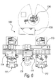
- the apparatus 10 comprises rotation means 30 for the die supporting fixture 14, which are suitable to arrange the fixture 14 so that the die 12 is located on a chosen side of the guide 13 for interaction with preset apparatus components which, in this embodiment, are constituted by means 31 for preparing for the step for filling the die 12, which is described hereinafter.
- the rotation means 30 for the die supporting fixture 14 comprise a center bearing 32 which has a vertical axis and is associated with a rotation actuator (not shown in the figures) interposed between the slider 23 and the turret 24.
- the center bearing 32 allows the fixture to rotate through at least 180°, thus moving the die 12 from one side to the other of the guide 13.
- the means 31 for preparing for the step for filling the die 12 are provided on the side of the guide 13 that lies opposite the side where the furnace 11 and the station 18 are provided; said means, in this embodiment, are constituted by a fixture 34 for cleaning by means of high-pressure liquid the interior of the die 12 and by a fixture 35 for distributing release agent inside the die 12.
- the release agent is, for example, based on liquid graphite and is sprayed onto the impressions of the die.
- the cleaning fixture 34 and the release agent distribution fixture 35 comprise a common containment housing 39 for the half-dies 12a during the operations for cleaning and distributing release agent, which allows to avoid the diffusion of cleaning liquid (water) and of release agent into the environment.
- the containment housing 39 has doors 40 which are automated for opening and closure and are adapted to allow the access of the half-dies 12a.
- High-pressure water ejectors are moved within the containment housing 39 and clean the half-dies and the release agent ejectors.
- the cleaning fixture 34 and the release agent distribution fixture 35 comprise a common robot 36, for example of the anthropomorphic type, which allows to move said ejectors.
- the robot 36 has on its wrist 37, depending on the operation to be performed, a high-pressure water ejector 38a, which is functionally connected, by means of a tube, to a high-pressure supply apparatus, or a release agent ejector 38b, which is also functionally connected, by means of a corresponding tube, to its own supply system;
- the figures show only the anthropomorphic robot 36 supporting an ejector (which can be equally a high-pressure water ejector 38a or a release agent ejector 3 8b), but not the corresponding supply systems.
- the ejectors when not in use, are arranged in a storage unit, designated schematically by the reference numeral 22, which is arranged proximate to said robot.
- the ejectors 38 of the cleaning and release agent distribution fixtures can be inserted in appropriately provided openings 41 formed in the housing 39 in order to allow the operations for cleaning and distributing release agent within the housing.
- concertina protections 42 are associated with the openings 41, one for each half-die 12a, and allow broad maneuverability of the wrist 37 of the robot 36 which moves the ejector 38 into the housing 39 without compromising the issue of containment of the fluids ejected internally.
- the ejectors for high-pressure water and for distributing release agent are always present within the protective housing and are associated with movement mechanisms which also lie inside the housing 39 and have respective actuation portions which protrude from the openings 41 (associated with the "concertina” protections 42 so as to keep said housing “sealed"), which are suitable to be moved by the robot 36.
- the operation of the apparatus is as follows.
- the die supporting fixture 14 is arranged at the station 18 where the operator is present, so that the die 12 is arranged above the tray 19; the die is open, with its impressions clean and treated with the release agent.
- the core is inserted in one of the impressions of the die and the die is then closed.
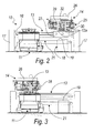
- Figures 1, 2 and 4 illustrate the moment when the die is open on the station 18, with the half-dies arranged vertically so that they face each other; the step for core insertion entails a rotation of the fork 27 so as to move the half-dies 12a to a horizontal arrangement so as to be able to rest the core; the die is then closed and the fork 27 is turned back through 90°, returning the die to the vertical position.
- the die supporting fixture 14 is moved to the furnace 11, and is arranged so that its supply port lies above the tube for feeding the molten metallic mass that arrives from the furnace 11 ( Figure 3).
- the furnace shifts upward, arranging its supply tube at the supply port of the die 12.
- the die supporting fixture 14 is moved toward the station 18, the die is opened (an arrangement which is similar to the one shown Figures 1, 2 and 4) and the half-dies are turned toward the operator; the cast part remains inside one of the two impressions and the operator can view the surface conditions of half of the article.
- the half-dies 12a are turned downward and the article is arranged on the tray 19 by gravity; the operator can thus view the other half of the article.
- the tray 19 is then tilted toward the conveyor belt 21 and the cast part slides toward said belt, which conveys the part to an accumulation unit (see Figure 4, in which the tilted tray is shown schematically in broken lines).
- the anthropomorphic robot 36 takes the high-pressure water ejector and accesses the housing 39 by means of the openings 41 with the concertina protections 42 and cleans the impressions.
- the robot 36 then replaces the high-pressure water ejector with the release agent ejector, distributing graphite on the impressions.
- the die supporting fixture 14 is turned until it is returned to the station 18, where the cycle just described begins again.
- Figure 6 shows an apparatus, designated by the reference numeral 100, in which there are two furnaces 111 arranged on a same side of the guide 113 and at its ends.
- the other die when a die is in the step for forming the article, therefore at the furnace 111, the other die, by means of the respective die supporting fixture, performs the operations for unloading, cleaning, distributing release agent and inserting the core.
- the apparatus in practice is completely automated, since each movement of a component is matched by a motor drive which is controlled by way of known types of programmable electronic means.
- the present invention provides a low-pressure die-casting apparatus which allows optimum control of all the steps on the part of the operator.
- the operator By clearing the region occupied by the operator of the fixtures for cleaning and for distributing release agent, the operator in fact easily has greater visual control of all the steps, such as for example the control of the optimum coupling between the die and the furnace, the control of any leaks of gas from the furnace and the correct rise rates of the molten metallic mass in the die.
- the provision of more space for the cleaning and release agent distribution fixtures has allowed to provide an anthropomorphic robot which allows to achieve much higher levels of quality of cleaning and release agent distribution with respect to known methods; the robot in fact allows to direct the ejectors both for water at high pressure and for the graphite according to the correct orientation of the various parts of the impressions, allowing to follow substantially its behavior.
- the operation has in fact been speeded up, since the step for picking up the part and for moving it towards the operator is no longer necessary; the operator in fact performs a first visual check on half of the part while it is still within the impression and a second visual check when it is on the tray.
- the materials employed may be any according to requirements and to the state of the art.
Landscapes
- Engineering & Computer Science (AREA)
- Mechanical Engineering (AREA)
- Molds, Cores, And Manufacturing Methods Thereof (AREA)
Applications Claiming Priority (1)
| Application Number | Priority Date | Filing Date | Title |
|---|---|---|---|
| ITPD20050362 ITPD20050362A1 (it) | 2005-12-13 | 2005-12-13 | Impianto di stampaggio a bassa pressione in conchiglia di formatura |
Publications (2)
| Publication Number | Publication Date |
|---|---|
| EP1797980A2 true EP1797980A2 (de) | 2007-06-20 |
| EP1797980A3 EP1797980A3 (de) | 2009-04-15 |
Family
ID=37888050
Family Applications (1)
| Application Number | Title | Priority Date | Filing Date |
|---|---|---|---|
| EP06125985A Withdrawn EP1797980A3 (de) | 2005-12-13 | 2006-12-13 | Niederdruck-Kokillengiessanlage |
Country Status (2)
| Country | Link |
|---|---|
| EP (1) | EP1797980A3 (de) |
| IT (1) | ITPD20050362A1 (de) |
Families Citing this family (1)
| Publication number | Priority date | Publication date | Assignee | Title |
|---|---|---|---|---|
| CN114505462A (zh) * | 2022-02-17 | 2022-05-17 | 盘星新型合金材料(常州)有限公司 | 深孔无拔模压铸件成型方法及成型装置 |
Family Cites Families (4)
| Publication number | Priority date | Publication date | Assignee | Title |
|---|---|---|---|---|
| AT325224B (de) * | 1972-04-07 | 1975-10-10 | Gravicast Patent Gmbh | Vorrichtung zum automatischen vergiessen von schmelzen, insbesondere metallschmelzen |
| IT1283090B1 (it) * | 1996-06-04 | 1998-04-07 | Imr Srl | Impianto di colata in conchiglia a bassa pressione,a potenzialita' incrementata |
| EP1270114B1 (de) * | 2001-06-18 | 2005-12-14 | Kwc Ag | Niederdruck-Kokillengiessanlage und Kokille dafür |
| ITPD20030115A1 (it) * | 2003-05-27 | 2004-11-28 | Imr Spa | Impianto di colata in gravita' con conchiglia di formatura |
-
2005
- 2005-12-13 IT ITPD20050362 patent/ITPD20050362A1/it unknown
-
2006
- 2006-12-13 EP EP06125985A patent/EP1797980A3/de not_active Withdrawn
Also Published As
| Publication number | Publication date |
|---|---|
| ITPD20050362A1 (it) | 2007-06-14 |
| EP1797980A3 (de) | 2009-04-15 |
Similar Documents
| Publication | Publication Date | Title |
|---|---|---|
| US9415441B2 (en) | Method for casting | |
| KR101070972B1 (ko) | 다이 캐스팅에 의해 금속 부품들을 제조하기 위한 방법 및장치 | |
| JP6456979B2 (ja) | 真空環境で金属を溶解して成形する装置及び方法 | |
| CA3053411C (en) | Method and apparatus for counter-gravity mold filling | |
| EP0507963B1 (de) | Betriebsvorrichtung für metallform in einer formungsmaschine | |
| CN216656332U (zh) | 金属浇铸设备 | |
| EA034025B1 (ru) | Разливочное устройство | |
| US11280548B2 (en) | Apparatus for the production of metal | |
| KR20220140771A (ko) | 로봇식 래들 터렛 시스템 | |
| US6637496B1 (en) | Rotary casting system for pressurized casting machines | |
| JP2018043268A (ja) | 鋳造装置用湯口閉塞部材、鋳造装置、離型剤塗布方法及び鋳造方法 | |
| EP1797980A2 (de) | Niederdruck-Kokillengiessanlage | |
| JPH10113760A (ja) | 低圧ダイカストプラント | |
| CN112091201A (zh) | 一种铸造浇注装置 | |
| CN211218670U (zh) | 一种全自动转盘式模具铸造生产设备 | |
| JP2003039150A (ja) | 低圧ダイキャスト装置及びその作動方法と金型 | |
| US3547181A (en) | Casting apparatus | |
| EP1481749A1 (de) | Vorrichtung und Verfahren zum Schwerkraftgiessen mit kippbarer Kokille | |
| CN118751882A (zh) | 一种圆柱不锈钢材铸造成型设备 | |
| US4103734A (en) | Counterpressure casting arrangement | |
| CN113458382B (zh) | 一种用于炮钢铸造的增压铸造设备及工艺 | |
| CN117583552A (zh) | 一种铝合金的铸造成型设备 | |
| CN217617624U (zh) | 一种砂芯制造装置 | |
| KR101387116B1 (ko) | 다이캐스팅용 원료 공급장치 및 원료 공급방법 | |
| KR100572589B1 (ko) | 수직진공 용탕단조기 |
Legal Events
| Date | Code | Title | Description |
|---|---|---|---|
| PUAI | Public reference made under article 153(3) epc to a published international application that has entered the european phase |
Free format text: ORIGINAL CODE: 0009012 |
|
| AK | Designated contracting states |
Kind code of ref document: A2 Designated state(s): AT BE BG CH CY CZ DE DK EE ES FI FR GB GR HU IE IS IT LI LT LU LV MC NL PL PT RO SE SI SK TR |
|
| AX | Request for extension of the european patent |
Extension state: AL BA HR MK YU |
|
| PUAL | Search report despatched |
Free format text: ORIGINAL CODE: 0009013 |
|
| AK | Designated contracting states |
Kind code of ref document: A3 Designated state(s): AT BE BG CH CY CZ DE DK EE ES FI FR GB GR HU IE IS IT LI LT LU LV MC NL PL PT RO SE SI SK TR |
|
| AX | Request for extension of the european patent |
Extension state: AL BA HR MK RS |
|
| AKX | Designation fees paid | ||
| REG | Reference to a national code |
Ref country code: DE Ref legal event code: 8566 |
|
| STAA | Information on the status of an ep patent application or granted ep patent |
Free format text: STATUS: THE APPLICATION IS DEEMED TO BE WITHDRAWN |
|
| 18D | Application deemed to be withdrawn |
Effective date: 20091016 |