EP1798059B1 - Schwenkvorrichtung für eine Schleuderkettenanordnung eines Kraftfahrzeuges - Google Patents
Schwenkvorrichtung für eine Schleuderkettenanordnung eines Kraftfahrzeuges Download PDFInfo
- Publication number
- EP1798059B1 EP1798059B1 EP05112233A EP05112233A EP1798059B1 EP 1798059 B1 EP1798059 B1 EP 1798059B1 EP 05112233 A EP05112233 A EP 05112233A EP 05112233 A EP05112233 A EP 05112233A EP 1798059 B1 EP1798059 B1 EP 1798059B1
- Authority
- EP
- European Patent Office
- Prior art keywords
- worm
- skid
- operating device
- skid mechanism
- axis
- Prior art date
- Legal status (The legal status is an assumption and is not a legal conclusion. Google has not performed a legal analysis and makes no representation as to the accuracy of the status listed.)
- Expired - Lifetime
Links
Images

Classifications
-
- B—PERFORMING OPERATIONS; TRANSPORTING
- B60—VEHICLES IN GENERAL
- B60B—VEHICLE WHEELS; CASTORS; AXLES FOR WHEELS OR CASTORS; INCREASING WHEEL ADHESION
- B60B39/00—Increasing wheel adhesion
- B60B39/003—Vehicle mounted non-skid chains actuated by centrifugal force
- B60B39/006—Vehicle mounted non-skid chains actuated by centrifugal force characterised by a control system for the actuation of the rotating chain wheel
-
- Y—GENERAL TAGGING OF NEW TECHNOLOGICAL DEVELOPMENTS; GENERAL TAGGING OF CROSS-SECTIONAL TECHNOLOGIES SPANNING OVER SEVERAL SECTIONS OF THE IPC; TECHNICAL SUBJECTS COVERED BY FORMER USPC CROSS-REFERENCE ART COLLECTIONS [XRACs] AND DIGESTS
- Y10—TECHNICAL SUBJECTS COVERED BY FORMER USPC
- Y10T—TECHNICAL SUBJECTS COVERED BY FORMER US CLASSIFICATION
- Y10T74/00—Machine element or mechanism
- Y10T74/18—Mechanical movements
- Y10T74/18568—Reciprocating or oscillating to or from alternating rotary
- Y10T74/18792—Reciprocating or oscillating to or from alternating rotary including worm
Definitions
- the present invention relates to an anti-skid mechanism operating device for vehicles comprising an operating unit and an operating arm pivotally supported thereby and intended to carry a rotary anti-skid device and to operate the latter between an active and a passive position.
- a device according to the preamble of claim 1 is known from EP-A-0 255 468 .
- One object of the present invention is to provide an anti-skid mechanism operating device for a vehicle, that in relation to prior art anti-skid devices, provides an anti-skid device that is less space consuming.
- Another object of the present invention is to provide an anti-skid device which is reliable in operation.
- an anti-skid mechanism operating device for vehicles comprising an operating unit and an operating arm pivotally supported thereby and intended to carry a rotary anti-skid device and to operate the latter between an active and a passive position.
- the operating device comprises a worm gear and a driven worm adapted to engage said worm gear for operation of the operating arm, wherein the driven worm is resiliently displaceable along an axis of said worm.
- the anti-skid mechanism operating device is operated between the passive and active position by a driving means for example a motor.
- the operating arm will, in the active position, engage the rotary anti-skid device with a thrust force against the tire of the vehicle.
- the driven worm is resiliently displaceable in both directions from a neutral position along said axis.
- the worm is in the neutral position when it is unloaded both from the driving means and unaffected from externally movements from the operating arm.
- the fact that the worm is resiliently movable in two directions is advantageous since the mechanism will be free from play and rattle both during operation and when the system is not in use.
- the worm is resiliently displaceable, which means that the worm has to be affected by a force when it is moved.
- said worm has a limited length causing disengagement of said worm gear due to displacement of said worm by rotation of said worm gear caused by movements from the operating arm.
- the length of the worm in combination with the resiliently displaceable characteristics can be designed to achieve desired features of the system such as spring stiffness or certain force/distance for disengagement and/or preload of the arm against the tire.
- the length of said worm admit a preloading of the operating arm without causing disengagement of said worm gear from said worm.
- the length of the worm in combination with a desired spring stiffness makes it possible to preload the mechanism without causing unintentional disengagement.
- the worm is axially supported by a resilient means providing the worm to be resiliently displaceable along an axis. It is possible to use different solutions to achieve a resilient worm along an axis.
- said resilient means is arranged around the axis/shaft and formed as a tube of a homogeneous resilient material. This design makes it possible to achieve a compact design and direct driving of the shaft of the worm without interference between the driving and the resilient means.
- said worm and driving shaft are driven by an electrical motor.
- the motor can be directly connected to the splineshaft for driving of the splined worm engaged with the splineshaft.
- the arm and worm gear will resiliently displace said worm providing a temporary disengagement of the motor to avoid damage to the device.
- This temporary disengagement of the motor is performed by displacement of the worm and the teeth of the worm gear to ratch out of engagement with the worm. This is due to that the worm transmission is self-locking and hence the worm gear will cause the worm to move along the axis instead of rotate the worm and the splineshaft.
- An advantage according to the concept of the present invention is that the device will manage to react quickly to an external impact due to the resiliently displaceable worm.
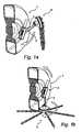
- Fig 1a is a perspective view of an anti-skid mechanism in a passive position.
- Fig 1b is a perspective view of an anti-skid mechanism in an activated position.
- Fig 2 is an exploded view of an anti-skid mechanism operating device.
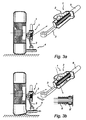
- Fig 3a is a view of an anti-skid mechanism in an activated position (chains not shown).
- Fig 3b is a view of an anti-skid mechanism in an activated position affect by an external impact.
- the anti-skid mechanism is used for engagement with a wheel of a vehicle, to be activated when the ground is slippery, providing an increased friction between the wheel and the ground, the anti-skid mechanism comprises a friction means 4 being movable by the anti-skid mechanism operating device between an active and passive position.
- the friction means 4 is constituted of a wheel with a number of chains, but any kind of friction means could be used.
- the anti-skid mechanism operating device comprises a worm transmission, driven by an electric motor 9, for operation of the arm 3 of the anti-skid mechanism between passive ( fig 1a ) and active position ( fig 1b ).
- the electric motor 9 drives the splineshaft 7, which transfer the rotation to the worm 5 via internal splines.
- fig 2 there is a tube 8, 8' of a resilient material around the shaft 7, on each side of the worm 5, acting as resilient means.
- the worm 5 is engaged with the worm wheel 6 which is connected to the operating arm 3 holding the anti-skid device 4.
- the resilient element 8, 8' can be any suitable kind of spring.
- the resilient elements 8, 8' can have the same length and stiffness, but could alternatively be designed with different length and stiffness for achieving desired properties.
- the resiliently displaceable worm 5 is movable for preloading of the operating arm 3 and rotary anti-skid device 4 against the tire, and further the worm 5 is moving in the same direction during an external impact.
- the resilient element 8 acting in the opposite direction is compressed when the arm 3 reaches its end position in the passive position. Both the resilient elements 8, 8' will prevent wear and rattling of the anti-skid mechanism since the resilient elements 8, 8' provides a flexible suspension for the movable parts.
- the anti-skid device 4 is driven by contact and friction against the side of the tire causing the device 4 to rotate and successively place one of the chains, attached to the device, in front of the wheel.
- the resilient element 8, 8' is tube-shaped and made of an elastomer material, the resilient element 8, 8' can be formed in any suitable manner to provide the worm 5 to be displaceable along the axis A.
- the embodiment described above can be modified and varied by a person skilled in the art without departing from the inventive concept defined in the claims.
- the anti-skid mechanism can be designed in a different way, as long as the worm 5 is resiliently displaceable along the axis A.
Landscapes
- Engineering & Computer Science (AREA)
- Automation & Control Theory (AREA)
- Mechanical Engineering (AREA)
- Transmission Devices (AREA)
- Axle Suspensions And Sidecars For Cycles (AREA)
- Gear Transmission (AREA)
- Automatic Cycles, And Cycles In General (AREA)
- Electric Propulsion And Braking For Vehicles (AREA)
- Automobile Manufacture Line, Endless Track Vehicle, Trailer (AREA)
- Regulating Braking Force (AREA)
Claims (8)
- Betätigungsvorrichtung für eine Gleitschutzeinrichtung (1) für Fahrzeuge, umfassend eine Betätigungseinheit (2) und einen Betätigungsarm (3), der drehbar dadurch gelagert wird und dazu dient, eine drehbare Gleitschutzvorrichtung (4) zu tragen und letztere aus einer aktiven und einer passiven Stellung zu bewegen, wobei die Betätigungsvorrichtung (2) ein Schneckengetriebe (6) und eine angetriebene Schnecke (5) umfasst, das geeignet ist, mit in das Schneckengetriebe (6) zum Betätigen des Betätigungsarms (3) einzugreifen, dadurch gekennzeichnet, dass die angetriebene Schnecke (5) elastisch entlang einer Achse (A) der Schnecke (5) verschiebbar ist.
- Betätigungsvorrichtung für eine Gleitschutzeinrichtung (1) nach Anspruch 1, wobei die angetriebene Schnecke (5) elastisch in beiden Richtungen aus einer neutralen Stellung entlang der Achse (A) verschiebbar ist.
- Betätigungsvorrichtung für eine Gleitschutzeinrichtung (1) nach einem der vorhergehenden Ansprüche, wobei die Schnecke (5) eine begrenzte Länge aufweist, die die Trennung des Schneckengetriebes (6) aufgrund der Verschiebung der Schnecke (5) durch Drehung des Schneckengetriebes (6) bewirkt, die durch die Bewegungen von dem Betätigungsarm (3) hervorgerufen werden.
- Betätigungsvorrichtung für eine Gleitschutzeinrichtung (1) nach Anspruch 3, wobei die Länge der Schnecke (5) ein Vorspannen des Betätigungsarms (3) zulässt, ohne das Lösen des Schneckengetriebes von der Schnecke (5) zu bewirken.
- Betätigungsvorrichtung für eine Gleitschutzeinrichtung (1) nach einem der vorhergehenden Ansprüche, wobei die Schnecke (5) axial von einem elastischen Mittel (8, 8') getragen wird, so dass die Schnecke (5) elastisch entlang einer Achse (A) verschiebbar ist.
- Betätigungsvorrichtung für eine Gleitschutzeinrichtung (1) nach Anspruch 5, wobei das elastische Mittel (8, 8') um die Achse (A) angeordnet ist.
- Betätigungsvorrichtung für eine Gleitschutzeinrichtung (1) nach einem der Ansprüche 5-6, wobei das elastische Mittel (8, 8') in der Form eines Rohres aus einem homogenen elastischen Material ausgebildet ist.
- Betätigungsvorrichtung für eine Gleitschutzeinrichtung (1) nach einem der vorhergehenden Ansprüche, wobei die Schnecke (5) und die Antriebswelle (7) von einem Elektromotor (9) angetrieben werden.
Priority Applications (9)
| Application Number | Priority Date | Filing Date | Title |
|---|---|---|---|
| AT05112233T ATE404388T1 (de) | 2005-12-15 | 2005-12-15 | Schwenkvorrichtung für eine schleuderkettenanordnung eines kraftfahrzeuges |
| PL05112233T PL1798059T3 (pl) | 2005-12-15 | 2005-12-15 | Urządzenie obrotowe dla odśrodkowego zespołu trakcyjnego pojazdu |
| DK05112233T DK1798059T3 (da) | 2005-12-15 | 2005-12-15 | Drejbar anordning til en centrifugal trækmontering af et köretöj |
| DE602005009002T DE602005009002D1 (de) | 2005-12-15 | 2005-12-15 | Schwenkvorrichtung für eine Schleuderkettenanordnung eines Kraftfahrzeuges |
| EP05112233A EP1798059B1 (de) | 2005-12-15 | 2005-12-15 | Schwenkvorrichtung für eine Schleuderkettenanordnung eines Kraftfahrzeuges |
| JP2008544867A JP2009519163A (ja) | 2005-12-15 | 2006-12-13 | 車両の遠心トラクション組立体の旋回装置 |
| PCT/EP2006/012001 WO2007068466A1 (en) | 2005-12-15 | 2006-12-13 | Pivoting device for a centrifugal traction assembly of a vehicle |
| US12/085,184 US7963560B2 (en) | 2005-12-15 | 2006-12-13 | Pivoting device for a centrifugal traction assembly of a vehicle |
| RU2008128880/11A RU2397072C2 (ru) | 2005-12-15 | 2006-12-13 | Поворотное устройство для центробежного тягового узла транспортного средства |
Applications Claiming Priority (1)
| Application Number | Priority Date | Filing Date | Title |
|---|---|---|---|
| EP05112233A EP1798059B1 (de) | 2005-12-15 | 2005-12-15 | Schwenkvorrichtung für eine Schleuderkettenanordnung eines Kraftfahrzeuges |
Publications (2)
| Publication Number | Publication Date |
|---|---|
| EP1798059A1 EP1798059A1 (de) | 2007-06-20 |
| EP1798059B1 true EP1798059B1 (de) | 2008-08-13 |
Family
ID=36090783
Family Applications (1)
| Application Number | Title | Priority Date | Filing Date |
|---|---|---|---|
| EP05112233A Expired - Lifetime EP1798059B1 (de) | 2005-12-15 | 2005-12-15 | Schwenkvorrichtung für eine Schleuderkettenanordnung eines Kraftfahrzeuges |
Country Status (9)
| Country | Link |
|---|---|
| US (1) | US7963560B2 (de) |
| EP (1) | EP1798059B1 (de) |
| JP (1) | JP2009519163A (de) |
| AT (1) | ATE404388T1 (de) |
| DE (1) | DE602005009002D1 (de) |
| DK (1) | DK1798059T3 (de) |
| PL (1) | PL1798059T3 (de) |
| RU (1) | RU2397072C2 (de) |
| WO (1) | WO2007068466A1 (de) |
Families Citing this family (3)
| Publication number | Priority date | Publication date | Assignee | Title |
|---|---|---|---|---|
| US20110146866A1 (en) * | 2009-12-19 | 2011-06-23 | Samad Jafari Valilou | Automatic tire chain system |
| US9731553B2 (en) * | 2012-11-06 | 2017-08-15 | Shane Evan McKenna | Pneumatically-operated rigid linear chain and sprocket actuator for deploying a vehicle snow chain traction system |
| EP3296125B1 (de) | 2016-09-15 | 2019-05-15 | VBG Group AB (Publ) | Gleitschutzanordnung mit schutzelement |
Family Cites Families (10)
| Publication number | Priority date | Publication date | Assignee | Title |
|---|---|---|---|---|
| US2283948A (en) * | 1941-04-09 | 1942-05-26 | Herbert N Ridgway | Automobile traction device |
| US2809704A (en) * | 1954-08-02 | 1957-10-15 | John J Greely | Traction device |
| US2790514A (en) * | 1956-03-12 | 1957-04-30 | Robinson Luther | Anti-skid apparatus for vehicles |
| DE3625678A1 (de) * | 1986-07-30 | 1988-02-04 | Rud Ketten Rieger & Dietz | Gleitschutzvorrichtng |
| DE3910619A1 (de) * | 1989-04-01 | 1990-10-04 | Schulz Gerd Fahrzeug Cont | Schwenkvorrichtung fuer ein schleuderkettenaggregat eines kraftfahrzeuges |
| US5076379A (en) * | 1990-11-19 | 1991-12-31 | Bahr William T | Mechanism for translation of linear motion to rotary motion |
| JPH08261294A (ja) * | 1995-03-22 | 1996-10-08 | Fuji Photo Film Co Ltd | 駆動力伝達構造 |
| US6523431B2 (en) * | 1999-10-07 | 2003-02-25 | Delphi Technologies, Inc. | Electric power steering assist mechanism |
| US7331252B2 (en) * | 2003-10-29 | 2008-02-19 | Yavor Pachov | Braking system |
| WO2005070737A1 (en) * | 2004-01-13 | 2005-08-04 | Smith Fred P | Torque-limited electric servo system for deploying a vehicle snow chain traction system |
-
2005
- 2005-12-15 DE DE602005009002T patent/DE602005009002D1/de not_active Expired - Lifetime
- 2005-12-15 EP EP05112233A patent/EP1798059B1/de not_active Expired - Lifetime
- 2005-12-15 DK DK05112233T patent/DK1798059T3/da active
- 2005-12-15 PL PL05112233T patent/PL1798059T3/pl unknown
- 2005-12-15 AT AT05112233T patent/ATE404388T1/de active
-
2006
- 2006-12-13 US US12/085,184 patent/US7963560B2/en active Active
- 2006-12-13 WO PCT/EP2006/012001 patent/WO2007068466A1/en not_active Ceased
- 2006-12-13 RU RU2008128880/11A patent/RU2397072C2/ru active
- 2006-12-13 JP JP2008544867A patent/JP2009519163A/ja active Pending
Also Published As
| Publication number | Publication date |
|---|---|
| EP1798059A1 (de) | 2007-06-20 |
| PL1798059T3 (pl) | 2009-01-30 |
| DE602005009002D1 (de) | 2008-09-25 |
| RU2008128880A (ru) | 2010-01-20 |
| JP2009519163A (ja) | 2009-05-14 |
| US20090272210A1 (en) | 2009-11-05 |
| RU2397072C2 (ru) | 2010-08-20 |
| WO2007068466A1 (en) | 2007-06-21 |
| US7963560B2 (en) | 2011-06-21 |
| DK1798059T3 (da) | 2008-12-08 |
| ATE404388T1 (de) | 2008-08-15 |
Similar Documents
| Publication | Publication Date | Title |
|---|---|---|
| KR101467422B1 (ko) | 가동 차량 패널용 선형 구동 액추에이터 | |
| US20190118872A1 (en) | Movable front spoiler device | |
| US7377529B2 (en) | Active roll control system for a vehicle suspension system | |
| EP3630548B1 (de) | Antriebsmechanismus und rückblickvorrichtung | |
| KR102606161B1 (ko) | 능동적인 공기역학적 비-역구동형 클러치 장치 | |
| EP1798059B1 (de) | Schwenkvorrichtung für eine Schleuderkettenanordnung eines Kraftfahrzeuges | |
| US6409215B1 (en) | Operating device for anti-skid devices for vehicles | |
| EP1783033A2 (de) | Elektroservolenkung mit einem Spielausgleich beim Schneckengetriebe | |
| US6848545B2 (en) | Brake actuation assembly for a vehicle | |
| WO2000041914A1 (en) | A mirror rotation mechanism | |
| CN109649478B (zh) | 电动转向的蜗轮 | |
| KR102636548B1 (ko) | 차량용 파킹장치 | |
| JP2002087295A (ja) | 電動パワーステアリング装置 | |
| EP1348880B1 (de) | Motorangetriebes Stellelement | |
| US11772613B2 (en) | Securing device for securing a standstill of a vehicle | |
| KR100695444B1 (ko) | 유격 보상장치를 구비한 랙 스트로크 가변장치를 구비한조향장치 | |
| KR100440282B1 (ko) | 자동차 조향축의 잠금장치 | |
| JP2566585Y2 (ja) | 自動車のスリップ防止装置 | |
| KR100997093B1 (ko) | 차량용 스티어링 컬럼조립체 | |
| JP4365993B2 (ja) | 車輌用ミラー電動格納装置 | |
| US7845439B2 (en) | Device for reversing the steering movement of a steering wheel shaft | |
| KR100693635B1 (ko) | 자동차의 스티어링 랙 스트로크 조절구조 | |
| KR100723723B1 (ko) | 자동차의 조향 컬럼 | |
| JPH0110261Y2 (de) | ||
| JPH04181054A (ja) | 動力伝達装置およびドアーミラー |
Legal Events
| Date | Code | Title | Description |
|---|---|---|---|
| PUAI | Public reference made under article 153(3) epc to a published international application that has entered the european phase |
Free format text: ORIGINAL CODE: 0009012 |
|
| AK | Designated contracting states |
Kind code of ref document: A1 Designated state(s): AT BE BG CH CY CZ DE DK EE ES FI FR GB GR HU IE IS IT LI LT LU LV MC NL PL PT RO SE SI SK TR |
|
| AX | Request for extension of the european patent |
Extension state: AL BA HR MK YU |
|
| 17P | Request for examination filed |
Effective date: 20071113 |
|
| AKX | Designation fees paid |
Designated state(s): AT BE BG CH CY CZ DE DK EE ES FI FR GB GR HU IE IS IT LI LT LU LV MC NL PL PT RO SE SI SK TR |
|
| GRAP | Despatch of communication of intention to grant a patent |
Free format text: ORIGINAL CODE: EPIDOSNIGR1 |
|
| RIN1 | Information on inventor provided before grant (corrected) |
Inventor name: HOLMGREN, LARS |
|
| GRAS | Grant fee paid |
Free format text: ORIGINAL CODE: EPIDOSNIGR3 |
|
| GRAA | (expected) grant |
Free format text: ORIGINAL CODE: 0009210 |
|
| AK | Designated contracting states |
Kind code of ref document: B1 Designated state(s): AT BE BG CH CY CZ DE DK EE ES FI FR GB GR HU IE IS IT LI LT LU LV MC NL PL PT RO SE SI SK TR |
|
| REG | Reference to a national code |
Ref country code: GB Ref legal event code: FG4D |
|
| REG | Reference to a national code |
Ref country code: CH Ref legal event code: EP |
|
| REG | Reference to a national code |
Ref country code: IE Ref legal event code: FG4D |
|
| REF | Corresponds to: |
Ref document number: 602005009002 Country of ref document: DE Date of ref document: 20080925 Kind code of ref document: P |
|
| RAP2 | Party data changed (patent owner data changed or rights of a patent transferred) |
Owner name: VBG GROUP AB (PUBL) |
|
| REG | Reference to a national code |
Ref country code: CH Ref legal event code: NV Representative=s name: OFFICE ERNEST T. FREYLINGER S.A. C/O SCHLUEP & DEG |
|
| REG | Reference to a national code |
Ref country code: SE Ref legal event code: TRGR |
|
| NLT2 | Nl: modifications (of names), taken from the european patent patent bulletin |
Owner name: VBG GROUP AB (PUBL) Effective date: 20081001 |
|
| REG | Reference to a national code |
Ref country code: DK Ref legal event code: T3 |
|
| PG25 | Lapsed in a contracting state [announced via postgrant information from national office to epo] |
Ref country code: IS Free format text: LAPSE BECAUSE OF FAILURE TO SUBMIT A TRANSLATION OF THE DESCRIPTION OR TO PAY THE FEE WITHIN THE PRESCRIBED TIME-LIMIT Effective date: 20081213 Ref country code: LT Free format text: LAPSE BECAUSE OF FAILURE TO SUBMIT A TRANSLATION OF THE DESCRIPTION OR TO PAY THE FEE WITHIN THE PRESCRIBED TIME-LIMIT Effective date: 20080813 |
|
| REG | Reference to a national code |
Ref country code: PL Ref legal event code: T3 |
|
| PG25 | Lapsed in a contracting state [announced via postgrant information from national office to epo] |
Ref country code: LV Free format text: LAPSE BECAUSE OF FAILURE TO SUBMIT A TRANSLATION OF THE DESCRIPTION OR TO PAY THE FEE WITHIN THE PRESCRIBED TIME-LIMIT Effective date: 20080813 Ref country code: ES Free format text: LAPSE BECAUSE OF FAILURE TO SUBMIT A TRANSLATION OF THE DESCRIPTION OR TO PAY THE FEE WITHIN THE PRESCRIBED TIME-LIMIT Effective date: 20081124 Ref country code: SI Free format text: LAPSE BECAUSE OF FAILURE TO SUBMIT A TRANSLATION OF THE DESCRIPTION OR TO PAY THE FEE WITHIN THE PRESCRIBED TIME-LIMIT Effective date: 20080813 |
|
| REG | Reference to a national code |
Ref country code: FR Ref legal event code: CD |
|
| PG25 | Lapsed in a contracting state [announced via postgrant information from national office to epo] |
Ref country code: BG Free format text: LAPSE BECAUSE OF FAILURE TO SUBMIT A TRANSLATION OF THE DESCRIPTION OR TO PAY THE FEE WITHIN THE PRESCRIBED TIME-LIMIT Effective date: 20081113 |
|
| PG25 | Lapsed in a contracting state [announced via postgrant information from national office to epo] |
Ref country code: SK Free format text: LAPSE BECAUSE OF FAILURE TO SUBMIT A TRANSLATION OF THE DESCRIPTION OR TO PAY THE FEE WITHIN THE PRESCRIBED TIME-LIMIT Effective date: 20080813 Ref country code: PT Free format text: LAPSE BECAUSE OF FAILURE TO SUBMIT A TRANSLATION OF THE DESCRIPTION OR TO PAY THE FEE WITHIN THE PRESCRIBED TIME-LIMIT Effective date: 20090113 Ref country code: CZ Free format text: LAPSE BECAUSE OF FAILURE TO SUBMIT A TRANSLATION OF THE DESCRIPTION OR TO PAY THE FEE WITHIN THE PRESCRIBED TIME-LIMIT Effective date: 20080813 Ref country code: RO Free format text: LAPSE BECAUSE OF FAILURE TO SUBMIT A TRANSLATION OF THE DESCRIPTION OR TO PAY THE FEE WITHIN THE PRESCRIBED TIME-LIMIT Effective date: 20080813 |
|
| PLBE | No opposition filed within time limit |
Free format text: ORIGINAL CODE: 0009261 |
|
| STAA | Information on the status of an ep patent application or granted ep patent |
Free format text: STATUS: NO OPPOSITION FILED WITHIN TIME LIMIT |
|
| 26N | No opposition filed |
Effective date: 20090514 |
|
| PG25 | Lapsed in a contracting state [announced via postgrant information from national office to epo] |
Ref country code: MC Free format text: LAPSE BECAUSE OF NON-PAYMENT OF DUE FEES Effective date: 20081231 Ref country code: EE Free format text: LAPSE BECAUSE OF FAILURE TO SUBMIT A TRANSLATION OF THE DESCRIPTION OR TO PAY THE FEE WITHIN THE PRESCRIBED TIME-LIMIT Effective date: 20080813 |
|
| PG25 | Lapsed in a contracting state [announced via postgrant information from national office to epo] |
Ref country code: IE Free format text: LAPSE BECAUSE OF NON-PAYMENT OF DUE FEES Effective date: 20081215 |
|
| PG25 | Lapsed in a contracting state [announced via postgrant information from national office to epo] |
Ref country code: LU Free format text: LAPSE BECAUSE OF NON-PAYMENT OF DUE FEES Effective date: 20081215 Ref country code: HU Free format text: LAPSE BECAUSE OF FAILURE TO SUBMIT A TRANSLATION OF THE DESCRIPTION OR TO PAY THE FEE WITHIN THE PRESCRIBED TIME-LIMIT Effective date: 20090214 Ref country code: CY Free format text: LAPSE BECAUSE OF FAILURE TO SUBMIT A TRANSLATION OF THE DESCRIPTION OR TO PAY THE FEE WITHIN THE PRESCRIBED TIME-LIMIT Effective date: 20080813 |
|
| PG25 | Lapsed in a contracting state [announced via postgrant information from national office to epo] |
Ref country code: GR Free format text: LAPSE BECAUSE OF FAILURE TO SUBMIT A TRANSLATION OF THE DESCRIPTION OR TO PAY THE FEE WITHIN THE PRESCRIBED TIME-LIMIT Effective date: 20081114 |
|
| REG | Reference to a national code |
Ref country code: FR Ref legal event code: PLFP Year of fee payment: 11 |
|
| REG | Reference to a national code |
Ref country code: FR Ref legal event code: PLFP Year of fee payment: 12 |
|
| REG | Reference to a national code |
Ref country code: FR Ref legal event code: PLFP Year of fee payment: 13 |
|
| PGFP | Annual fee paid to national office [announced via postgrant information from national office to epo] |
Ref country code: TR Payment date: 20201202 Year of fee payment: 16 |
|
| PGFP | Annual fee paid to national office [announced via postgrant information from national office to epo] |
Ref country code: FI Payment date: 20201217 Year of fee payment: 16 Ref country code: SE Payment date: 20201130 Year of fee payment: 16 Ref country code: AT Payment date: 20201217 Year of fee payment: 16 Ref country code: FR Payment date: 20201217 Year of fee payment: 16 Ref country code: CH Payment date: 20201218 Year of fee payment: 16 Ref country code: GB Payment date: 20201218 Year of fee payment: 16 Ref country code: DK Payment date: 20201218 Year of fee payment: 16 |
|
| PGFP | Annual fee paid to national office [announced via postgrant information from national office to epo] |
Ref country code: BE Payment date: 20201223 Year of fee payment: 16 Ref country code: PL Payment date: 20201208 Year of fee payment: 16 |
|
| PGFP | Annual fee paid to national office [announced via postgrant information from national office to epo] |
Ref country code: NL Payment date: 20201214 Year of fee payment: 16 |
|
| PGFP | Annual fee paid to national office [announced via postgrant information from national office to epo] |
Ref country code: IT Payment date: 20201221 Year of fee payment: 16 |
|
| PGFP | Annual fee paid to national office [announced via postgrant information from national office to epo] |
Ref country code: DE Payment date: 20201217 Year of fee payment: 16 |
|
| REG | Reference to a national code |
Ref country code: DE Ref legal event code: R119 Ref document number: 602005009002 Country of ref document: DE |
|
| REG | Reference to a national code |
Ref country code: FI Ref legal event code: MAE |
|
| REG | Reference to a national code |
Ref country code: DK Ref legal event code: EBP Effective date: 20211231 |
|
| REG | Reference to a national code |
Ref country code: CH Ref legal event code: PL |
|
| REG | Reference to a national code |
Ref country code: SE Ref legal event code: EUG |
|
| REG | Reference to a national code |
Ref country code: NL Ref legal event code: MM Effective date: 20220101 |
|
| REG | Reference to a national code |
Ref country code: AT Ref legal event code: MM01 Ref document number: 404388 Country of ref document: AT Kind code of ref document: T Effective date: 20211215 |
|
| GBPC | Gb: european patent ceased through non-payment of renewal fee |
Effective date: 20211215 |
|
| PG25 | Lapsed in a contracting state [announced via postgrant information from national office to epo] |
Ref country code: FI Free format text: LAPSE BECAUSE OF NON-PAYMENT OF DUE FEES Effective date: 20211215 |
|
| REG | Reference to a national code |
Ref country code: BE Ref legal event code: MM Effective date: 20211231 |
|
| PG25 | Lapsed in a contracting state [announced via postgrant information from national office to epo] |
Ref country code: NL Free format text: LAPSE BECAUSE OF NON-PAYMENT OF DUE FEES Effective date: 20220101 |
|
| PG25 | Lapsed in a contracting state [announced via postgrant information from national office to epo] |
Ref country code: SE Free format text: LAPSE BECAUSE OF NON-PAYMENT OF DUE FEES Effective date: 20211216 Ref country code: GB Free format text: LAPSE BECAUSE OF NON-PAYMENT OF DUE FEES Effective date: 20211215 Ref country code: DE Free format text: LAPSE BECAUSE OF NON-PAYMENT OF DUE FEES Effective date: 20220701 Ref country code: AT Free format text: LAPSE BECAUSE OF NON-PAYMENT OF DUE FEES Effective date: 20211215 |
|
| PG25 | Lapsed in a contracting state [announced via postgrant information from national office to epo] |
Ref country code: FR Free format text: LAPSE BECAUSE OF NON-PAYMENT OF DUE FEES Effective date: 20211231 Ref country code: BE Free format text: LAPSE BECAUSE OF NON-PAYMENT OF DUE FEES Effective date: 20211231 |
|
| PG25 | Lapsed in a contracting state [announced via postgrant information from national office to epo] |
Ref country code: LI Free format text: LAPSE BECAUSE OF NON-PAYMENT OF DUE FEES Effective date: 20211231 Ref country code: CH Free format text: LAPSE BECAUSE OF NON-PAYMENT OF DUE FEES Effective date: 20211231 |
|
| PG25 | Lapsed in a contracting state [announced via postgrant information from national office to epo] |
Ref country code: IT Free format text: LAPSE BECAUSE OF NON-PAYMENT OF DUE FEES Effective date: 20211215 Ref country code: DK Free format text: LAPSE BECAUSE OF NON-PAYMENT OF DUE FEES Effective date: 20211231 |
|
| PG25 | Lapsed in a contracting state [announced via postgrant information from national office to epo] |
Ref country code: PL Free format text: LAPSE BECAUSE OF NON-PAYMENT OF DUE FEES Effective date: 20211215 |
|
| PG25 | Lapsed in a contracting state [announced via postgrant information from national office to epo] |
Ref country code: PL Free format text: LAPSE BECAUSE OF NON-PAYMENT OF DUE FEES Effective date: 20211215 |
|
| PG25 | Lapsed in a contracting state [announced via postgrant information from national office to epo] |
Ref country code: TR Free format text: LAPSE BECAUSE OF NON-PAYMENT OF DUE FEES Effective date: 20211215 |