EP1798065B1 - Profil de bande de roulement de pneumatiques avec lamelles - Google Patents
Profil de bande de roulement de pneumatiques avec lamelles Download PDFInfo
- Publication number
- EP1798065B1 EP1798065B1 EP06123499A EP06123499A EP1798065B1 EP 1798065 B1 EP1798065 B1 EP 1798065B1 EP 06123499 A EP06123499 A EP 06123499A EP 06123499 A EP06123499 A EP 06123499A EP 1798065 B1 EP1798065 B1 EP 1798065B1
- Authority
- EP
- European Patent Office
- Prior art keywords
- profile block
- profile
- extension
- block row
- groove
- Prior art date
- Legal status (The legal status is an assumption and is not a legal conclusion. Google has not performed a legal analysis and makes no representation as to the accuracy of the status listed.)
- Not-in-force
Links
- 238000005452 bending Methods 0.000 claims 1
- 230000002093 peripheral effect Effects 0.000 description 10
- 238000005096 rolling process Methods 0.000 description 8
- XLYOFNOQVPJJNP-UHFFFAOYSA-N water Substances O XLYOFNOQVPJJNP-UHFFFAOYSA-N 0.000 description 5
- 238000001035 drying Methods 0.000 description 3
- 230000007704 transition Effects 0.000 description 3
- 230000000630 rising effect Effects 0.000 description 2
- 238000005299 abrasion Methods 0.000 description 1
- 230000001154 acute effect Effects 0.000 description 1
- 230000015572 biosynthetic process Effects 0.000 description 1
- 230000000694 effects Effects 0.000 description 1
Images


Classifications
-
- B—PERFORMING OPERATIONS; TRANSPORTING
- B60—VEHICLES IN GENERAL
- B60C—VEHICLE TYRES; TYRE INFLATION; TYRE CHANGING; CONNECTING VALVES TO INFLATABLE ELASTIC BODIES IN GENERAL; DEVICES OR ARRANGEMENTS RELATED TO TYRES
- B60C11/00—Tyre tread bands; Tread patterns; Anti-skid inserts
- B60C11/03—Tread patterns
- B60C11/0302—Tread patterns directional pattern, i.e. with main rolling direction
-
- B—PERFORMING OPERATIONS; TRANSPORTING
- B60—VEHICLES IN GENERAL
- B60C—VEHICLE TYRES; TYRE INFLATION; TYRE CHANGING; CONNECTING VALVES TO INFLATABLE ELASTIC BODIES IN GENERAL; DEVICES OR ARRANGEMENTS RELATED TO TYRES
- B60C11/00—Tyre tread bands; Tread patterns; Anti-skid inserts
- B60C11/03—Tread patterns
- B60C11/12—Tread patterns characterised by the use of narrow slits or incisions, e.g. sipes
-
- B—PERFORMING OPERATIONS; TRANSPORTING
- B60—VEHICLES IN GENERAL
- B60C—VEHICLE TYRES; TYRE INFLATION; TYRE CHANGING; CONNECTING VALVES TO INFLATABLE ELASTIC BODIES IN GENERAL; DEVICES OR ARRANGEMENTS RELATED TO TYRES
- B60C11/00—Tyre tread bands; Tread patterns; Anti-skid inserts
- B60C11/03—Tread patterns
- B60C11/12—Tread patterns characterised by the use of narrow slits or incisions, e.g. sipes
- B60C11/1204—Tread patterns characterised by the use of narrow slits or incisions, e.g. sipes with special shape of the sipe
- B60C2011/1213—Tread patterns characterised by the use of narrow slits or incisions, e.g. sipes with special shape of the sipe sinusoidal or zigzag at the tread surface
-
- B—PERFORMING OPERATIONS; TRANSPORTING
- B60—VEHICLES IN GENERAL
- B60C—VEHICLE TYRES; TYRE INFLATION; TYRE CHANGING; CONNECTING VALVES TO INFLATABLE ELASTIC BODIES IN GENERAL; DEVICES OR ARRANGEMENTS RELATED TO TYRES
- B60C11/00—Tyre tread bands; Tread patterns; Anti-skid inserts
- B60C11/03—Tread patterns
- B60C11/12—Tread patterns characterised by the use of narrow slits or incisions, e.g. sipes
- B60C11/1236—Tread patterns characterised by the use of narrow slits or incisions, e.g. sipes with special arrangements in the tread pattern
- B60C2011/1245—Tread patterns characterised by the use of narrow slits or incisions, e.g. sipes with special arrangements in the tread pattern being arranged in crossing relation, e.g. sipe mesh
-
- B—PERFORMING OPERATIONS; TRANSPORTING
- B60—VEHICLES IN GENERAL
- B60C—VEHICLE TYRES; TYRE INFLATION; TYRE CHANGING; CONNECTING VALVES TO INFLATABLE ELASTIC BODIES IN GENERAL; DEVICES OR ARRANGEMENTS RELATED TO TYRES
- B60C11/00—Tyre tread bands; Tread patterns; Anti-skid inserts
- B60C11/03—Tread patterns
- B60C11/12—Tread patterns characterised by the use of narrow slits or incisions, e.g. sipes
- B60C11/1272—Width of the sipe
- B60C2011/1277—Width of the sipe being narrow, i.e. less than 0.3 mm
Definitions
- the invention relates to a tread pattern of a pneumatic vehicle tire - especially a winter tire - arranged with at least one over the circumference of the vehicle pneumatic tire profile block row arranged in the circumferential direction U, each separated by transverse grooves profile block elements with a formed in the radially outer surface of profile block elements of the profile block row latticed fine sipe system.
- tread patterns of winter tires known with over the circumference of the vehicle pneumatic tire extended profile block row arranged in the circumferential direction U behind the other, each separated by transverse grooves profile block elements formed in the radially outer surface of the profile block elements of the profile block row parallel rectilinear or sinusoidal corrugated fine incisions.
- This training allow by a very limited number of parallel sipes grip edges for good snow grip and flexibility of the profile block mainly in one direction.
- tread strips of winter tires are known with over the circumference of the vehicle pneumatic tire extended profile block row arranged in the circumferential direction U behind each other, each separated by transverse grooves profile block elements, in which in the radially outer surface of the profile block elements of the profile block row lattice-shaped fine incision systems, each extending over the entire Protruding profile block element, known.
- the fine incision grids enable a high grip edge number and a high degree of flexibility of the profile block cut-out elements framed by the fine incision grille for a good snow grip in the longitudinal and in the transverse direction.
- the high flexibility of the entire tread block element which is accompanied by these fine incision grids, can lead to high block deformation, as a result of which all drying properties such as, for example, traction, handling and also aquaplaning properties can be negatively influenced.
- a tread pattern of a pneumatic vehicle tire according to the features of the preamble of claim 1 is known.
- the known tire has first profile block rows, which are arranged near the center of the tire, on whose profile block elements are each separated by a narrow transverse groove.
- the adjacent to the tire shoulder facing profile block row is formed with tread block elements, which are each separated by a wide transverse groove.
- Each profile block element of the first profile block row is assigned exactly one profile block element of the second profile block row and vice versa.
- Each narrow transverse groove of the first profile block row is assigned a wide profile block row of the second profile block row.
- profile block elements of the profile block rows formed only very short, although the water drainage is improved, but the circumferential stiffness is further reduced. If the profile block elements of the two profile block rows formed longer, although the circumferential stiffness is increased, but the water drainage is reduced, yet the consistently wide grooves cause a limitation of the circumferential stiffness.
- the invention is therefore based on the object, a tread pattern of a pneumatic vehicle tire - especially a winter tire - with at least one over the circumference of the vehicle pneumatic tire extended profile block row arranged in the circumferential direction U behind each other, each made possible by transverse grooves separate block block elements, in which the great advantages of a grid-shaped Fine incision system can be associated with improving the dry properties of the vehicle tire.
- the object is achieved by the formation of a tread pattern of a pneumatic vehicle tire - especially a winter tire - with at least one over the circumference of the pneumatic vehicle tire tread row arranged in the circumferential direction U behind each other, each separated by transverse grooves profile block elements according to the features of claim 1 with a in the radially outer surface of profile block elements of the profile block row formed lattice-shaped fine sipe system, with two formed in the radially outer surface of the profile block element zones extending axially along the extension of the lattice-shaped sipe system over the entire axial extent of the lattice-shaped sipe system in the profile block element and in the circumferential direction between one of the two the profile block element in the circumferential direction to a transverse groove limiting profile block element edge and the grid-shaped n fine sipe system over a circumferentially measured distance w with w> 0 mm out, which is formed in the circumferential direction (U) of the pneumatic vehicle tire two successively arranged profile block elements
- the profile block elements are stiffened in the edge area important for the drying properties, with fine-cut lattices in the interior of the profile block element, the high density and number of grip edges and flexibility the framed by the fine incision grating profile block cutting elements for safe grip on snow and snow-like ground both in the axial and in the circumferential direction of the pneumatic vehicle tire allows.
- the lattice-shaped sipe system of a profile block element in each case over the entire axial extent of the tread block element in the circumferential extension region of the lattice-shaped sipe system within the axial extension width TA of the ground contact surface of the pneumatic vehicle tire in the assembled, loaded operating condition under standard conditions (according to ETRTO standards).
- a tread pattern according to the features of claim 3, wherein one or more of the profile block elements of a profile block turn in their radially outer surface having a plurality of - in particular two - arranged in the circumferential direction one behind the other and spaced from each other lattice-shaped fine incision systems, each having a circumferentially formed between the successively arranged lattice-shaped fine incision systems zone extending axially along the extension of the lattice-shaped sipe systems over the entire axial extent of the lattice-shaped sipe systems in the profile block element over a circumferentially measured distance w with w> 0 mm out, which is formed free of fine incisions.
- the handling properties and the aquaplaning properties can be positively influenced.
- the handling properties and the aquaplaning properties can be positively influenced.
- Particularly advantageous is a design of a tread pattern according to the features of claim 6, wherein the first profile block row is a shoulder profile block row, wherein the second profile block row axially adjacent to the shoulder profile block row of the shoulder profile block row through a over the entire circumference of Pneumatic vehicle tire extends trained circumferential groove axially spaced profile block row is.
- the handling properties can be positively influenced.
- This allows an optimal stiffness distribution in the transverse direction of the pneumatic vehicle tire in the conflict of objectives from handling properties on a dry surface compared to mileage of the pneumatic vehicle tire.
- B ⁇ (0.18 TA) it can be made possible that the center rib in the aquaplaning case, such as a ship's bow, effectively cuts through the water film even during high slip.
- a first groove portion (16 ') of a groove is formed, which separates the tread rib axially from the tread block element, which includes an angle ( ⁇ ) extending to the axial of the pneumatic vehicle tire is formed, and to form a kink in the axial direction to the shoulder profile block row forming the first block profile in a second groove portion (16 ") of the groove merges, the profile block element from the circumferentially ordered by the profile block element of the profile block row wherein the second groove portion (16 ") of the groove extends to include an angle ( ⁇ ) to the axial of the vehicle pneumatic tire.
- a design of a tread strip according to the features of claim 13, wherein the first groove portion (16 ') of the groove (16) in its measured perpendicular to their extension direction width, starting from a width a along its extension up to a width b at the Kinking point - in particular linear - increases, wherein the second groove portion (16 ") of the groove (16) is formed in its measured perpendicular to their extension direction width with constant width b along its extension, wherein for the widths a, b and c applies: a ⁇ b ⁇ c, wherein in particular (1,2 a) ⁇ b ⁇ (2,3 a), the drainage from the inside of the profile can thereby be optimized.
- tread pattern is formed directionally bound.
- the handling properties, the aquaplaning properties, snow and ice grip can be positively influenced.
- the in Fig. 1 and 2 illustrated pneumatic vehicle tire 1 is designed in particular as a radial tire and preferably a car tire or a tire for light commercial vehicles.
- the pneumatic vehicle tire is provided with a tread pattern 2, which is particularly suitable for use in wintry driving conditions.
- the tread pattern 2 is considered over its width TA, which corresponds to the lathe width and thus the width of the ground contact patch of the pneumatic vehicle tire in the mounted, loaded operating condition under standard conditions (according to ETRTO standards).
- Fig.2 is entered the axial direction A of the pneumatic vehicle tire with arrow.
- the circumferential direction U of the pneumatic vehicle tire is indicated by arrow.
- tread profile 2 is a running direction bound designed profile. This means that tires with this profile have a preferred unwinding direction, which in Fig. 1 and 2 indicated by the arrow F, which is opposite to in Fig. 2 with arrow registered circumferential direction U has, and that Therefore, such tires are to be mounted according to their unwinding on the vehicle.
- the tread pattern 2 is formed in the axial direction, starting from the left tire shoulder to the right tire shoulder out of a left shoulder profile block row 3, a circumferential groove 4, a middle profile band 5, a circumferential groove 6 and a right shoulder profile block row 7, each in the circumferential direction U extend over the entire circumference of the pneumatic vehicle tire.
- the left shoulder profile block row 3 is axially separated axially from the middle profile band 5 by the circumferential groove 4 and the middle profile band 5 from the right shoulder profile block row 7 by the circumferential groove 6.
- the left shoulder profile block row 3 extends as well as the right shoulder profile block row 7 over the entire circumference of the pneumatic vehicle tire in the circumferential direction U and is formed in each case from a plurality of circumferentially U successively arranged profile block elements 11 and 14 respectively.
- the profile block elements 11 of the shoulder profile block row 3 arranged one behind the other in the circumferential direction U are separated in the circumferential direction U in an alternating sequence by transverse grooves 15 or by transverse grooves 38.
- the in the circumferential direction U successively arranged profile block elements 14 of the shoulder profile block row 7 in the circumferential direction U in an alternating sequence by transverse grooves 19 and transverse grooves 18 separated from each other.
- the center profile band 5 is formed from a central over the circumference of the vehicle pneumatic tire in the circumferential direction U aligned profiled rib 9, the axial edges are formed substantially over the circumference of the vehicle pneumatic tire distributed first circumferential portions, seen in the counter to the rolling direction F registered circumferential direction U below Inclusion of an inclination angle to the axial A of the tread rib 9 axially pointing away outwards to the respective tire shoulder inclined and between each in the circumferential direction relative to the first peripheral portions significantly shorter second peripheral portions are formed, in which the respective flank have an axially oppositely rising offset portion in the axial direction to the rib center of the tread rib 9 out with a much smaller angle of inclination to the axial A.
- the profile block elements 12 arranged one behind the other in the circumferential direction U of the pneumatic vehicle tire form a profile block row ajar in the circumferential direction U of the pneumatic vehicle tire.
- the profile block elements 13 form a profile block row ajar in the circumferential direction U of the pneumatic vehicle tire over the offset to the profile rib ,
- Each tread block element 12 is axially separated along its extension in the circumferential direction U, starting from the position of the respective short offset of the tread rib 9 along a first peripheral portion of the tread rib 9 by a first extension portion 16 'of a groove 16, which at the opposite end of the short offset of the extension region of the first peripheral section of the tread rib 9, forming a fold directed axially outwards towards the shoulder profile block row 3, into a second section 16 "of the groove 16 which separates the tread block element 12 from the next tread block element 12 closest to the circumferential direction U.
- each tread block element is 13 along its extension in the circumferential direction U, starting from the position of the respective short offset of the tread rib 9 along a first circumferential portion of the tread rib 9 by a first extension portion 17 'of a groove 17 axially separated., Which at the opposite end of the short offset extension of the first peripheral portion of the tread rib 9 to form a axially outward to the shoulder profile block row 7 toward Knicks in a second Section 17 "passes over the groove 17, which separates the tread block element 13 from the next in the circumferential direction U subsequent profile block element 13.
- a second peripheral section of the profile rib 9 begins, in which the latter respectively with its groove 16 and 16 .
- Groove flank formed with the groove 17 is formed with the offset directed axially inward.
- the offset again forms a blunt end of a new section 16 'of the groove 16 or of the section 17' of the groove 17 which, starting from the offset in the circumferential direction U, separates the next profile block element 12 or 13 from the profile rib 9.
- the gap width is an embodiment 1mm to 2mm wide, for example, 1 mm wide, selected.
- the gap is at most three times as deep (in the radial direction) as wide.
- the grooves 16 and the grooves 17 are in their entire extension region 16 'and 17' respectively rectilinear, but formed in the illustrated circumferential direction U with continuously increasing width of the groove, starting from a width a to a width b, the width of the Grooves respectively perpendicular to its direction of extent and in the radially outer contact surface of the tire for Road surface is measured.
- Fig. 2 is the example of the section 17 'of a groove 17 "the width a at the beginning of the section 17' and the width b at the end of the section 17 'registered.
- the grooves 16 or the grooves 17 likewise extend in their extension region 16 "or 17" with a straight course, but are formed in this extension region with a constant groove width c, where c ⁇ b> a.
- widths a and b are chosen such that for a and b: (1,2 a) ⁇ b ⁇ (2,3 a)
- each groove 16 In its axial extension over the circumferential groove 4, each groove 16 merges into a transverse groove 15 of the profile block row 3. Likewise, in its axial extension over the circumferential groove 6 each groove 17 in each case in a transverse groove 19 of the profile block row 7 over.
- the sections 16 'and 17' of the grooves 16 and 17 with their extension course each include a pitch angle ⁇ to the axial A of the pneumatic vehicle tire
- the grooves 16 and 17 include with their extension course in each case a pitch angle ⁇ to the axial A of the pneumatic vehicle tire and the transverse grooves 15 and 19 of the shoulder profile block row 3 and 7 with their extension course in each case a pitch angle ⁇ to the axial A of the pneumatic vehicle tire.
- the pitch angles ⁇ , ⁇ and ⁇ the following applies: ⁇ > ⁇ > ⁇ ., Where 90 ° ⁇ 70 °, 70 ° ⁇ 25 ° and 25 ° ⁇ 5 °.
- the pitch angles ⁇ , ⁇ and ⁇ are chosen as follows: 90 ⁇ ° ⁇ ⁇ ⁇ 80 ⁇ ° . 50 ⁇ ° ⁇ ß ⁇ 30 ⁇ ° and 20 ⁇ ° ⁇ ⁇ ⁇ 10 ⁇ ° ,
- the grooves 16 with the transverse grooves 15 and the grooves 17 with the transverse grooves 19 form a V-shaped profile profile of the tread pattern 2 of the pneumatic vehicle tire.
- the profile block elements 12 and 13 are formed at their profile grooves 16 and 17 limiting Profilblockelementflanken each in the bent transition region between the groove portions 16 'and 16 "or between the groove portions 17' to 17" curved under a radius of curvature R 1 edge profile.
- the profile block elements 11 of the profile block row 3 are formed on its axially to the circumferential groove 4, the profile block elements 11 delimiting edge with the same direction of inclination to the axial A as the edge profile of the profile block elements 12 at its the groove portion 16 'of the grooves 16 delimiting edge.
- the profile block elements 11 of the profile block row 3 are formed on their flank, which delimits the profile block elements 11 axially parallel to the edge profile of the profile block elements 12 at their edge defining the groove section 16 'of the grooves 16.
- the profile block elements 14 of the profile block row 7 are formed on their axially to the circumferential groove 6, the profile block elements 14 delimiting flanks with the same direction of inclination to the axial A as the edge profile of the profile block elements 13 at its the groove portion 17 'of the grooves 17 delimiting edge.
- the profile block elements 14 of the profile block row 7 are formed on its axially to the circumferential groove 6, the profile block elements 14 delimiting flanks with a parallel to the edge profile of the profile block elements 13 at its the groove portion 17 'of the grooves 17 delimiting edge.
- the one profile block element 11 to the circumferential groove 4 in each case limiting edge extends in the circumferential direction U (counter to the rolling direction F) each to the next in the circumferential direction U the respective profile block element 11 limiting transverse groove 15 and 38.
- the profile block element 14 to the circumferential groove 6 towards each limiting Flank extends in the circumferential direction U (opposite to the rolling direction F) each to the In these transition regions between the circumferential groove 4 and transverse groove 38 and 15 and between the circumferential groove 6 and transverse groove 18 and 19, the respective profile block element 11 and 14 with its edge profile with a Curvature radius R 2 formed curved.
- the radii of curvature R 2 and R 1 are chosen such that they are: R 2 ⁇ R 1
- the transverse grooves 38 terminate in their axial extension to the middle profile band 5 out blunt in the circumferential groove 4. Likewise end the transverse grooves 18 of the profile block row 7 in its axial extension to the middle profile band 5 out blunt in the circumferential groove 6.
- the transverse grooves 38 are in their extension direction rectilinear and formed parallel to the transverse grooves 15.
- the transverse grooves 18 are also rectilinear in their direction of extension and formed to extend parallel to the transverse grooves 19.
- the transverse grooves 38 and 18 are formed with a width e, the transverse grooves 18 and 15 are formed with a width d, wherein the width of the grooves is measured in each case perpendicular to its direction of extent and in the radially outer contact surface of the tire to the road surface. c ⁇ d.
- e ⁇ d where (0.3 d) ⁇ e ⁇ (0.95 d).
- the profile block elements 33 of the shoulder profile block row 3 extend in the axial direction within the contact width TA, starting from in Fig. 2 Likewise, the edge of the contact width TA registered in the profile block elements 33 of the shoulder profile block row 7 within the contact width TA extends from the right-entry edge of the contact width TA in the axial direction to the circumferential groove 6 over a maximum axial extent of the width D.
- the profile block elements 12 and the profile block elements 13 each extend in the axial direction over a maximum axial extension of the width C.
- the profile rib 5 extends in the axial direction over a maximum axial extent of the width B.
- the axial widths B, C and D are the widths in the radially outer circumferential surface of the pneumatic vehicle tire, which is the contact surface to the road surface.
- the axial widths B, C and D respectively correspond to the axial extension widths which result in the circumferential direction of the pneumatic vehicle tire when the respective profile block element 11, 14, 12, 13 or the profile rib 9 projects.
- the profile block elements 11 and 14 of the shoulder profile block rows 3 and 7, the profile block elements 12 and 13 and the profile rib 9 are designed so that for the widths of their maximum axial extent applies: D> C> B with B ⁇ (0.18 TA).
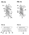
- profile block elements 11 of the shoulder profile block row 3, as well as the profile block elements 14 of the shoulder profile block row 7 each with a sipe mesh 21 consisting of in the respective profile block element 11 and 14 parallel aligned in the axial direction A of the pneumatic vehicle equidistantly spaced sipes 23 and also within the profile block element eleventh or 14 respectively parallel aligned sipes 24 formed.
- the sipes 23 are along their extension in the direction of the registered circumferential direction U (ie counter to the rolling direction F) additionally formed with an axial direction component in the direction of the crown region of the pneumatic vehicle tire and thus the circumferential rib 9 out including a pitch angle ⁇ 1 to the axial A, wherein for ⁇ 1 : 50 ° ⁇ ⁇ 1 ⁇ 85 °.
- ⁇ 1 55 ° ⁇ ⁇ 1 ⁇ 80 °.
- ⁇ 1 60 °.
- the sipes 24 include a pitch angle ⁇ 1 to the extension direction of the sipes 23 within a tread block element 11 or 14, for which the following applies: 30 ° ⁇ ⁇ 1 ⁇ 150 °. In a particular embodiment: 80 ° ⁇ ⁇ 1 ⁇ 100 °.
- the angle ⁇ 1 is starting from the point of intersection of the respective sipe 24 with the fine sipe 23 is rotated by the extending from the point of intersection in the circumferential direction U extending beam of the sipe 23 in the direction of the circumferential profile rib 9.
- ⁇ 1 is an acute angle with 75 ° ⁇ ⁇ 1 ⁇ 85 °.
- the sipes 24 are arranged in the respective profile block element 11 or 14 such that each sipe 23 with its axially adjacent sipe 23 are connected to each other by N sipes 24.
- the in the profile block elements 11 of the profile block row 3 to the circumferential groove 4 as well as in the profile block elements 14 of the profile block row 7 to the circumferential groove 6 respectively closest sipe 23 is also connected to the corresponding axially adjacent circumferential groove 4 and 6 also by N fine incisions 24.
- the fine sipe 23 and the circumferential groove 4 and 6, respectively, formed between two adjacent sipes 23 and between the axially adjacent circumferential groove 4 and 6 are respectively N sipes 24 each at the same distance k 1 from that in FIG Extension direction of the sipes 23 closest sipe 24 formed, wherein the distance k 1 in the extension direction of the sipes 23 of the respective profile block element 11 and 14 is measured.
- the adjacent sipes 23 of a profile block element 11 or of a profile block element 14 are each formed at the same distance m 1 from each other within a profile block element 11 and 14, the distance m 1 in the extension direction of the sipe 24 of the profile block element 11 or 14 being measured.
- the fine incisions 21 opening from the axial inside of the vehicle pneumatic tire into a sipe 23 are formed in the sipe opposite the axial outside of the pneumatic vehicle tire 23 opening fine incisions 24 in the circumferential direction U, ie against the rolling direction F, directed view offset by a distance n, wherein the measure n 1 in the direction of extension direction of the respective sipe 23 is measured.
- Each sipe 23 of the sipe mesh 21 is in each case designed such that in each case a sipe 24 opens into the sipe 23 at the beginning seen in the circumferential direction U and at the end of a sipe 23 seen in the circumferential direction U.
- the sipe meshes 21 in this way form a grid of grid lines formed by the sipes 23 and 24 with the profile block cutout elements 27 respectively enclosed by the grid lines.
- the fine incision grids 21 are arranged in such a manner in the profile block elements 11 and 14 of the profile block rows 3 and 7, respectively that in the circumferential direction U before and behind the fine incision grating a feininroughslitiser over the entire axial extent of the profile block member 11 and 14 extended peripheral portion 33 and 34th of the profile block element 11 or 14 of the circumferential length w 1 with w 1 > 0 mm with a lamellar-free surface F D remains, which separates the fine incision grating 21 in the circumferential direction of the respective profile block element 11 and 14 delimiting transverse grooves 15 and 38 and 18 and 19.
- the sipes 25 are along their extent in the direction of the registered circumferential direction U (ie opposite to Rolling direction F) additionally formed with an axial direction component in the direction of the crown region of the vehicle pneumatic tire and thus to the circumferential rib 9, including a pitch angle ⁇ 2 to Axial A, wherein for ⁇ 2 applies: 50 ° ⁇ ⁇ 1 ⁇ 90 °
- ⁇ 2 55 ° ⁇ ⁇ 2 ⁇ 85 °.
- the sipes 26 include a pitch angle ⁇ 2 to the extension direction of the sipes 25 within a tread block element 12 or 13, for which applies: 30 ° ⁇ ⁇ 2 ⁇ 150 °. In a particular embodiment: 80 ° ⁇ ⁇ 2 ⁇ 120 °.
- the sipes 26 are arranged in the respective profile block element 12 or 13 such that each sipe 25 is connected to its axially adjacent sipe 25 in each case by N sipes 26 with each other.
- the in each case to the circumferential groove 6 and the groove portion 17 'toward each in the profile block elements 12 of the profile block row 8 to the circumferential groove 4 and the groove portion 16' and in the profile block elements 13 of the profile block row 10 respectively adjacent fine incision 25 is in each case with the corresponding axially adjacent circumferential groove 4, the groove portion 16 ', the circumferential groove 6 and the groove portion 17' are also connected by N sipes 26.
- the sipe 25 and the circumferential groove 4 are located between two adjacent sipes 25 or between the axially adjacent circumferential groove 4, the groove section 16', the circumferential groove 6 and the groove section 17 '.
- the circumferential groove 6 and the groove portion 17 ' ach formed N fine incisions 26 each formed with the same distance k 2 to the in the extension direction of the sipes 25 closest sipe 26, wherein the distance k 2 in the extension direction of the sipes 25 of the respective profile block element 12 and 13 respectively is measured.
- the adjacent sipes 25 of a profile block element 12 or a profile block element 13 are formed within a tread block element 12 and 13, each with the same distance m 1 to each other, wherein the distance m 2 in the direction of extension of the sipes 26 of the tread block element 12 and 13 is measured.
- k 1 ⁇ k 2 For the distances k 2 and k 1 the following applies: k 1 ⁇ k 2 . In a particular embodiment, k 1 ⁇ k 2 ⁇ (1.15 k 1 ).
- the respective sipes 22 which open into a sipe 25 from the axial inside of the vehicle pneumatic tire are opposite to the sipes 26 opening in the sipe 25 from the axial outside of the vehicle pneumatic tire in the circumferential direction U, ie counter to the rolling direction F, directed view, offset by a distance n 2 , wherein the measure n 2 is measured in the direction of extension of the respective sipe 25.
- n 2 (0.25 k 2 ).
- n 2 n 1 .
- Each sipe 25 of the sipe grating 22 is in each case designed such that in each case a sipe 26 opens into the sipe 25 at the beginning seen in the circumferential direction U and at the end of a sipe 25 seen in the circumferential direction U.
- the sipe meshes 22 thus form a grid of grid lines formed by the sipes 25 and 26 with tread cutout elements 27 respectively enclosed by the grid lines.
- the fine incision grids 22 are arranged in such a way in the profile block elements 12 and 13 of the profile block rows 8 and 10 that seen in the circumferential direction U before and behind the fine incision grid a feininroughslitiser over the entire axial extent of the profile block member 12 and 13 extended circumferential portion 35 and 37 respectively of the profile block element 12 or 13 of the circumferential length w 2 with w 2 > 0 mm with a lamellar-free surface F C remains, which separates the fine incision grating 22 in the circumferential direction in each case by the respective profile block element 12 and 13 delimiting groove regions 16 "and 17".
Landscapes
- Engineering & Computer Science (AREA)
- Mechanical Engineering (AREA)
- Tires In General (AREA)
Claims (14)
- Profil de bande de roulement d'un pneumatique d'un véhicule - en particulier d'un pneu neige - avec au moins une rangée de blocs profilés (3, 7, 8, 10) s'étendant sur la circonférence du pneumatique de véhicule, avec des éléments de bloc profilé (11, 12, 13, 14) disposés les uns derrière les autres dans la direction circonférentielle U et séparés les uns des autres par des gorges transversales (15, 16, 17, 18, 19, 38),
avec un système de fines entailles (21, 22) en forme de réseau réalisées dans la surface radialement extérieure des éléments de bloc profilé (11, 12, 13, 14) de la rangée de blocs profilés (3, 7, 8, 10),
avec deux zones (33, 34, 35, 37) réalisées dans la surface radialement extérieure de l'élément de bloc profilé (11, 12, 13, 14), qui s'étendent axialement le long de l'étendue du système de fines entailles (21, 22) en forme de réseau sur toute l'étendue axiale du système de fines entailles (21, 22) en forme de réseau dans l'élément de bloc profilé (11, 12, 13, 14), et dans la direction circonférentielle entre à chaque fois l'un des flancs de l'élément de bloc profilé limitant l'élément de bloc profilé (11, 12, 13, 14) dans la direction circonférentielle jusqu'à une gorge transversale (15, 16, 17, 18, 19, 38), et le système de fines entailles (21, 22) en forme de réseau, sur une distance w mesurée dans la direction circonférentielle, avec w > 0 mm, qui est exempte de fines entailles,
caractérisé en ce que
dans la direction circonférentielle (U) du pneumatique de véhicule, à chaque fois deux éléments de bloc profilé (11) disposés l'un derrière l'autre d'une première rangée de blocs profilés (3) sont associés dans leur étendue circonférentielle à un élément de bloc profilé (12) d'une deuxième rangée de blocs profilés (8), et dans la première rangée de blocs profilés (3), dans la direction circonférentielle (U), à chaque fois une première gorge transversale (15) et une deuxième gorge transversale (38) de la première rangée de blocs profilés (3) étant réalisées en alternance, la première gorge transversale (15) se prolongeant dans son prolongement axial par une gorge transversale (16) réalisée dans la deuxième rangée de blocs profilés (8), la première gorge transversale (15) étant réalisée avec une largeur d mesurée perpendiculairement à sa direction d'étendue et notamment constante, et la deuxième gorge transversale (38) étant réalisée avec une largeur e mesurée perpendiculairement à sa direction d'étendue et notamment constante,
les valeurs pour d et e, dans la surface radialement extérieure du pneumatique du véhicule étant définies comme suit :
- Profil de bande de roulement selon les caractéristiques de la revendication 1,
dans lequel le système de fines entailles en forme de réseau d'un élément de bloc profilé s'étend à chaque fois sur toute l'étendue axiale de l'élément de bloc profilé dans la région d'étendue circonférentielle du système de fines entailles en forme de réseau à l'intérieur de la largeur de l'étendue axiale TA de la surface d'appui au sol du pneumatique du véhicule dans l'état de fonctionnement monté et en charge, dans les conditions normales. - Profil de bande de roulement selon les caractéristiques de l'une quelconque ou plusieurs des revendications précédentes,
dans lequel un ou plusieurs des éléments de bloc profilé d'une rangée de blocs profilés sont réalisés dans leur surface radialement extérieure avec plusieurs - en particulier deux - systèmes de fines entailles en forme de réseau disposés les uns derrière les autres dans la direction circonférentielle et espacés les uns des autres, avec à chaque fois une zone réalisée dans la direction circonférentielle entre les systèmes de fines entailles en forme de réseau disposés les uns derrière les autres, qui s'étend, axialement le long de l'étendue des systèmes de fines entailles en forme de réseau sur toute l'étendue axiale des systèmes de fines entailles en forme de réseau dans l'élément de bloc profilé sur une distance w mesurée dans la direction circonférentielle, avec w > 0 mm, qui est exempte de fines entailles. - Profil de bande de roulement selon les caractéristiques de l'une quelconque ou plusieurs des revendications précédentes,
comprenant plusieurs rangées de blocs profilés s'étendant entre un épaulement de pneumatique et le plan d'équateur du pneumatique du véhicule à chaque fois sur la circonférence du pneumatique du véhicule, avec des éléments de bloc profilé disposés les uns derrière les autres dans la direction circonférentielle U à chaque fois séparés les uns des autres par des gorges transversales, dans lesquels à chaque fois dans la surface radialement extérieure d'éléments de bloc profilé de chacune de ces rangées de blocs profilés sont réalisés des systèmes de fines entailles en forme de réseau et de telles zones exemptes de fines entailles,
et à l'intérieur de la largeur de l'étendue axiale TA de la surface d'appui au sol du pneumatique du véhicule dans l'état de fonctionnement monté et en charge, dans les conditions normales, la surface des zones à chaque fois exemptes de fines entailles dans la rangée de blocs profilés la plus proche de l'épaulement du pneumatique étant supérieure à la surface des zones exemptes de fines entailles dans la rangée de blocs profilés la plus éloignée axialement de l'épaulement du pneumatique. - Profil de bande de roulement selon les caractéristiques de l'une quelconque ou plusieurs des revendications 1 à 3,
comprenant plusieurs rangées de blocs profilés s'étendant entre un épaulement de pneumatique et le plan d'équateur du pneumatique du véhicule à chaque fois sur la circonférence du pneumatique du véhicule, avec des éléments de bloc profilé disposés les uns derrière les autres dans la direction circonférentielle U à chaque fois séparés les uns des autres par des gorges transversales, dans lesquels à chaque fois dans la surface radialement extérieure d'éléments de bloc profilé de chacune de ces rangées de blocs profilés sont réalisés des systèmes de fines entailles en forme de réseau et de telles zones exemptes de fines entailles,
et à l'intérieur de la largeur de l'étendue axiale TA de la surface d'appui au sol du pneumatique du véhicule dans l'état de fonctionnement monté et en charge, dans les conditions normales, la surface des zones à chaque fois exemptes de fines entailles dans une première rangée de blocs profilés axialement rapprochée de l'épaulement du pneumatique est à chaque fois supérieure à la surface des zones exemptes de fines entailles dans la rangée de blocs profilés adjacente située axialement davantage vers l'intérieur par rapport à la première rangée de blocs profilés. - Profil de bande de roulement selon les caractéristiques de la revendication 5, dans lequel la première rangée de blocs profilés est une rangée de blocs profilés d'épaulement,
la deuxième rangée de blocs profilés est une rangée de blocs profilés axialement directement adjacente à la rangée de blocs profilés d'épaulement, espacée axialement de la rangée de blocs profilés d'épaulement par une gorge circonférentielle s'étendant sur toute la circonférence du pneumatique du véhicule. - Profil de bande de roulement selon les caractéristiques de la revendication 6,
dans lequel les zones exemptes de fines entailles des éléments de bloc profilé de la première rangée de blocs profilés présentent une surface FC à l'intérieur de la largeur d'étendue axiale TA de la surface d'appui au sol du pneumatique du véhicule dans l'état monté en charge dans les conditions normales, et les zones exemptes de fines entailles des éléments de bloc profilé de la deuxième rangée de blocs profilés présentent une surface FD et l'on a la relation suivante entre FC et FD : (0,9 FC) < FD < (1,7 FC). - Profil de bande de roulement selon les caractéristiques de l'une quelconque ou plusieurs des revendications 4 à 7,
dans lequel, à l'intérieur de la largeur de l'étendue axiale TA de la surface d'appui au sol du pneumatique du véhicule, dans l'état de fonctionnement monté en charge, dans les conditions normales, la largeur de l'étendue axiale de la rangée de blocs profilés réalisée axialement vers l'extérieur vers l'épaulement du pneumatique est plus grande que la largeur de l'étendue axiale de la rangée de blocs profilés disposée axialement plus loin de l'épaulement du pneumatique. - Profil de bande de roulement selon les caractéristiques des revendications 6 ou 7, dans lequel, à côté de la deuxième rangée de blocs profilés, dans la direction opposée axialement à la première rangée de blocs profilés, est réalisée une nervure profilée (9) s'étendant sur la circonférence du pneumatique du véhicule, qui est réalisée sur sa surface radialement extérieure en particulier avec un système de fines entailles en forme de réseau.
- Profil de bande de roulement selon les caractéristiques de la revendication 9, dans lequel, à l'intérieur de la largeur de l'étendue axiale TA de la surface d'appui au sol du pneumatique du véhicule, dans l'état de fonctionnement monté en charge, dans les conditions normales, on a, pour la largeur de l'étendue axiale C de la première rangée de blocs profilés, pour la largeur de l'étendue axiale D de la deuxième rangée de blocs profilés et pour la largeur de l'étendue axiale B de la nervure profilée (9) :

- Profil de bande de roulement selon les caractéristiques de la revendication 9 ou 10,
dans lequel une première portion de gorge (16') d'une gorge (16) est réalisée entre les éléments de bloc profilé (12) de la deuxième rangée de blocs profilés (8) et la nervure profilée (9), laquelle portion de gorge (16') sépare la nervure profilée (9) axialement de l'élément de bloc profilé (12), qui s'étend en formant un angle (γ) par rapport à la direction axiale du pneumatique du véhicule, et qui se prolonge par une deuxième portion de gorge (16") de la gorge (16) en formant un coude dans la direction axiale par rapport à la première rangée de blocs profilés (3) formant une rangée de blocs profilés d'épaulement, la deuxième portion de gorge (16") séparant l'élément de bloc profilé (12) de l'élément de bloc profilé (12) suivant dans la direction circonférentielle de la rangée de blocs profilés (8), la deuxième portion de gorge (16") de la gorge (16) s'étendant en formant un angle (β) par rapport à la direction axiale du pneumatique du véhicule. - Profil de bande de roulement selon les caractéristiques de la revendication 11,
dans lequel la première rangée de blocs profilés (3) formant une rangée de blocs profilés d'épaulement et la deuxième rangée de blocs profilés axialement adjacente (8) sont séparées axialement par une gorge circonférentielle (4) s'étendant dans la direction circonférentielle (U) du pneumatique du véhicule sur toute la circonférence du pneumatique du véhicule, la gorge circonférentielle (4) étant réalisée avec une forme en zigzag dans la direction circonférentielle. - Profil de bande de roulement selon les caractéristiques de la revendication 11 ou 12,
dans lequel la première portion de gorge (16') de la gorge (16), dans sa largeur mesurée perpendiculairement à sa direction d'étendue, augmente depuis une largeur a le long de son étendue jusqu'à une largeur b au niveau du point d'inflexion - en particulier linéairement, la deuxième portion de gorge (16") de la gorge (16) étant réalisée, dans sa largeur mesurée perpendiculairement à sa direction d'étendue, avec une largeur b le long de son étendue, et l'on a, pour les largeurs a, b et c, la relation suivante :
- Profil de bande de roulement selon les caractéristiques de l'une quelconque des revendications précédentes,
dans lequel le profilé de bande de roulement est réalisé sous forme liée à la direction d'avance.
Applications Claiming Priority (1)
| Application Number | Priority Date | Filing Date | Title |
|---|---|---|---|
| DE102005061119A DE102005061119A1 (de) | 2005-12-19 | 2005-12-19 | Laufstreifenprofil |
Publications (2)
| Publication Number | Publication Date |
|---|---|
| EP1798065A1 EP1798065A1 (fr) | 2007-06-20 |
| EP1798065B1 true EP1798065B1 (fr) | 2008-12-03 |
Family
ID=37845378
Family Applications (1)
| Application Number | Title | Priority Date | Filing Date |
|---|---|---|---|
| EP06123499A Not-in-force EP1798065B1 (fr) | 2005-12-19 | 2006-11-06 | Profil de bande de roulement de pneumatiques avec lamelles |
Country Status (3)
| Country | Link |
|---|---|
| EP (1) | EP1798065B1 (fr) |
| AT (1) | ATE416092T1 (fr) |
| DE (2) | DE102005061119A1 (fr) |
Families Citing this family (1)
| Publication number | Priority date | Publication date | Assignee | Title |
|---|---|---|---|---|
| DE102016217970A1 (de) * | 2016-09-20 | 2018-03-22 | Continental Reifen Deutschland Gmbh | Fahrzeugluftreifen |
Family Cites Families (4)
| Publication number | Priority date | Publication date | Assignee | Title |
|---|---|---|---|---|
| AT402181B (de) * | 1994-09-09 | 1997-02-25 | Semperit Ag | Laufstreifenprofil für einen fahrzeugreifen |
| JPH08216627A (ja) * | 1995-02-15 | 1996-08-27 | Yokohama Rubber Co Ltd:The | 空気入りタイヤ |
| DE19942051C2 (de) * | 1999-09-03 | 2003-02-27 | Continental Ag | Fahrzeugluftreifen |
| DE10257487A1 (de) * | 2002-12-10 | 2004-07-01 | Continental Aktiengesellschaft | Fahrzeugluftreifen zum Einsatz unter winterlichen Fahrbedingungen |
-
2005
- 2005-12-19 DE DE102005061119A patent/DE102005061119A1/de not_active Withdrawn
-
2006
- 2006-11-06 DE DE502006002245T patent/DE502006002245D1/de active Active
- 2006-11-06 AT AT06123499T patent/ATE416092T1/de active
- 2006-11-06 EP EP06123499A patent/EP1798065B1/fr not_active Not-in-force
Also Published As
| Publication number | Publication date |
|---|---|
| DE502006002245D1 (de) | 2009-01-15 |
| ATE416092T1 (de) | 2008-12-15 |
| DE102005061119A1 (de) | 2007-06-21 |
| EP1798065A1 (fr) | 2007-06-20 |
Similar Documents
| Publication | Publication Date | Title |
|---|---|---|
| EP3589500B1 (fr) | Pneumatique de véhicule | |
| EP2509803B1 (fr) | Profil de bande de roulement de pneumatique de véhicule | |
| EP2353884B1 (fr) | Pneus de véhicule | |
| EP3383669B1 (fr) | Pneumatique de véhicule | |
| DE102019213044A1 (de) | Fahrzeugluftreifen | |
| EP1963113B1 (fr) | Profil de bande de roulement a lamelles sinusoidales | |
| EP3441241B1 (fr) | Pneumatique de véhicule | |
| EP2376297B1 (fr) | Bandage pneumatique pour véhicule | |
| EP4171972B1 (fr) | Bandage pneumatique de véhicule | |
| EP1695844B1 (fr) | Pneumatique pour véhicule muni d'un profil de bande de roulement | |
| EP2138329B1 (fr) | Bande de roulement pour pneumatique | |
| EP3100872B1 (fr) | Pneumatiques de véhicule | |
| DE102008029659A1 (de) | Fahrzeugluftreifen | |
| EP1798065B1 (fr) | Profil de bande de roulement de pneumatiques avec lamelles | |
| EP1798067B1 (fr) | Dessin de la bande de roulement | |
| EP4244079B1 (fr) | Pneumatique de véhicule | |
| EP3300925B1 (fr) | Pneumatiques de véhicule | |
| EP3313673B1 (fr) | Pneumatique de véhicule | |
| DE102018206902A1 (de) | Fahrzeugluftreifen | |
| EP1190871A2 (fr) | Bandage pneumatique pour véhicules muni d'incisions dans la bande de roulement, moule de vulcanisation pour la fabrication d'un tel pneu et lamelle destinée à être introduite dans un tel moule | |
| DE102022208784A1 (de) | Fahrzeugluftreifen | |
| DE102012101760A1 (de) | Fahrzeugluftreifen | |
| EP2165858B1 (fr) | Profil de bande de roulement | |
| EP3621822B1 (fr) | Profil de bande de roulement d'un pneu de véhicule | |
| EP2332747B1 (fr) | Profil de bande de roulement d'un bandage pneumatique de véhicule |
Legal Events
| Date | Code | Title | Description |
|---|---|---|---|
| PUAI | Public reference made under article 153(3) epc to a published international application that has entered the european phase |
Free format text: ORIGINAL CODE: 0009012 |
|
| AK | Designated contracting states |
Kind code of ref document: A1 Designated state(s): AT BE BG CH CY CZ DE DK EE ES FI FR GB GR HU IE IS IT LI LT LU LV MC NL PL PT RO SE SI SK TR |
|
| AX | Request for extension of the european patent |
Extension state: AL BA HR MK YU |
|
| 17P | Request for examination filed |
Effective date: 20071220 |
|
| 17Q | First examination report despatched |
Effective date: 20080125 |
|
| AKX | Designation fees paid |
Designated state(s): AT BE BG CH CY CZ DE DK EE ES FI FR GB GR HU IE IS IT LI LT LU LV MC NL PL PT RO SE SI SK TR |
|
| GRAP | Despatch of communication of intention to grant a patent |
Free format text: ORIGINAL CODE: EPIDOSNIGR1 |
|
| GRAS | Grant fee paid |
Free format text: ORIGINAL CODE: EPIDOSNIGR3 |
|
| GRAS | Grant fee paid |
Free format text: ORIGINAL CODE: EPIDOSNIGR3 |
|
| GRAA | (expected) grant |
Free format text: ORIGINAL CODE: 0009210 |
|
| AK | Designated contracting states |
Kind code of ref document: B1 Designated state(s): AT BE BG CH CY CZ DE DK EE ES FI FR GB GR HU IE IS IT LI LT LU LV MC NL PL PT RO SE SI SK TR |
|
| REG | Reference to a national code |
Ref country code: GB Ref legal event code: FG4D Free format text: NOT ENGLISH |
|
| REG | Reference to a national code |
Ref country code: CH Ref legal event code: EP |
|
| REG | Reference to a national code |
Ref country code: IE Ref legal event code: FG4D Free format text: LANGUAGE OF EP DOCUMENT: GERMAN |
|
| REF | Corresponds to: |
Ref document number: 502006002245 Country of ref document: DE Date of ref document: 20090115 Kind code of ref document: P |
|
| REG | Reference to a national code |
Ref country code: SE Ref legal event code: TRGR |
|
| PG25 | Lapsed in a contracting state [announced via postgrant information from national office to epo] |
Ref country code: LT Free format text: LAPSE BECAUSE OF FAILURE TO SUBMIT A TRANSLATION OF THE DESCRIPTION OR TO PAY THE FEE WITHIN THE PRESCRIBED TIME-LIMIT Effective date: 20081203 Ref country code: ES Free format text: LAPSE BECAUSE OF FAILURE TO SUBMIT A TRANSLATION OF THE DESCRIPTION OR TO PAY THE FEE WITHIN THE PRESCRIBED TIME-LIMIT Effective date: 20090314 |
|
| NLV1 | Nl: lapsed or annulled due to failure to fulfill the requirements of art. 29p and 29m of the patents act | ||
| PG25 | Lapsed in a contracting state [announced via postgrant information from national office to epo] |
Ref country code: NL Free format text: LAPSE BECAUSE OF FAILURE TO SUBMIT A TRANSLATION OF THE DESCRIPTION OR TO PAY THE FEE WITHIN THE PRESCRIBED TIME-LIMIT Effective date: 20081203 Ref country code: LV Free format text: LAPSE BECAUSE OF FAILURE TO SUBMIT A TRANSLATION OF THE DESCRIPTION OR TO PAY THE FEE WITHIN THE PRESCRIBED TIME-LIMIT Effective date: 20081203 Ref country code: PL Free format text: LAPSE BECAUSE OF FAILURE TO SUBMIT A TRANSLATION OF THE DESCRIPTION OR TO PAY THE FEE WITHIN THE PRESCRIBED TIME-LIMIT Effective date: 20081203 Ref country code: SI Free format text: LAPSE BECAUSE OF FAILURE TO SUBMIT A TRANSLATION OF THE DESCRIPTION OR TO PAY THE FEE WITHIN THE PRESCRIBED TIME-LIMIT Effective date: 20081203 Ref country code: FI Free format text: LAPSE BECAUSE OF FAILURE TO SUBMIT A TRANSLATION OF THE DESCRIPTION OR TO PAY THE FEE WITHIN THE PRESCRIBED TIME-LIMIT Effective date: 20081203 |
|
| REG | Reference to a national code |
Ref country code: IE Ref legal event code: FD4D |
|
| PG25 | Lapsed in a contracting state [announced via postgrant information from national office to epo] |
Ref country code: RO Free format text: LAPSE BECAUSE OF FAILURE TO SUBMIT A TRANSLATION OF THE DESCRIPTION OR TO PAY THE FEE WITHIN THE PRESCRIBED TIME-LIMIT Effective date: 20081203 Ref country code: IE Free format text: LAPSE BECAUSE OF FAILURE TO SUBMIT A TRANSLATION OF THE DESCRIPTION OR TO PAY THE FEE WITHIN THE PRESCRIBED TIME-LIMIT Effective date: 20081203 Ref country code: EE Free format text: LAPSE BECAUSE OF FAILURE TO SUBMIT A TRANSLATION OF THE DESCRIPTION OR TO PAY THE FEE WITHIN THE PRESCRIBED TIME-LIMIT Effective date: 20081203 Ref country code: BG Free format text: LAPSE BECAUSE OF FAILURE TO SUBMIT A TRANSLATION OF THE DESCRIPTION OR TO PAY THE FEE WITHIN THE PRESCRIBED TIME-LIMIT Effective date: 20090303 |
|
| PG25 | Lapsed in a contracting state [announced via postgrant information from national office to epo] |
Ref country code: PT Free format text: LAPSE BECAUSE OF FAILURE TO SUBMIT A TRANSLATION OF THE DESCRIPTION OR TO PAY THE FEE WITHIN THE PRESCRIBED TIME-LIMIT Effective date: 20090504 Ref country code: CZ Free format text: LAPSE BECAUSE OF FAILURE TO SUBMIT A TRANSLATION OF THE DESCRIPTION OR TO PAY THE FEE WITHIN THE PRESCRIBED TIME-LIMIT Effective date: 20081203 Ref country code: IS Free format text: LAPSE BECAUSE OF FAILURE TO SUBMIT A TRANSLATION OF THE DESCRIPTION OR TO PAY THE FEE WITHIN THE PRESCRIBED TIME-LIMIT Effective date: 20090403 |
|
| PG25 | Lapsed in a contracting state [announced via postgrant information from national office to epo] |
Ref country code: SK Free format text: LAPSE BECAUSE OF FAILURE TO SUBMIT A TRANSLATION OF THE DESCRIPTION OR TO PAY THE FEE WITHIN THE PRESCRIBED TIME-LIMIT Effective date: 20081203 |
|
| PLBE | No opposition filed within time limit |
Free format text: ORIGINAL CODE: 0009261 |
|
| STAA | Information on the status of an ep patent application or granted ep patent |
Free format text: STATUS: NO OPPOSITION FILED WITHIN TIME LIMIT |
|
| PG25 | Lapsed in a contracting state [announced via postgrant information from national office to epo] |
Ref country code: DK Free format text: LAPSE BECAUSE OF FAILURE TO SUBMIT A TRANSLATION OF THE DESCRIPTION OR TO PAY THE FEE WITHIN THE PRESCRIBED TIME-LIMIT Effective date: 20081203 |
|
| 26N | No opposition filed |
Effective date: 20090904 |
|
| BERE | Be: lapsed |
Owner name: CONTINENTAL A.G. Effective date: 20091130 |
|
| PG25 | Lapsed in a contracting state [announced via postgrant information from national office to epo] |
Ref country code: MC Free format text: LAPSE BECAUSE OF NON-PAYMENT OF DUE FEES Effective date: 20091130 |
|
| REG | Reference to a national code |
Ref country code: FR Ref legal event code: ST Effective date: 20100730 |
|
| PG25 | Lapsed in a contracting state [announced via postgrant information from national office to epo] |
Ref country code: GR Free format text: LAPSE BECAUSE OF FAILURE TO SUBMIT A TRANSLATION OF THE DESCRIPTION OR TO PAY THE FEE WITHIN THE PRESCRIBED TIME-LIMIT Effective date: 20090304 Ref country code: FR Free format text: LAPSE BECAUSE OF NON-PAYMENT OF DUE FEES Effective date: 20091130 Ref country code: BE Free format text: LAPSE BECAUSE OF NON-PAYMENT OF DUE FEES Effective date: 20091130 |
|
| PG25 | Lapsed in a contracting state [announced via postgrant information from national office to epo] |
Ref country code: IT Free format text: LAPSE BECAUSE OF FAILURE TO SUBMIT A TRANSLATION OF THE DESCRIPTION OR TO PAY THE FEE WITHIN THE PRESCRIBED TIME-LIMIT Effective date: 20081203 |
|
| REG | Reference to a national code |
Ref country code: CH Ref legal event code: PUE Owner name: CONTINENTAL REIFEN DEUTSCHLAND GMBH Free format text: CONTINENTAL AKTIENGESELLSCHAFT#VAHRENWALDER STRASSE 9#30165 HANNOVER (DE) -TRANSFER TO- CONTINENTAL REIFEN DEUTSCHLAND GMBH#VAHRENWALDERSTRASSE 9#30165 HANNOVER (DE) |
|
| PG25 | Lapsed in a contracting state [announced via postgrant information from national office to epo] |
Ref country code: LU Free format text: LAPSE BECAUSE OF NON-PAYMENT OF DUE FEES Effective date: 20091106 |
|
| PG25 | Lapsed in a contracting state [announced via postgrant information from national office to epo] |
Ref country code: HU Free format text: LAPSE BECAUSE OF FAILURE TO SUBMIT A TRANSLATION OF THE DESCRIPTION OR TO PAY THE FEE WITHIN THE PRESCRIBED TIME-LIMIT Effective date: 20090604 |
|
| GBPC | Gb: european patent ceased through non-payment of renewal fee |
Effective date: 20101106 |
|
| PG25 | Lapsed in a contracting state [announced via postgrant information from national office to epo] |
Ref country code: TR Free format text: LAPSE BECAUSE OF FAILURE TO SUBMIT A TRANSLATION OF THE DESCRIPTION OR TO PAY THE FEE WITHIN THE PRESCRIBED TIME-LIMIT Effective date: 20081203 |
|
| PG25 | Lapsed in a contracting state [announced via postgrant information from national office to epo] |
Ref country code: CY Free format text: LAPSE BECAUSE OF FAILURE TO SUBMIT A TRANSLATION OF THE DESCRIPTION OR TO PAY THE FEE WITHIN THE PRESCRIBED TIME-LIMIT Effective date: 20081203 |
|
| PG25 | Lapsed in a contracting state [announced via postgrant information from national office to epo] |
Ref country code: GB Free format text: LAPSE BECAUSE OF NON-PAYMENT OF DUE FEES Effective date: 20101106 |
|
| PGFP | Annual fee paid to national office [announced via postgrant information from national office to epo] |
Ref country code: CH Payment date: 20131121 Year of fee payment: 8 Ref country code: AT Payment date: 20131113 Year of fee payment: 8 |
|
| REG | Reference to a national code |
Ref country code: CH Ref legal event code: PL |
|
| REG | Reference to a national code |
Ref country code: AT Ref legal event code: MM01 Ref document number: 416092 Country of ref document: AT Kind code of ref document: T Effective date: 20141106 |
|
| PG25 | Lapsed in a contracting state [announced via postgrant information from national office to epo] |
Ref country code: LI Free format text: LAPSE BECAUSE OF NON-PAYMENT OF DUE FEES Effective date: 20141130 Ref country code: CH Free format text: LAPSE BECAUSE OF NON-PAYMENT OF DUE FEES Effective date: 20141130 |
|
| PG25 | Lapsed in a contracting state [announced via postgrant information from national office to epo] |
Ref country code: AT Free format text: LAPSE BECAUSE OF NON-PAYMENT OF DUE FEES Effective date: 20141106 |
|
| PGFP | Annual fee paid to national office [announced via postgrant information from national office to epo] |
Ref country code: DE Payment date: 20181130 Year of fee payment: 13 Ref country code: SE Payment date: 20181120 Year of fee payment: 13 |
|
| REG | Reference to a national code |
Ref country code: DE Ref legal event code: R119 Ref document number: 502006002245 Country of ref document: DE |
|
| REG | Reference to a national code |
Ref country code: SE Ref legal event code: EUG |
|
| PG25 | Lapsed in a contracting state [announced via postgrant information from national office to epo] |
Ref country code: SE Free format text: LAPSE BECAUSE OF NON-PAYMENT OF DUE FEES Effective date: 20191107 |
|
| PG25 | Lapsed in a contracting state [announced via postgrant information from national office to epo] |
Ref country code: DE Free format text: LAPSE BECAUSE OF NON-PAYMENT OF DUE FEES Effective date: 20200603 |