EP1798178A2 - Dispositif et procédé de contrôle de coupe pour une machine d'impression - Google Patents
Dispositif et procédé de contrôle de coupe pour une machine d'impression Download PDFInfo
- Publication number
- EP1798178A2 EP1798178A2 EP06025703A EP06025703A EP1798178A2 EP 1798178 A2 EP1798178 A2 EP 1798178A2 EP 06025703 A EP06025703 A EP 06025703A EP 06025703 A EP06025703 A EP 06025703A EP 1798178 A2 EP1798178 A2 EP 1798178A2
- Authority
- EP
- European Patent Office
- Prior art keywords
- mark
- web
- marks
- cutting
- image data
- Prior art date
- Legal status (The legal status is an assumption and is not a legal conclusion. Google has not performed a legal analysis and makes no representation as to the accuracy of the status listed.)
- Withdrawn
Links
- 238000000034 method Methods 0.000 title claims description 22
- 238000001514 detection method Methods 0.000 claims abstract description 90
- 238000006243 chemical reaction Methods 0.000 claims description 16
- 238000013500 data storage Methods 0.000 claims description 14
- 238000004364 calculation method Methods 0.000 claims description 5
- 238000005520 cutting process Methods 0.000 claims description 5
- 238000011144 upstream manufacturing Methods 0.000 claims description 5
- 239000010893 paper waste Substances 0.000 description 10
- 238000010586 diagram Methods 0.000 description 8
- 230000006870 function Effects 0.000 description 8
- 230000000007 visual effect Effects 0.000 description 8
- 230000008602 contraction Effects 0.000 description 4
- 230000009467 reduction Effects 0.000 description 4
- 102100026064 Exosome complex component RRP43 Human genes 0.000 description 2
- 101001055989 Homo sapiens Exosome complex component RRP43 Proteins 0.000 description 2
- 230000008859 change Effects 0.000 description 2
- 239000000470 constituent Substances 0.000 description 2
- 230000001955 cumulated effect Effects 0.000 description 2
- 238000007726 management method Methods 0.000 description 1
- 238000004519 manufacturing process Methods 0.000 description 1
- 238000002360 preparation method Methods 0.000 description 1
- 230000008569 process Effects 0.000 description 1
- 230000004044 response Effects 0.000 description 1
- 239000007787 solid Substances 0.000 description 1
- 230000001629 suppression Effects 0.000 description 1
- 230000002123 temporal effect Effects 0.000 description 1
Images



Classifications
-
- B—PERFORMING OPERATIONS; TRANSPORTING
- B65—CONVEYING; PACKING; STORING; HANDLING THIN OR FILAMENTARY MATERIAL
- B65H—HANDLING THIN OR FILAMENTARY MATERIAL, e.g. SHEETS, WEBS, CABLES
- B65H35/00—Delivering articles from cutting or line-perforating machines; Article or web delivery apparatus incorporating cutting or line-perforating devices, e.g. adhesive tape dispensers
- B65H35/04—Delivering articles from cutting or line-perforating machines; Article or web delivery apparatus incorporating cutting or line-perforating devices, e.g. adhesive tape dispensers from or with transverse cutters or perforators
-
- B—PERFORMING OPERATIONS; TRANSPORTING
- B41—PRINTING; LINING MACHINES; TYPEWRITERS; STAMPS
- B41F—PRINTING MACHINES OR PRESSES
- B41F33/00—Indicating, counting, warning, control or safety devices
- B41F33/0081—Devices for scanning register marks
-
- B—PERFORMING OPERATIONS; TRANSPORTING
- B65—CONVEYING; PACKING; STORING; HANDLING THIN OR FILAMENTARY MATERIAL
- B65H—HANDLING THIN OR FILAMENTARY MATERIAL, e.g. SHEETS, WEBS, CABLES
- B65H23/00—Registering, tensioning, smoothing or guiding webs
- B65H23/04—Registering, tensioning, smoothing or guiding webs longitudinally
- B65H23/046—Sensing longitudinal register of web
-
- B—PERFORMING OPERATIONS; TRANSPORTING
- B65—CONVEYING; PACKING; STORING; HANDLING THIN OR FILAMENTARY MATERIAL
- B65H—HANDLING THIN OR FILAMENTARY MATERIAL, e.g. SHEETS, WEBS, CABLES
- B65H23/00—Registering, tensioning, smoothing or guiding webs
- B65H23/04—Registering, tensioning, smoothing or guiding webs longitudinally
- B65H23/18—Registering, tensioning, smoothing or guiding webs longitudinally by controlling or regulating the web-advancing mechanism, e.g. mechanism acting on the running web
- B65H23/188—Registering, tensioning, smoothing or guiding webs longitudinally by controlling or regulating the web-advancing mechanism, e.g. mechanism acting on the running web in connection with running-web
- B65H23/1882—Registering, tensioning, smoothing or guiding webs longitudinally by controlling or regulating the web-advancing mechanism, e.g. mechanism acting on the running web in connection with running-web and controlling longitudinal register of web
-
- B—PERFORMING OPERATIONS; TRANSPORTING
- B65—CONVEYING; PACKING; STORING; HANDLING THIN OR FILAMENTARY MATERIAL
- B65H—HANDLING THIN OR FILAMENTARY MATERIAL, e.g. SHEETS, WEBS, CABLES
- B65H2511/00—Dimensions; Position; Numbers; Identification; Occurrences
- B65H2511/50—Occurence
- B65H2511/51—Presence
- B65H2511/512—Marks, e.g. invisible to the human eye; Patterns
Definitions
- the present invention relates to a cutting-off control apparatus and method for a printing machine which are suitable for cutting off at a predetermined position a web having images printed thereon.
- a web cutting-off control apparatus which controls a cutting-off position so that, when a web after being printed is cut off in the web width direction, the cutting-off position does not shift in the web flowing direction (e.g., see Japanese Patent Laid-Open Publication No. Hei 5-330022 ).
- a web 1 is conveyed from a paper feed section 51 through a series of guide rollers 52 and to a printingunit 53, inwhich images are transferred to the web 1. Thereafter, the web 1 is dried by a dryer section 54, passes through a web pass section 55, and is conveyed to a folding machine 56, in which the web 1 is cut off in the web width direction by a sawing cylinder 60. At this time, a cutting-off control apparatus controls the cutting-off position of the web 1 so that the web 1 is cut off at a predetermined position.
- a cut register mark (hereinafter referred to as a cut mark or simply a mark) printed on the web 1 is detected by a mark detector 57, and based on a detection signal from the mark detector 57 and a reference pulse from an encoder 61 rotating in synchronization with the sawing cylinder 60 of the folding machine 56, a controller 62 shown in FIG. 10 drives a motor 58 so that the timing at which the web 1 is cut off by the sawing cylinder 60 and the timing at which the mark is detected by the mark detector 57 coincide with each other or are within a predetermined difference.
- the rotation of the motor 58 causes a compensator roller 59 to move in the up-and-down direction.
- the cutting-off position of the web 1 can be kept constant.
- the compensator roller 59 may be controlled in a different direction (e.g., a right-and-left direction), depending upon the arrangement of the compensator roller 59. That is to say, the compensator roller 59 may be moved in any direction, so long as the movement thereof can finely adjust the travel path length of the web 1.
- cut mark is normally formed into a slender rectangle extending in the web width direction, and it is standard to print the cut mark outside an image area, but in recent years, there has been developed a cutting-off control technique which does not print an image and a separate mark together but considers a specified portion of an image as a cut mark.
- a specified portion of an image considered as a cut mark refers to as a mark equivalent or simply a mark.
- the mark detector 57 is a sensor that responds to light reflected from the web 1, and it is a matter of course that the detection area (visual field) thereof is limited. The mark detector 57 cannot detect a mark if it does not pass through the visual field thereof.
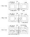
- the mark detector 57 in the case where the mark 2 is at a predetermined constant position such as a position which is within a printable area between images 3 printed on the web 1 and near one end in the width direction of the web 1, if the mark detector 57 is installed according to the mark position, the mark 2 can pass through the visual field of the mark detector 57. However, if the mark position is shifted widthwise from the constant position, the mark 2 will pass through a position shifted from the visual field of the mark detector 57 and therefore it will not be detected.
- the inventors have proposed a technique for controlling the width direction of the mark detector 57 according to the position in the width direction of a mark (see Japanese Patent Laid-Open Publication No. 2004-82279 ).
- the resolution of image data for plate making (or image data obtained by processing the image data for plate making) is converted to the resolution of the mark detector. And based on the converted image data, the position of a mark on a web is calculated, and based on the calculated mark position, the mark detector is moved to the mark position in the web width direction before the start of printing. This makes it possible to detect the mark on the web at the start of printing and to keep the web cutting-off position constant, whereby waste paper can be considerably reduced.
- the mark 2, or the edge portion 5 of the image 3 as the mark equivalent is a specified part in the traveling direction of the web 1
- the above-described incorrect mark recognition is caused by the mark detecting system that detects the mark or mark equivalent over all of the area in the traveling direction of the web 1 .
- such a system causes a great load to memory and arithmetic systems associated with mark recognition.
- the present invention has been made in view of the problems described above. Accordingly, it is the primary object of the present invention to provide a cutting-off control apparatus and method for a printing machine that are capable of preventing incorrect mark recognition and lightening a load to memory and arithmetic systems associated with the decision of mark detection, by previously recognizing the position in a web traveling direction of a mark relative to a printed image and limiting the detection of the mark by a mark detector to a specified place which corresponds to the recognized mark position.
- a cutting-off control apparatus for a printing machine which comprises five major components: (1) a sawing cylinder for cutting off a web which has images printed thereon; (2) a mark detector provided upstream of the sawing cylinder for detecting marks on the web; (3) a compensator roller for increasing or reducing a travel path length of the web, based on a difference between timing at which the web is cut off by the sawing cylinder and timing at which each of the marks is detected by the mark detector, to adjust a cutting-off position at which the web is cut off by the sawing cylinder; (4) positional relationship acquisition means for previously obtaining a positional relationship between a position in a web traveling direction of each of the marks to be printed on the web and a target cutting-off position of the web; and (5) detection timing control means for controlling mark detection timing so that the detection of each of the marks by the mark detector is performed during a specified period based on the positional relationship obtained by the positional relationship acquisition means.
- the compensator roller is controlled based on a difference between the timing at which the web is cut off by the sawing cylinder and the timing at which each of the marks is detected by the mark detector. Therefore, the compensator roll varies the travel path length of the web to adjust a cutting-off position at which the web is cut off.
- the positional relationship between the position in a web traveling direction of each of the marks to be printed on the web and a target cutting-off position of the web is obtained beforehand, and during a specified period based on the obtained positional relationship, the detection of each of the marks by the mark detector is performed. Therefore, since the mark detection timing is specified, the mark detection is performed only for specified areas on the web, and consequently, the possibility of incorrect mark recognition can be reduced. This can contribute to a reduction in waste paper. In addition, since a load to memory and arithmetic systems associated with the decision of mark detection can be lightened, the memory and arithmetic systems can be cheaply constructed.
- the above specified period is set to contain the timing at which a predetermined edge of the aforementioned mark passes through the detection area of the mark detector.
- the positional relationship acquisition means preferably includes image data storage means for storing first image data for plate making or second image data obtained by processing the first image data; and image data conversion means for converting a resolution of the first or second image data stored in the image data storage means to a resolution of the mark detector.
- the positional relationship acquisition means preferably calculates the position in the web traveling direction of each of the marks relative to the target cutting-off position, based on image data converted by the image data conversion means. Accordingly, the positional relationship, that is, the position in the web traveling direction of each of the marks relative to the target cutting-off position can be appropriately calculated, the mark detection timing can be suitably specified, and the detection of each of the marks by the mark detector can be made easier with reliability.
- the cutting-off control apparatus of the present invention may further include a reference signal generator for outputting a signal according to cutting-off timing at which the web is cut off by the sawing cylinder.
- the detection timing control means preferably sets the mark detection timing based on a signal from the reference signal generator and causes the mark detector to detect each of the marks at the set mark detection timing. Accordingly, since the setting of each of the marks detection timing can be appropriately performed, the detection of each of the marks by the mark detector can be made easier with reliability.
- the detection timing control means preferably shifts the set mark detection timing either back or forth and then causes the mark detector to detect the mark at the shifted mark detection timing. Accordingly, even in the case where the passing timing of each of the marks on the web is shifted due to expansion and contraction of the web, mark detection can be reliably performed.
- the cutting-off control apparatus of the present invention further includes mark position acquisition means for obtaining a position in a web width direction of each of the marks to be printed on the web; drive means for moving the mark detector in a width direction of the web; and detector position control means for controlling the drive means based on the position in the web width direction of each of the marks obtained by the mark position acquisition means, before start of printing. Accordingly, even when each of the marks is at any position in the web width direction, the mark detector is moved in the web width direction according to the position in the web width direction of each of the marks. Thus, it becomes possible to detect the mark printed on the web at the start of printing. This can contribute to a reduction in waste paper.
- each of the marks is preferably a specified portion of each of the images printed on the web. Accordingly, it is not necessary to print a dedicated mark outside an image (i.e., a blank outside the image), whereby the setting of marks required at the stage of plate making becomes unnecessary. In addition, when a blank outside an image is small, the mark setting will become fairly difficult, but such trouble can be avoided. On the other hand, there is a strong possibility of incorrectly recognizing marks, but as described above, the possibility of incorrect recognition can be reduced and therefore it becomes possible to recognize marks properly to suppress the occurrence of waste paper.
- a cutting-off control method for a printing machine which comprises a sawing cylinder for cutting off a web which has images printed thereon; a mark detector provided upstream of the sawing cylinder for detecting marks on the web; and a compensator roller for increasing or reducing a travel path length of the web, based on a difference between timing at which the web is cut off by the sawing cylinder and timing at which each of the marks is detected by the mark detector, to adjust a cutting-off position at which the web is cut off by the sawing cylinder.
- the method includes (1) a positional relationship acquisition step of previously obtaining a positional relationship between a position in a web traveling direction of each of the marks to be printed on the web and a target cutting-off position of the web; and (2) a mark detection timing control step of controlling mark detection timing so that the detection of each of the marks by the mark detector is performed during a specified period based on the positional relationship obtained in the positional relationship acquisition step.
- the compensator roller is controlled based on a difference between the timing at which the web is cut off by the sawing cylinder and the timing at which each of the marks is detected by the mark detector. Therefore, the compensator roll varies the travel path length of the web to adjust a cutting-off position at which the web is cut off.
- the positional relationship between the position in a web traveling direction of each of the marks to be printed on the web and a target cutting-off position of the web is obtained beforehand, and during a specified period based on the obtained positional relationship, the detection of each of the marks by the mark detector is performed. Therefore, since the mark detection timing is specified, the mark detection is performed only for specified areas on the web, and consequently, the possibility of incorrect mark recognition can be reduced. This can contribute to a reduction in waste paper. In addition, since a load to memory and arithmetic systems associated with the decision of mark detection can be lightened, the memory and arithmetic systems can be cheaply constructed.
- the positional relationship acquisition step preferably includes an image data storage step of storing first image data for plate making or second image data obtained by processing the first image data; an image data conversion step of converting a resolution of the first or second image data stored in the image data storage step to a resolution of the mark detector; and a mark position calculation step of calculating the position in the web traveling direction of each of the marks relative to the target cutting-off position, based on image data converted by the image data conversion step. Accordingly, the positional relationship, that is, the position in the web traveling direction of each of the marks relative to the target cutting-off position can be appropriately calculated, the mark detection timing can be suitably specified, and the detection of each of the marks by the mark detector can be made easier with reliability.
- the printing machine preferably includes reference signal generator for outputting a signal according to cutting-off timing at which the web is cut off by the sawing cylinder.
- the detection timing control step preferably sets the mark detection timing based on a signal from the reference signal generator and causes the mark detector to detect each of the marks at the set mark detection timing. Accordingly, since the setting of the mark detection timing can be appropriately performed, the detection of each of the marks by the mark detector can be made easier with reliability.
- the detection timing control step preferably shifts the set mark detection timing either back or forth and then causes the mark detector to detect the mark at the shifted mark detection timing. Accordingly, even in the case where the passing timing of each of the marks on the web is shifted due to expansion and contraction of the web, mark detection can be reliably performed.
- the cutting-off control method of the present invention further includes a mark position acquisition step of obtaining a position in a web width direction of each of the marks to be printed on the web; and a detector position control step of moving the mark detector in a width direction of the web, based on the position in the web width direction of each of the marks obtained by the mark position acquisition step, before start of printing. Accordingly, even when each of the marks is at any position in the web width direction, the mark detector is moved in the web width direction according to the position in the web width direction of each of the marks. Thus, it becomes possible to detect the mark printed on the web at the start of printing. This can contribute to a reduction in waste paper.
- each of the marks is preferably a specified portion of each of the images printed on the web. Accordingly, it is not necessary to print a dedicated mark outside an image (i.e., a blank outside the image), whereby the setting of marks required at the stage of plate making becomes unnecessary. In addition, when a blank outside an image is small, the mark setting will become fairly difficult, but such trouble can be avoided. On the other hand, there is a strong possibility of incorrectly recognizing marks, but as described above, the possibility of incorrect recognition can be reduced and therefore it becomes possible to recognize marks properly to suppress the occurrence of waste paper.
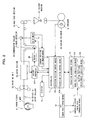
- FIG. 1 is a block diagram schematically showing a cutting-off control apparatus constructed in accordance with a preferred embodiment of the present invention.
- FIG. 2 is a block diagram schematically showing a printing machine to which the cutting-off control apparatus of the preferred embodiment is applied.
- a web 1 is conveyed from a paper feeder 51 through a series of guide rollers 52 and to a printing unit 53, in which images are transferred to the web 1. Thereafter, the web 1 is dried in a dryer section 54; is conveyed to a folding machine 56 through a web pass section 55; and is cut off in the web width direction by a sawing cylinder 60.
- a controller 13 drives a compensator roller 59 through a motor 58 so that the timing at which the web 1 is cut off by the sawing cylinder 60 and the timing at which the mark 2 is detected by the mark detector 6 coincide with each other or are within a predetermined difference.
- the compensator roll 59 functions to vary the travel path length of the web 1 to adjust the above-described timing difference, that is, a shift in the cutting-off position. In this manner, the web 1 can be cut off at a predetermined position.
- the cutting-off control apparatus also includes image data storage means 10, image data conversion means 11, mark position acquisition means 12A, positional relationship acquisition means 12B, detector position control means 13A, detection timing control means 13B, drive means 14 for the mark detector 6, a display 15, and current position estimation means 16 for estimating the current position of the mark detector 6.
- the image data storage means 10 is used for obtaining and storing image data, in which an image to be printed in the printing unit 53 originates [digital data for plate making which is used in a CTP system, or image data obtained by processing the image data in which an image to be printed in the printing unit 53 originates (e.g., digital data based on the CIP3/4-PPF standard)], online from a plate-making process.
- the preferred embodiment employs image data stored in a plate-making system which comprises DTP (Desktop Publishing), RIP (Raster Image Processor), and CTP (Computer to Plate).
- image data associated with the cutting-off control apparatus of the preferred embodiment is produced and stored by the RIP, the data storage section of which corresponds to the image data storage means 10.
- image data in which an image to be printed on the web 1 originates is stored in the image data storage means 10 with a resolution of about 2400 dpi, while digital data based on the CIP3/4-PPF standard is stored with a resolution of about 50 to 60 dpi.
- the image data conversion means 11 is used for converting the resolution 2400 dpi or 50 to 60 dpi of the above-described image data to the resolution 50.8 dpi of the mark detector 6 so that the resolution of the image data coincides with that of the mark detector 6.
- a conversion server for obtaining image data from RIP is employed as the image data conversion means 11.
- the minimum dimensions of the mark 2 that can be detected by the mark detector 6 of the preferred embodiment are 10 mm in width in the web width direction and 1 mm in length in the web flowing direction.
- a margin of 10 mm or greater is needed above the mark 2 (i.e., upstream of the mark 2) shown in FIG. 3.
- the resolution of the image data is converted to 50.8 dpi with the image conversion means 11. (In image data with a resolution of 50.8 dpi, a width equivalent to one pixel is 0.5 mm.)
- the mark position indication accuracy depends upon the visual field (detection area) of the mark detector 6, the mark position indication accuracy can be made coarser if the visual field of the mark detector 6 is wider.
- the mark detector 6 is able to find the mark 2 if it has an accuracy of 0.5 mm (i.e., the mark 2 enters the visual field of the mark detector 6).
- the mark position acquisition means 12A and positional relationship acquisition means 12B are provided as the constituent elements of a production management system 12.
- the detector position control means 13A and detection timing control means 13B are provided as the constituent elements of a controller 13.
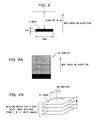
- the mark position acquisition means 12A functions to calculate (obtain) a mark position based on image data scaled down in the image data conversion means 11. More specifically, as shown in FIG. 4B, an image 31 scaled down in the image data conversion means 11 is matched with a template 30 such as that shown in FIG. 4A to calculate a mark position. Note that the matching is performed using the following sequential similarity detection algorithm.
- the mark 2 and the blank in front of the mark 2 shown in FIG. 3 are ideally shown by pixels.
- the black portion of the template 30 corresponds to the mark 2, while the white portion corresponds to the blank.
- the black portion has the maximum value of a pixel, while the white portion is made zero.
- the template 30 is placed on the upper left of an image converted; a difference between each pixel value of the template 30 and each pixel value at a position corresponding to the template 30 of the converted image 31 is calculated; and the differences are cumulated.
- this position in this case, it corresponds to the upper left of the converted image 31
- this position is recorded as a position where there is an image near to the template 30 (i.e., a position where the mark 2 is likely present).
- the position of the template 30 is shifted by one pixel, and the same operation is performed so that the template 30 can scan sequentially on the converted image 31.
- gray scale image black-and-white image
- This gray scale image is produced by stacking cyan (C), magenta (M), yellow (Y), and black (K) images given predetermined weights.
- the mark position acquisition means 12A functions to calculate a plurality of mark candidates which are usable as the mark 2.
- the mark position acquisition means 12A functions to select from the plurality of mark candidates the mark candidate nearest to the current position in the web width direction of the mark detector 6 estimated by the current position estimation means 16 described later, and also functions to set the selected mark candidate as an optimum mark, that is, a mark equivalent 2 (which is a specified portion of an image considered as a cut mark, and which will also be referred to simply as a mark).
- the position in the web width direction (position in the direction A) and position in the web traveling direction (position in the web flowing direction B) of the mark 2 can be obtained.
- the transversely center line CL of the image printing area normally coincides with the transversely center line of the web 1. Therefore, if the transversely center line CL is used as a reference line, the position in the web width direction of the mark 2 based on the image data, as it is, can be employed as the position in the web width direction of the mark 2 relative to the web 1.
- the position in the direction B of the mark 2 relative to the web 1 depends upon the marginal distance m from the end of the image area 3 to the cutting-off position (target cutting-off position). Therefore, since the position in the direction B of the mark 2 relative to the web 1 cannot be determined by only the distance l from the end of the image area 3 to the mark 2, it is necessary to calculate the sum of the distance l and marginal distance m .
- the cutting-off timing of the sawing cylinder 60 can be grasped by a reference pulse signal, from the encoder (rotary encoder) 61 as a reference signal generator, which is output according to the cutting-off timing.
- the reference pulse signal does not always synchronize with the cutting-off timing and has a phase difference (timing difference) peculiar to each printing machine. If this phase difference is caused to correspond to the position of the web 1, it can be expressed by d shown in FIG. 7.
- the positional difference L can be calculated from the position x in the direction B of the mark 2 relative to the web 1 (i.e., the distance from the cutting-off position to the mark 2) and the phase difference d.
- the distance x is the sum of the distance 1 and the marginal distance m .
- the distance 1 can be calculated from image data, while the marginal distance m can be calculated from the length in the direction B of the image area 3 obtained from image data and the cutting-off length.
- the distance x can be calculated from these distances l and m.
- the phase difference d can be obtained beforehand as a value peculiar to the printing machine. Accordingly, the positional difference L can also be calculated. Note that since the web 1 is normally traveling at a constant speed, the positional difference L, as itis, can be replaced with a temporal difference.
- the detection timing control means 13B outputs a gate signal Gs during a specified period containing the mark 2, and only during the period that the gate signal Gs is output, a detection signal from the mark detector 6 is taken in.
- the taken-in mark detection signal is stored in a memory device not shown, but the output period (specified period) of the gate signal Gs is set according to the capacity of the memory device.
- the output or input of the detection signal of the mark detector 6 is received in a shorter cycle than the thickness in the direction B of the mark 2 when calculated in terms of the distance in the traveling direction B of the web 1, and is stored in a memory device. For instance, if the capacity of the memory device corresponds to 10 cycles (i.e., 10 signals), the period of the gate signal Gs is set to the period of 10 cycles.
- the mark 2 will pass through the visual field of the mark detector 6 during the signal taking-in period and therefore normally the mark 2 can be detected without difficulty.
- the mark 2 is shifted due to expansion and contraction of the web 1, there is a possibility that the mark 2 cannot be detected during the period of the gate signal Gs.
- the gate signal Gs like Gs1 and Gs2 shown by two-dot chain lines in FIG. 7, by shifting the timing of the gate signal Gs back and forth by the amount of suitable cycles (e.g., 8 cycles) so that the gate signals Gs1 and Gs2 partially overlap with the original gate signal Gs, the mark 2 is detected.
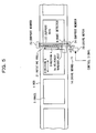
- the drive means 14 of the mark detector 6, as shown in FIG. 5, includes support members 23 and 24 disposed on both sides of the web 1; a support rail 22 fixed at both ends thereof to the support members 23 and 24 for supporting the movement in the web width direction of the mark detector 6; a rotating roll 21 provided in parallel to the support rail 22 and having a helical groove which meshes with a helically threaded hole 6a of the mark detector 6; and a drive motor 20 connected to the other end of the rotating roll 21 for rotating the rotating roll 21 in response to a control signal from the controller 13.
- rotation of the drive motor 20 causes the rotating roll 21 to rotate, and by the rotation of the rotating roll 21, the mark detector 6 is able to move between both ends of the web 1.
- the current position estimation means 16 is used for calculating, from the number of rotations of the drive motor 20 detected by a potentiometer not shown and the groove width of the helical groove of the rotating roll 21, how far the mark detector 6 is moved from a reference position (e.g., the position of the mark detector 6 show in FIG. 5), and estimating the current position in the web width direction of the mark detector 6.
- the detector position control means 13A functions dive motor 20 to move the mark detector 6 in the web width direction to a mark detectable position calculated by the mark position calculation means 12A. If the mark detector 6 is moved to the mark detectable position, then the control means 13 controls the drive means 14 (particularly, drive motor 20) so that the mark detector 6 is stopped at that position.
- the detector position control means 13A functions to display on a display 15 the distance between the above-describe mark position and the current position of the mark detector 6. For example, in FIG. 5, in the case where the above-described mark 2 passes through a position 30 cm above the mark detector 6, "+30 cm”, etc., are displayed on the display 15. In the case where the above-described mark 2 passes through a position 5 cm below the mark detector 6, "-5 cm”, etc., are displayed on the display 15. Accordingly, by watching the display 15, the operator can recognize which side and how far the mark detector 6 needs to be moved.
- the cutting-off control apparatus for the printing machine as the preferred embodiment is constructed as described above. Therefore, before the start of printing, the image data conversion means 11 converts the resolution of first image data for plate making stored in the image data storage means 10 (or second image data obtained by processing the first image data) to the resolution of the mark detector 6.
- the relative position acquisition means 12B calculates the position x in the direction B of the mark 2 relative to the web 1 (i.e., the distance from the cutting-off position to the mark 2).
- the detector position control means 13A drives the drive motor 20, and moves the mark detector 6 in the web width direction to a position at which the mark detector 6 can detect the mark. At this time, the distance between the position of the mark 2 and the current position of the mark detector 6 is displayed on the display 15.
- the detection timing control means 13B calculates the positional difference L between the reference pulse signal and the mark 2, from the position x in the direction B of the mark 2 relative to the web 1 obtained by the positional relationship acquisition means 12B and the phase difference d between the cutting-off timing and the reference pulse of the encoder. Based on the positional difference L , the gate signal Gs is output, and only during the period that the gate signal Gs is output, the detection signal of the mark detector 6 is taken in.
- a load to memory and arithmetic units associated with mark detection can be lightened. This can contribute to the cost suppression of these units.
- the mark 2 cannot be detected during the period of the gate signal Gs.
- the timing of the gate signal back and forth by the amount of suitable cycles (e.g., 8 cycles) so that the gate signals Gs1 and Gs2 partially overlap with the original gate signal Gs, the detection of the mark 2 is performed. Accordingly, the mark 2 can be reliably detected.
- a cut-off controller 62A controls a motor 58 to adjust the position of a compensator roller 59. As shown in FIG. 9, the adjustment of the position of the compensator roller 59 increases or reduces the travel path length of the web 1, whereby the cutting-off position of the web 1 is adjusted.
- the cutting-off control apparatus of the preferred embodiment is able to detect the marks on the web 1 at the start of printing, the cutting-off position of the web 1 can be kept constant at an appropriate position. Thus, waste paper can be considerably reduced.
- the mark 2 is shifted due to expansion and contraction of the web 1, there are cases where the mark 2 cannot be detected during the period of the gate signal Gs.
- the timing of the gate signal back and forth by the amount of suitable cycles (e.g., 8 cycles) so that the gate signals Gs1 and Gs2 partially overlap with the original gate signal Gs, the detection of the mark 2 is performed. Accordingly, the mark 2 can be reliably detected. Thus, the cutting-off position of the web 1 can be adjusted.
- the mark detector 6 is moved to the mark candidate nearest to the current position of the mark detector 6, so the time to move the mark detector 6 can be reduced.
- the preparation time up to the start of printing can be shortened.
- the distance between the current position of the mark detector 6 and the position of the mark 2 has been displayed on the display 15. Therefore, by watching the display 15, the operator can learn which side and how far the mark detector 6 needs to be moved. Therefore, in the case where the mark detector 6 can be manually moved in the web width direction, it is possible for the operator to move the mark detector 6 to a desired position by hand-operated.
- a mark equivalent which is a specified portion of an image considered as a cut mark
- a dedicated cut register mark may be employed as the mark 2.
- the controller 13 controls the drive means 14 to move the mark detector 6.
- an auxiliary cutting-off unit which is constructed so as to display the positional relationship between the current position of the mark detector 6 estimated by the current position estimation means 16 and the position of the mark 2, may be provided.
- this auxiliary unit the operator can be urged to move the mark detector 6, and the operator can also be notified how far the mark detector 6 needs to be moved. Accordingly, by watching the display 15, the operator is able to directly move the mark detector 6 before the start of printing.
- an auxiliary cutting-off unit which is constructed so as to schematically display the positional relationship between the current position of the mark detector 6 estimated by the current position estimation means 16 and the position of the mark 2, may be provided. Even in this case, the operator can be urged to move the mark detector 6, and by watching the display 15, the operator is able to directly move the mark detector 6 before the start of printing.
- the distance between the current position of the mark detector 6 and the position of the mark 2 may be displayed on the display 15.
Landscapes
- Inking, Control Or Cleaning Of Printing Machines (AREA)
- Controlling Rewinding, Feeding, Winding, Or Abnormalities Of Webs (AREA)
- Control Of Cutting Processes (AREA)
- Controlling Sheets Or Webs (AREA)
Applications Claiming Priority (1)
| Application Number | Priority Date | Filing Date | Title |
|---|---|---|---|
| JP2005365216A JP4891608B2 (ja) | 2005-12-19 | 2005-12-19 | 印刷機の断裁制御装置及び断裁制御方法 |
Publications (2)
| Publication Number | Publication Date |
|---|---|
| EP1798178A2 true EP1798178A2 (fr) | 2007-06-20 |
| EP1798178A3 EP1798178A3 (fr) | 2007-08-01 |
Family
ID=37805948
Family Applications (1)
| Application Number | Title | Priority Date | Filing Date |
|---|---|---|---|
| EP06025703A Withdrawn EP1798178A3 (fr) | 2005-12-19 | 2006-12-12 | Dispositif et procédé de contrôle de coupe pour une machine d'impression |
Country Status (4)
| Country | Link |
|---|---|
| US (1) | US7702414B2 (fr) |
| EP (1) | EP1798178A3 (fr) |
| JP (1) | JP4891608B2 (fr) |
| CN (1) | CN1986218B (fr) |
Cited By (4)
| Publication number | Priority date | Publication date | Assignee | Title |
|---|---|---|---|---|
| EP2322329A1 (fr) | 2009-11-13 | 2011-05-18 | Steinemann Technology AG | Procédé de laminage et procédé ainsi que dispositif de séparation de laminé |
| EP2481585A1 (fr) * | 2011-01-28 | 2012-08-01 | Müller Martini Holding AG | Dispositif et procédé de traitement d'une bande de matière d'impression pour produits d'impression |
| EP2258552A3 (fr) * | 2009-06-04 | 2012-09-26 | Baumer Innotec AG | Dispositif de détection d'un marquage sur un objet plat et procédé correspondant ainsi que dispositif destiné à la séparation de sections d'un objet plat |
| US9270850B2 (en) | 2013-01-25 | 2016-02-23 | Mueller Martini Holding Ag | Method for detecting and transmitting process-control data before and/or during a printing operation for the production of printed products in a printing press |
Families Citing this family (16)
| Publication number | Priority date | Publication date | Assignee | Title |
|---|---|---|---|---|
| ATE445872T1 (de) * | 2007-02-01 | 2009-10-15 | Abb Oy | Verfahren zur erstellung eines optimierten schnittplans für ein streifenförmiges material |
| JP5129648B2 (ja) * | 2008-05-13 | 2013-01-30 | 株式会社Pfu | 画像読取装置およびマーク検出方法 |
| KR101102628B1 (ko) | 2009-06-24 | 2012-01-04 | 방금필 | 디지털 제어가 가능한 인쇄수단이 구비된 골판지용 평판 타발시스템 |
| GB2494091B (en) | 2010-06-24 | 2016-03-16 | Hewlett Packard Development Co | Web press |
| WO2013046295A1 (fr) * | 2011-09-26 | 2013-04-04 | ホリゾン・インターナショナル株式会社 | Dispositif d'alimentation papier |
| WO2014209340A1 (fr) * | 2013-06-28 | 2014-12-31 | Hewlett-Packard Development Company, L.P. | Impression de trames imprimées en s'appuyant sur les longueurs de trame mesurées |
| CN103465623B (zh) * | 2013-08-01 | 2015-09-30 | 汕头东风印刷股份有限公司 | 一种卷筒印刷品裁切信号的自动检测方法 |
| JP6478686B2 (ja) * | 2015-02-12 | 2019-03-06 | キヤノン株式会社 | 画像処理装置、印刷装置、画像処理装置の制御方法、印刷装置の制御方法、及びプログラム |
| WO2016139056A1 (fr) * | 2015-03-03 | 2016-09-09 | Pfm Iberica Packaging Machinery S.A. | Dispositif permettant la compensation continue d'un étirement d'un film durant un tirage applicable sur des machines à emballer |
| JP7077532B2 (ja) * | 2017-05-15 | 2022-05-31 | セイコーエプソン株式会社 | 印刷装置、及び、印刷装置の制御方法 |
| CN111439616A (zh) * | 2020-03-23 | 2020-07-24 | 广德东威科技有限公司 | 一种收卷机及切割装置 |
| US11373071B2 (en) * | 2020-06-19 | 2022-06-28 | Datamax-O'neil Corporation | Methods and systems for operating a printing apparatus |
| US12466202B2 (en) * | 2021-03-05 | 2025-11-11 | Avery Dennison Retail Information Services Llc | Variable length cutting systems and methods |
| JP7632821B2 (ja) * | 2021-05-31 | 2025-02-19 | デュプロ精工株式会社 | 加工装置 |
| JP7767830B2 (ja) * | 2021-10-27 | 2025-11-12 | 沖電気工業株式会社 | 給紙制御装置、画像形成装置及び印刷システム |
| CN116039244B (zh) * | 2023-01-13 | 2023-05-26 | 安徽国瑞安全印务有限公司 | 一种印刷装置及印刷控制方法 |
Family Cites Families (13)
| Publication number | Priority date | Publication date | Assignee | Title |
|---|---|---|---|---|
| CH569558A5 (fr) * | 1972-09-22 | 1975-11-28 | Agfa Gevaert Ag | |
| US4366753A (en) * | 1980-04-11 | 1983-01-04 | Baldwin Korthe Web Controls, Inc. | Circumferential registration control system |
| US4415978A (en) * | 1981-04-14 | 1983-11-15 | Molins Machine Company, Inc. | Cut-to-mark cut-off control automated for splice and order change |
| JPS62230564A (ja) * | 1986-03-28 | 1987-10-09 | Konika Corp | センサ位置調整について改良した複写装置 |
| JPH0651545B2 (ja) * | 1990-07-04 | 1994-07-06 | 株式会社ニレコ | ウエブ加工制御装置 |
| JP3053670B2 (ja) | 1991-07-11 | 2000-06-19 | 大日本印刷株式会社 | 断裁位置制御装置 |
| JPH05330022A (ja) * | 1992-05-28 | 1993-12-14 | Dainippon Printing Co Ltd | ウェブの断裁見当制御装置 |
| JPH07232857A (ja) * | 1994-02-23 | 1995-09-05 | Orient Watch Co Ltd | 発券機 |
| CN1652938A (zh) * | 2002-03-25 | 2005-08-10 | 三菱重工业株式会社 | 能够控制伴随改变印刷速度的图像对准不良、切割对准不良和印刷密度波动的印刷机 |
| DE10221794A1 (de) * | 2002-05-15 | 2003-11-27 | Heidelberger Druckmasch Ag | Falzapparat in einer Rollenrotationsdruckmaschine |
| JP4216020B2 (ja) * | 2002-08-27 | 2009-01-28 | 三菱重工業株式会社 | 印刷機の断裁制御装置及び断裁補助装置 |
| JP2004082280A (ja) | 2002-08-27 | 2004-03-18 | Mitsubishi Heavy Ind Ltd | 印刷機の断裁制御装置 |
| DE10335887B4 (de) * | 2003-08-06 | 2007-11-08 | Man Roland Druckmaschinen Ag | Verfahren und Vorrichtung zum Regeln eines Schnittregisterfehlers und einer Bahnzugkraft einer Rollenrotationsdruckmaschine |
-
2005
- 2005-12-19 JP JP2005365216A patent/JP4891608B2/ja not_active Expired - Fee Related
-
2006
- 2006-12-12 EP EP06025703A patent/EP1798178A3/fr not_active Withdrawn
- 2006-12-18 US US11/612,065 patent/US7702414B2/en not_active Expired - Fee Related
- 2006-12-19 CN CN2006101686288A patent/CN1986218B/zh not_active Expired - Fee Related
Non-Patent Citations (1)
| Title |
|---|
| None |
Cited By (6)
| Publication number | Priority date | Publication date | Assignee | Title |
|---|---|---|---|---|
| EP2258552A3 (fr) * | 2009-06-04 | 2012-09-26 | Baumer Innotec AG | Dispositif de détection d'un marquage sur un objet plat et procédé correspondant ainsi que dispositif destiné à la séparation de sections d'un objet plat |
| EP2322329A1 (fr) | 2009-11-13 | 2011-05-18 | Steinemann Technology AG | Procédé de laminage et procédé ainsi que dispositif de séparation de laminé |
| DE102009053097A1 (de) | 2009-11-13 | 2011-07-21 | Steinemann Technology Ag | Laminierverfahren und Verfahren und Vorrichtung zum Trennen von Laminat |
| EP2481585A1 (fr) * | 2011-01-28 | 2012-08-01 | Müller Martini Holding AG | Dispositif et procédé de traitement d'une bande de matière d'impression pour produits d'impression |
| US9270850B2 (en) | 2013-01-25 | 2016-02-23 | Mueller Martini Holding Ag | Method for detecting and transmitting process-control data before and/or during a printing operation for the production of printed products in a printing press |
| EP2759405A3 (fr) * | 2013-01-25 | 2016-06-01 | Müller Martini Holding AG | Procédé d'enregistrement et de transmission de données de commande de processus avant et/ou dans un processus d'impression, dans la fabrication de produits imprimés dans une machine d'impression |
Also Published As
| Publication number | Publication date |
|---|---|
| US7702414B2 (en) | 2010-04-20 |
| JP2007167975A (ja) | 2007-07-05 |
| EP1798178A3 (fr) | 2007-08-01 |
| CN1986218A (zh) | 2007-06-27 |
| US20070144373A1 (en) | 2007-06-28 |
| JP4891608B2 (ja) | 2012-03-07 |
| CN1986218B (zh) | 2010-07-28 |
Similar Documents
| Publication | Publication Date | Title |
|---|---|---|
| US7702414B2 (en) | Cutting-off control apparatus and method for a printing machine | |
| EP1762387B1 (fr) | Presse équipée du dispositif de mesure des champs colotimétriques | |
| US11700341B2 (en) | Image inspection apparatus and misalignment measurement method | |
| US11113010B2 (en) | Printing using fiducial marks | |
| JP5371370B2 (ja) | プリンタおよび物体の移動検出方法 | |
| US20100080643A1 (en) | Printing press and operating method for the same | |
| US7027076B2 (en) | Media-position media sensor | |
| JP4216020B2 (ja) | 印刷機の断裁制御装置及び断裁補助装置 | |
| US20170259447A1 (en) | Post-processing apparatus and image forming apparatus for correcting deviation of punching position | |
| JP3790490B2 (ja) | 印刷物の品質管理装置及び印刷機 | |
| EP1080887A1 (fr) | Système de contrôle de la position d'une bande | |
| US6860662B2 (en) | Printing apparatus and method for processing a predetermined location on a printed sheet and a driver program therefor | |
| JP2008055782A (ja) | 印刷機 | |
| JP2002292831A (ja) | 見当絵柄抽出装置及び断裁位置制御装置並びに断裁位置制御システム | |
| JP3784631B2 (ja) | カラーチャート測定装置を備えた印刷装置、カラーチャート測定装置およびカラーチャート測定方法 | |
| US7559711B2 (en) | Method for controlling media feed in an imaging apparatus | |
| JP2017222139A (ja) | 印刷機の見当制御装置及び方法 | |
| US10897543B2 (en) | Image forming apparatus and method of controlling image forming apparatus | |
| EP1733880A2 (fr) | Appareil d'impression et méthode d'impression | |
| JP2008055783A (ja) | 印刷機 | |
| JPH06305218A (ja) | 電子写真装置の連係制御方法 | |
| JP2025117788A (ja) | シート検出装置、シート検出装置の制御方法及びプログラム |
Legal Events
| Date | Code | Title | Description |
|---|---|---|---|
| PUAI | Public reference made under article 153(3) epc to a published international application that has entered the european phase |
Free format text: ORIGINAL CODE: 0009012 |
|
| AK | Designated contracting states |
Kind code of ref document: A2 Designated state(s): AT BE BG CH CY CZ DE DK EE ES FI FR GB GR HU IE IS IT LI LT LU LV MC NL PL PT RO SE SI SK TR |
|
| AX | Request for extension of the european patent |
Extension state: AL BA HR MK YU |
|
| PUAL | Search report despatched |
Free format text: ORIGINAL CODE: 0009013 |
|
| AK | Designated contracting states |
Kind code of ref document: A3 Designated state(s): AT BE BG CH CY CZ DE DK EE ES FI FR GB GR HU IE IS IT LI LT LU LV MC NL PL PT RO SE SI SK TR |
|
| AX | Request for extension of the european patent |
Extension state: AL BA HR MK YU |
|
| RIC1 | Information provided on ipc code assigned before grant |
Ipc: B41F 33/00 20060101ALI20070627BHEP Ipc: B65H 35/04 20060101ALI20070627BHEP Ipc: B65H 23/188 20060101ALI20070627BHEP Ipc: B65H 23/04 20060101AFI20070309BHEP |
|
| 17P | Request for examination filed |
Effective date: 20080115 |
|
| AKX | Designation fees paid |
Designated state(s): DE |
|
| 17Q | First examination report despatched |
Effective date: 20091027 |
|
| RAP1 | Party data changed (applicant data changed or rights of an application transferred) |
Owner name: MITSUBISHI HEAVY INDUSTRIES PRINTING & PACKING MAC |
|
| RAP1 | Party data changed (applicant data changed or rights of an application transferred) |
Owner name: MITSUBISHI HEAVY INDUSTRIES PRINTING & PACKAGING M |
|
| STAA | Information on the status of an ep patent application or granted ep patent |
Free format text: STATUS: THE APPLICATION IS DEEMED TO BE WITHDRAWN |
|
| 18D | Application deemed to be withdrawn |
Effective date: 20110701 |