EP1798332A1 - Procédé et dispositif de dégazage den matériau fluide ou pâteux - Google Patents
Procédé et dispositif de dégazage den matériau fluide ou pâteux Download PDFInfo
- Publication number
- EP1798332A1 EP1798332A1 EP06122722A EP06122722A EP1798332A1 EP 1798332 A1 EP1798332 A1 EP 1798332A1 EP 06122722 A EP06122722 A EP 06122722A EP 06122722 A EP06122722 A EP 06122722A EP 1798332 A1 EP1798332 A1 EP 1798332A1
- Authority
- EP
- European Patent Office
- Prior art keywords
- medium
- degassed
- degassing
- gas
- volume flow
- Prior art date
- Legal status (The legal status is an assumption and is not a legal conclusion. Google has not performed a legal analysis and makes no representation as to the accuracy of the status listed.)
- Ceased
Links
- 238000007872 degassing Methods 0.000 title claims abstract description 27
- 238000000034 method Methods 0.000 title claims abstract description 20
- 239000007788 liquid Substances 0.000 title claims abstract description 5
- 239000011248 coating agent Substances 0.000 claims abstract description 35
- 238000000576 coating method Methods 0.000 claims abstract description 35
- 239000011111 cardboard Substances 0.000 claims abstract description 9
- 239000006260 foam Substances 0.000 claims abstract description 9
- 239000011087 paperboard Substances 0.000 claims abstract description 8
- 235000011837 pasties Nutrition 0.000 claims abstract description 4
- 238000009849 vacuum degassing Methods 0.000 claims abstract description 4
- 238000007599 discharging Methods 0.000 abstract 2
- 239000000123 paper Substances 0.000 description 5
- 238000007766 curtain coating Methods 0.000 description 4
- 238000009434 installation Methods 0.000 description 4
- 239000003086 colorant Substances 0.000 description 3
- 238000013022 venting Methods 0.000 description 3
- JTJMJGYZQZDUJJ-UHFFFAOYSA-N phencyclidine Chemical class C1CCCCN1C1(C=2C=CC=CC=2)CCCCC1 JTJMJGYZQZDUJJ-UHFFFAOYSA-N 0.000 description 2
- 239000000049 pigment Substances 0.000 description 2
- 238000000926 separation method Methods 0.000 description 2
- 239000000758 substrate Substances 0.000 description 2
- 239000010409 thin film Substances 0.000 description 2
- 230000003750 conditioning effect Effects 0.000 description 1
- 230000007547 defect Effects 0.000 description 1
- 238000013461 design Methods 0.000 description 1
- 239000006185 dispersion Substances 0.000 description 1
- 230000000694 effects Effects 0.000 description 1
- 238000002474 experimental method Methods 0.000 description 1
- 239000010408 film Substances 0.000 description 1
- 238000007730 finishing process Methods 0.000 description 1
- 238000002309 gasification Methods 0.000 description 1
- 238000012423 maintenance Methods 0.000 description 1
- 238000004519 manufacturing process Methods 0.000 description 1
- 230000003287 optical effect Effects 0.000 description 1
- 230000010349 pulsation Effects 0.000 description 1
- 239000007787 solid Substances 0.000 description 1
- 238000009423 ventilation Methods 0.000 description 1
- 230000000007 visual effect Effects 0.000 description 1
Images
Classifications
-
- D—TEXTILES; PAPER
- D21—PAPER-MAKING; PRODUCTION OF CELLULOSE
- D21D—TREATMENT OF THE MATERIALS BEFORE PASSING TO THE PAPER-MAKING MACHINE
- D21D5/00—Purification of the pulp suspension by mechanical means; Apparatus therefor
- D21D5/26—De-aeration of paper stock
-
- B—PERFORMING OPERATIONS; TRANSPORTING
- B01—PHYSICAL OR CHEMICAL PROCESSES OR APPARATUS IN GENERAL
- B01D—SEPARATION
- B01D19/00—Degasification of liquids
- B01D19/0036—Flash degasification
-
- B—PERFORMING OPERATIONS; TRANSPORTING
- B01—PHYSICAL OR CHEMICAL PROCESSES OR APPARATUS IN GENERAL
- B01D—SEPARATION
- B01D19/00—Degasification of liquids
- B01D19/0042—Degasification of liquids modifying the liquid flow
- B01D19/0052—Degasification of liquids modifying the liquid flow in rotating vessels, vessels containing movable parts or in which centrifugal movement is caused
- B01D19/0057—Degasification of liquids modifying the liquid flow in rotating vessels, vessels containing movable parts or in which centrifugal movement is caused the centrifugal movement being caused by a vortex, e.g. using a cyclone, or by a tangential inlet
-
- D—TEXTILES; PAPER
- D21—PAPER-MAKING; PRODUCTION OF CELLULOSE
- D21H—PULP COMPOSITIONS; PREPARATION THEREOF NOT COVERED BY SUBCLASSES D21C OR D21D; IMPREGNATING OR COATING OF PAPER; TREATMENT OF FINISHED PAPER NOT COVERED BY CLASS B31 OR SUBCLASS D21G; PAPER NOT OTHERWISE PROVIDED FOR
- D21H23/00—Processes or apparatus for adding material to the pulp or to the paper
- D21H23/02—Processes or apparatus for adding material to the pulp or to the paper characterised by the manner in which substances are added
- D21H23/22—Addition to the formed paper
- D21H23/46—Pouring or allowing the fluid to flow in a continuous stream on to the surface, the entire stream being carried away by the paper
- D21H23/48—Curtain coaters
Definitions
- the invention relates to a method and a device, in particular a coating color for coating paper or cardboard, wherein the medium to be degassed is introduced into a vacuum vessel and thereby largely degassed, wherein gas and the largely degassed medium are discharged separately.
- the medium is, in particular, a coating color with which, in particular, a paper, cardboard or other fibrous web is to be removed during its production or finishing process for the purpose of improving its printability and optical properties.
- the coating color generally consists of aqueous pigment dispersion which is applied as uniformly as possible with a certain film thickness and then dried.
- free-jet nozzle applicators mechanical deaerators that operate on an eddy-current or cyclone principle are often used.
- This gas bubbles can be removed with a size of 200 microns. Smaller gas bubbles stay in the coating color or are still reduced by the relatively high shear forces in the cyclone, so they are no longer disturbing in the free jet.
- the efficiency of the cyclone gasifier is about 40 to 70%, so that even after passing through the degasser gas or air is included in the coating color. Since very large gas bubbles are removed one hundred percent and only these large bubbles interfere with the free jet application, the efficiency is sufficient for this type of coating.
- Zyklonentgaser are also known from the patent funds and indeed for example from the EP-A1 0618012 and the US 5,080,792 .
- the medium to be degassed is introduced eccentrically into a stationary container, so that adjusts a swirling motion of the medium in the interior of the container.
- the centrifugal force caused by this swirling movement by utilizing the density differences between the medium to be degassed on the one hand and the gas enclosed therein on the other hand, ensures separation of medium and gas.
- fibrous webs are to be coated by means of the curtain coating method.
- the application medium in the amount in which it should also remain on the fibrous web, in free fall, that is applied in the form of a free-falling and closed curtain on the fibrous web.
- the requirements for this are Application medium (coating color) extremely high, which is why a particularly largely degassed medium is necessary.
- the operating principle of this degasser is based on the generation of thin layers of medium to be degassed, which run through the vacuum degasser on the longest possible way.
- the absolute pressure in the vacuum degasser is between 10 and 300 mbar, in particular between 30 and 100 mbar.
- the Applicant is known a device in which a degassing at least one further downstream, wherein all successively and / or mutually parallel degassing are vacuum degasser.
- the degree of separation of the one vacuum degasser or the plurality of vacuum degassers is not sufficient to ensure optimum degassing or venting.
- the invention is therefore based on the object to provide a method and an apparatus with which an even better degassing is possible.
- the object is achieved with a method according to claim 1 in such a way that after the degassing in per se known Vacuum container the already largely degassed medium is subjected to further degassing in a known cyclone gasifier, wherein a resulting gas-containing volume flow or foam and a volume of degassed medium are also removed separately.
- the inventors have recognized that by combining vacuum venting and cyclone venting, the gas content in the coating color can be reduced so that in the end no visible disturbances caused by a gas content are present on the web surface.
- the Zyklonentgaser requires a certain differential pressure in order to achieve an optimal result, this should be between 1 and 4 bar, preferably between 1.5 and 2.5 bar.
- the gas bubbles separated in the cyclone gasification are removed via a foam line to the outside.
- the volume flow at this gas-containing fraction is less than 15% of the total volume flow, in particular in the range between 1 and 10%. This separated volume flow can be discarded, as well as returned to a working and collecting tank to subject him again in the cycle said degassing.
- the substantially gas-free medium produced in this way can now be fed to a coating device downstream of the cyclone gasifier.
- a curtain coater as a coating device. Namely, curtain coating is a very easy-to-use and application medium-saving application method, because no device parts of the coater touch the web and only so much application medium is to be applied as to remain on the web or substrate.
- high-viscosity application media can be applied to a substrate or to a running paper, board or other web by means of curtain coating.
- the object of the invention is also achieved with a device for carrying out the method.
- a vacuum degasser known per se is followed by a cyclone gas, which is also known per se.
- the cyclone gasifier has an inlet for the further to be degassed medium, a discharge line for a resulting gas-containing volume flow, and an outlet and a discharge line for the substantially gas-free or degassed medium.
- a further advantageous embodiment of the device may be that the Cyclone gas is divided into at least one of the medium to be degassed through flow unit.
- the advantage of more than one unit is that the flow through the cyclone gas can be better distributed. It is thus possible to design these for different flow volumes, for example 10 l / min, 5 l / min and 2.5 l / min, as well as for equal flow volumes. For equal flow volumes identical container parts, better spare parts inventory and maintenance are to be regarded as an advantage.
- the individual units preferably four units, with the same or different flow volumes are flowed through in parallel and can be switched on and off by valves depending on the flow. This achieves a high flexibility in the flow and can still achieve the necessary differential pressure between the inlet and outlet of the cyclone gasifier.
- Another advantageous solution may be to install a plurality of cyclone gas generators in series after the vacuum degasser. As a result, the degassing effect is further improved. Alternately or additionally, it is also possible to provide multiple vacuum degasser.
- the cyclone gas provided or the last cyclone gas in series can be connected via a discharge line for the degassed medium with a medium feed a directly downstream coating device, in particular a curtain commissioned work.
- the advantage of the invention consists in a very extensive ventilation of the existing medium. For coating colors are no visible disturbances on the Track surface, resulting in a higher order quality than previously achieved.
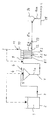
- FIG. 1 shows, roughly schematically, the method sequence or a device according to the invention for degassing
- FIG. 1 shows how a liquid to pasty medium 1 is degassed.
- it is an application or coating medium in the form of a high-viscosity coating color for finishing a running paper or board web.
- the apparatus shown has a working container 2, in which the medium 1 to be degassed is stored.
- the medium 1 is first fed via a line 3 in the direction of the arrow to a first degasser, namely a vacuum degasser 4.
- An inlet 5 for the medium 1 to be degassed and, in addition, a vacuum connection or vacuum generator 6 are provided on the lid of the vacuum degasser 4.
- the vacuum degasser 4 may have various shapes and internal configurations for the purpose of achieving an extended passage and the achievement of a thin film to be degassed. However, the geometry of the vacuum container is not increased compared to conventional vacuum degassers. Possible installations are in the form of a centrally arranged, vertical drive shaft with at least one coaxially arranged turntable with rotational speeds of about 2500 1 / min, or the arrangement of Hochrotationszerstäuberdüsen with speeds up to 20000 1 / min for feeding the medium, the installation of run-offs also in cascade form and the like, to which, however, will not be discussed here.
- the absolute pressure in the vacuum degasser is set to about 10 to 300 mbar, preferably 30 to 100 mbar. At a temperature of 30 to 50 ° C of the medium 1, the degassing then takes place, wherein an already largely degassed medium 1a. receives. This already largely degassed medium 1a is fed via a discharge line 7 in the direction of the arrow to a vacuum degasser 4 (or in the case of equally possible several vacuum containers, the last of the containers) downstream cyclone gas 8.
- the supply takes place tangentially, whereby the specific lighter gas or the air contained in the center of the induced swirl can collect and can be easily dissipated.
- the cyclone gasifier 8 has a tangential inlet 9 for the further to be degassed medium 1a, a discharge line 10 for a gas-containing volumetric flow 11 or foam, and an outlet 12 and a discharge line 13 for the almost completely or greatly degassed or practical gas-free medium 1b.
- this degasser 8 is flowed through in parallel in a plurality of units through which flow in parallel, in the example, four pieces, of the medium 1a to be degassed.
- the units are with 8.1; 8.2; 8.3 and 8.4 or 8.n for possible further units.
- the individual units or individual cyclones 8.1 to 8.n can then be switched on or off depending on the current flow.
- This configuration achieves more flexibility in the flow and can nevertheless achieve the necessary differential pressure between inlet and outlet of the cyclone gasifier of about 2 bar.
- the units 8.1 to 8n through which the gas to be degassed 1a flows are Therefore in each unit desired equal, but also different flow volume adjustable.
- the first unit 8.1 are in the example 10 l / min
- the second unit 8.3 are 5 l / min
- in the other units 8.3 and 8.4 are each 2.5 l / min by not marked with valves on and off, thereby for the immediately downstream curtain applicator 14 a target flow of 15 l / min is achieved.
- this embodiment allows the pressure difference to be set for a wide range of viscosities.
- the term "practically gas-free” means that realistically no 100% degassing is possible. Lowest residual amounts may still be contained, but are so low by the inventive additional installation of at least one cyclone gaser 8 that it is no longer due to gas on the surface of a coated with the applicator 14 and its output curtain 14a fibrous web 15 of paper or cardboard Defects comes.
- pumps, filters and also pulsation dampers are incorporated in the process sequence or the device provided for this purpose, which are not shown here separately because of their prominence. Likewise, the drawing of the individual inlet and shut-off valves was omitted.
Landscapes
- Chemical & Material Sciences (AREA)
- Chemical Kinetics & Catalysis (AREA)
- Engineering & Computer Science (AREA)
- Mechanical Engineering (AREA)
- Paper (AREA)
Applications Claiming Priority (1)
| Application Number | Priority Date | Filing Date | Title |
|---|---|---|---|
| DE200510060847 DE102005060847A1 (de) | 2005-12-16 | 2005-12-16 | Verfahren und Vorrichtung zum Entgasen eines flüssigen bis pastösen Mediums |
Publications (1)
| Publication Number | Publication Date |
|---|---|
| EP1798332A1 true EP1798332A1 (fr) | 2007-06-20 |
Family
ID=37770368
Family Applications (1)
| Application Number | Title | Priority Date | Filing Date |
|---|---|---|---|
| EP06122722A Ceased EP1798332A1 (fr) | 2005-12-16 | 2006-10-23 | Procédé et dispositif de dégazage den matériau fluide ou pâteux |
Country Status (2)
| Country | Link |
|---|---|
| EP (1) | EP1798332A1 (fr) |
| DE (1) | DE102005060847A1 (fr) |
Citations (2)
| Publication number | Priority date | Publication date | Assignee | Title |
|---|---|---|---|---|
| US5149341A (en) * | 1991-08-23 | 1992-09-22 | Taylor John A | Paper coater skip prevention and deaeration apparatus and method |
| DE10352807A1 (de) * | 2003-11-12 | 2005-06-23 | Voith Paper Patent Gmbh | Auftragsvorrichtung |
-
2005
- 2005-12-16 DE DE200510060847 patent/DE102005060847A1/de not_active Withdrawn
-
2006
- 2006-10-23 EP EP06122722A patent/EP1798332A1/fr not_active Ceased
Patent Citations (2)
| Publication number | Priority date | Publication date | Assignee | Title |
|---|---|---|---|---|
| US5149341A (en) * | 1991-08-23 | 1992-09-22 | Taylor John A | Paper coater skip prevention and deaeration apparatus and method |
| DE10352807A1 (de) * | 2003-11-12 | 2005-06-23 | Voith Paper Patent Gmbh | Auftragsvorrichtung |
Also Published As
| Publication number | Publication date |
|---|---|
| DE102005060847A1 (de) | 2007-06-28 |
Similar Documents
| Publication | Publication Date | Title |
|---|---|---|
| DE69213828T2 (de) | Verfahren zur Herstellung von Streichdruckpapier | |
| DE68913551T2 (de) | Vorrichtung und verfahren zur beschichtung von papier und dergleichen. | |
| DE69409067T2 (de) | Vorrichtung zum Entgasen von Flüssigkeiten | |
| DE1642787A1 (de) | Verfahren zum Abscheiden von Fremdkoerpern aus einer fliessfaehigen Suspension,insbesondere aus einer waessrigen Aufschlaemmung von Faserstoffen fuer die Papierherstellung und Fliehkraft-Abscheider zur Durchfuehrung des Verfahrens | |
| EP0554285A1 (fr) | Procede pour la recuperation de matieres premieres a partir de la boue des eaux residuelles de l'industrie du papier traitees par le procede mecanique. | |
| DE102008000451A1 (de) | Streichstation | |
| AT509528B1 (de) | Verfahren zum beschichten einer faserbahn mit einem vorhangbeschichter | |
| DE69218615T2 (de) | Ein papierbeschichtungssystem und verfahren | |
| DE68910129T2 (de) | Vorrichtung und verfahren zur beseitigung von leichtem material aus einer fasersuspension. | |
| EP1811084A2 (fr) | Procédé et dispositif de dégazage d'une composition fluide ou pâteuse | |
| DE1937397C3 (de) | Verfahren zum Trennen eines Gemisches aus mehreren flüssigen Phasen | |
| WO2008028722A1 (fr) | Dispositif de dÉgazage | |
| DE102005060846A1 (de) | Verfahren und Vorrichtung zum Entgasen eines flüssigen bis pastösen Mediums, insbesondere einer Streichfarbe | |
| CH712233A2 (de) | Verfahren zur Herstellung von Dispersionen mit definierter Partikelgrösse. | |
| DE102019117048A1 (de) | Formgebungsmaschine mit einem Hydrauliksystem | |
| EP1798332A1 (fr) | Procédé et dispositif de dégazage den matériau fluide ou pâteux | |
| EP1798333B1 (fr) | Appareil pour dégazer une substance liquide ou pâteuse, en particulier une couleur d'enduction | |
| EP0466744B2 (fr) | Procede pour separer glycerine en utilisant en tant qu'adjuvant de coalescence un lit de fibres | |
| EP1533418A2 (fr) | Dispositif d'enduction | |
| EP2864018B1 (fr) | Filtration en dérivation | |
| DE19845536C2 (de) | Verfahren zur Entfernung von Störstoffen aus einer wässrigen papierfaserhaltigen Suspension | |
| DD296262A5 (de) | Verfahren und vorrichtung zur behandlung eines filtrates | |
| DE19923600A1 (de) | Verfahren zur Aufbereitung von mineralischen Rohstoffen, insbesondere von Steinkohle | |
| EP4380711A1 (fr) | Dispositif et procédé pour séparer des mélanges de fluides | |
| DE102005060850A1 (de) | Vorrichtung und Verfahren zum Entgasen eines flüssigen bis pastösen Mediums, insbesondere einer Streichfarbe |
Legal Events
| Date | Code | Title | Description |
|---|---|---|---|
| PUAI | Public reference made under article 153(3) epc to a published international application that has entered the european phase |
Free format text: ORIGINAL CODE: 0009012 |
|
| AK | Designated contracting states |
Kind code of ref document: A1 Designated state(s): AT BE BG CH CY CZ DE DK EE ES FI FR GB GR HU IE IS IT LI LT LU LV MC NL PL PT RO SE SI SK TR |
|
| AX | Request for extension of the european patent |
Extension state: AL BA HR MK YU |
|
| 17P | Request for examination filed |
Effective date: 20071220 |
|
| AKX | Designation fees paid |
Designated state(s): AT BE BG CH CY CZ DE DK EE ES FI FR GB GR HU IE IS IT LI LT LU LV MC NL PL PT RO SE SI SK TR |
|
| 17Q | First examination report despatched |
Effective date: 20100423 |
|
| STAA | Information on the status of an ep patent application or granted ep patent |
Free format text: STATUS: THE APPLICATION HAS BEEN REFUSED |
|
| 18R | Application refused |
Effective date: 20110206 |