EP1798362A2 - Fixation d'un profilé de cadre d'un cadre de porte ou de fenêtre dans une ouverture dans un mur d'un bâtiment - Google Patents
Fixation d'un profilé de cadre d'un cadre de porte ou de fenêtre dans une ouverture dans un mur d'un bâtiment Download PDFInfo
- Publication number
- EP1798362A2 EP1798362A2 EP06026004A EP06026004A EP1798362A2 EP 1798362 A2 EP1798362 A2 EP 1798362A2 EP 06026004 A EP06026004 A EP 06026004A EP 06026004 A EP06026004 A EP 06026004A EP 1798362 A2 EP1798362 A2 EP 1798362A2
- Authority
- EP
- European Patent Office
- Prior art keywords
- screw
- frame profile
- profile
- frame
- attachment according
- Prior art date
- Legal status (The legal status is an assumption and is not a legal conclusion. Google has not performed a legal analysis and makes no representation as to the accuracy of the status listed.)
- Withdrawn
Links
Images

Classifications
-
- E—FIXED CONSTRUCTIONS
- E06—DOORS, WINDOWS, SHUTTERS, OR ROLLER BLINDS IN GENERAL; LADDERS
- E06B—FIXED OR MOVABLE CLOSURES FOR OPENINGS IN BUILDINGS, VEHICLES, FENCES OR LIKE ENCLOSURES IN GENERAL, e.g. DOORS, WINDOWS, BLINDS, GATES
- E06B1/00—Border constructions of openings in walls, floors, or ceilings; Frames to be rigidly mounted in such openings
- E06B1/56—Fastening frames to the border of openings or to similar contiguous frames
- E06B1/60—Fastening frames to the border of openings or to similar contiguous frames by mechanical means, e.g. anchoring means
-
- F—MECHANICAL ENGINEERING; LIGHTING; HEATING; WEAPONS; BLASTING
- F16—ENGINEERING ELEMENTS AND UNITS; GENERAL MEASURES FOR PRODUCING AND MAINTAINING EFFECTIVE FUNCTIONING OF MACHINES OR INSTALLATIONS; THERMAL INSULATION IN GENERAL
- F16B—DEVICES FOR FASTENING OR SECURING CONSTRUCTIONAL ELEMENTS OR MACHINE PARTS TOGETHER, e.g. NAILS, BOLTS, CIRCLIPS, CLAMPS, CLIPS OR WEDGES; JOINTS OR JOINTING
- F16B5/00—Joining sheets or plates, e.g. panels, to one another or to strips or bars parallel to them
- F16B5/02—Joining sheets or plates, e.g. panels, to one another or to strips or bars parallel to them by means of fastening members using screw-thread
- F16B5/0283—Joining sheets or plates, e.g. panels, to one another or to strips or bars parallel to them by means of fastening members using screw-thread with an externally threaded sleeve around the neck or the head of the screw-threaded element for adjustably fastening a plate or frame or the like to a fixed element
-
- E—FIXED CONSTRUCTIONS
- E06—DOORS, WINDOWS, SHUTTERS, OR ROLLER BLINDS IN GENERAL; LADDERS
- E06B—FIXED OR MOVABLE CLOSURES FOR OPENINGS IN BUILDINGS, VEHICLES, FENCES OR LIKE ENCLOSURES IN GENERAL, e.g. DOORS, WINDOWS, BLINDS, GATES
- E06B1/00—Border constructions of openings in walls, floors, or ceilings; Frames to be rigidly mounted in such openings
- E06B1/56—Fastening frames to the border of openings or to similar contiguous frames
- E06B1/60—Fastening frames to the border of openings or to similar contiguous frames by mechanical means, e.g. anchoring means
- E06B1/6084—Mounting frames elastically, e.g. with springs or other elastic material, between the wall and the frame
Definitions
- the invention relates to the attachment of a frame profile of a door or a window frame in a wall opening of a building.
- DE 200 18 425 U1 refers to a designated screw.
- this is provided with circumferential over the circumference webs with ramp-like cross-sectional shape.
- a disadvantage of this invention is that when screwing the screw, the hollow profile is deformed damaging in the bore, that the contact surfaces of the collar-like webs at the edge of the profile wall are very small, and that normally only one wall of the hollow profile fits snugly against a collar of the screw.
- the screw can not be disassembled without damaging the hollow profile.
- DE 299 08 054 U1 shows the adjustable attachment of a hollow profile to a building.
- a clamping sleeve on which the hollow profile is supported on the building, axially penetrated by a bolt which is anchored in a bore in the building, and frictionally abuts with a rubber-elastic sheath on the inner lateral surface of the threaded sleeve.
- the adjustment is made by turning the threaded sleeve connected to the hollow profile clamping sleeve.
- the bolt merely provides a safeguard against movement of the hollow profile in the plane lying normal to the axis of the clamping sleeve.
- a disadvantage of this attachment method is especially the high material and labor required.
- DE 20 2004 004 893 U1 relates to a screw for anchoring a provided with a reinforcing metal profile plastic profile on a substructure.
- the screw In the longitudinal profile of the screw extending in the hollow profile, the latter is provided with a circumferential web around the circumference with a ramp-like cross-sectional shape. When screwing in the screw this web slides through a hole in the hollow profile, when unscrewing comes his steeper flank on the hollow profile to concern. This achieves an adjustment function.
- the screw can be in the area between circumferential web and
- Screw head be surrounded with a plastic sleeve, which rests on the, or the surrounding holes in the hollow profile on friction, and thus causes a better holding action and backlash.
- the inventor has taken on the task of improving the attachment of the frame profiles of a door or a window in a wall opening of a building to the effect that relative dimensional or positional changes between the parts to be fastened, which, for example, by temperature fluctuations or Shocks can occur, leading to no damage.
- the attachment should be so executable that the correspondingly fixed frame profile is adjustable in its position on the building, the frame profile is not damaged by the attachment and the attachment is free of damage disassembled.
- the required fasteners should fit for as many different frame profile shapes.
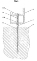
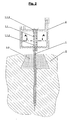
- a screw 1 for anchoring and adjusting a frame profile 2 on a base 3 consists of a cylindrical shaft at the Einschraubend Scheme a thread and at the other end a head is formed with a tool engagement. Furthermore, the cylindrical shaft is overmolded at most of its length with a plastic part 1.1 which has a plurality of webs 1.1.1 running in the longitudinal direction of the screw and a plurality of sawtooth-like elevations 1.1.2. The plastic part 1.1 is firmly connected to the cylindrical shaft 1.1 of the screw 1.
- the bore in the base 3 is designed as a stepped bore such that the shallower region of the bore is designed with a larger diameter than the outer diameter of the screw 1 in this longitudinal region.
- the frame profile 2 is given a greater elastic range of motion in the plane lying normal to the screw axis, since the shank of the screw thus obtains a long free bending area.
- the area between masonry and frame profile is normally filled with a soft elastic, thermally insulating insulation material in a later step. The usual materials are so soft that the restriction of the bending ability of the shank of the screw caused by them can be neglected.
- This construction compensates for the loss of thermally effective wall thickness in the region of the window frame which is relatively thin compared to the wall when a window frame is fastened. It is advantageous to execute the groove in the ground with an inwardly widening cross-sectional surface area, since this ensures that the inserted insulation strip can not fall out.
- the groove is not cut at the construction site, but it is already bricks for the wall opening industrially prefabricated. These bricks can then already be provided with an insulating strip.
- the invention is then particularly advantageous to apply when the frame profile 2 to be anchored is a hollow profile.
Landscapes
- Engineering & Computer Science (AREA)
- General Engineering & Computer Science (AREA)
- Mechanical Engineering (AREA)
- Civil Engineering (AREA)
- Structural Engineering (AREA)
- Connection Of Plates (AREA)
- Dowels (AREA)
- Door And Window Frames Mounted To Openings (AREA)
Applications Claiming Priority (1)
| Application Number | Priority Date | Filing Date | Title |
|---|---|---|---|
| AT20122005A AT502994B1 (de) | 2005-12-16 | 2005-12-16 | Schraube zur elastischen verankerung eines teiles an einem unterbau |
Publications (2)
| Publication Number | Publication Date |
|---|---|
| EP1798362A2 true EP1798362A2 (fr) | 2007-06-20 |
| EP1798362A3 EP1798362A3 (fr) | 2008-06-04 |
Family
ID=37893122
Family Applications (1)
| Application Number | Title | Priority Date | Filing Date |
|---|---|---|---|
| EP06026004A Withdrawn EP1798362A3 (fr) | 2005-12-16 | 2006-12-15 | Fixation d'un profilé de cadre d'un cadre de porte ou de fenêtre dans une ouverture dans un mur d'un bâtiment |
Country Status (2)
| Country | Link |
|---|---|
| EP (1) | EP1798362A3 (fr) |
| AT (1) | AT502994B1 (fr) |
Family Cites Families (4)
| Publication number | Priority date | Publication date | Assignee | Title |
|---|---|---|---|---|
| DE3340666A1 (de) * | 1983-11-10 | 1985-05-30 | Alfred 8901 Königsbrunn Schröther | Distanzschraube fuer unterkonstruktionen im innenausbau |
| DE3427608A1 (de) * | 1984-06-14 | 1985-12-19 | ROTAN GmbH Holztechnik, 8121 Polling | Unterkonstruktionsausgleichsschraube |
| DE3513997A1 (de) * | 1985-04-18 | 1986-10-23 | Andreas Dipl.-Ing. Derer (FH), 7303 Neuhausen | Distanzschraube |
| AT392130B (de) * | 1989-05-29 | 1991-01-25 | Sfs Stadler Ag | Befestigungselement |
-
2005
- 2005-12-16 AT AT20122005A patent/AT502994B1/de not_active IP Right Cessation
-
2006
- 2006-12-15 EP EP06026004A patent/EP1798362A3/fr not_active Withdrawn
Also Published As
| Publication number | Publication date |
|---|---|
| AT502994B1 (de) | 2010-12-15 |
| EP1798362A3 (fr) | 2008-06-04 |
| AT502994A1 (de) | 2007-07-15 |
Similar Documents
| Publication | Publication Date | Title |
|---|---|---|
| EP3359828B1 (fr) | Vis autotaraudeuse ayant une spirale filetee separee et differents pas angulaires partiels | |
| DE10041299B4 (de) | Befestigungssystem | |
| EP0894202B1 (fr) | Vis de fixation de profiles ou de plaques en metal et/ou en plastique sur une base | |
| EP0841491B1 (fr) | Elément de fixation pour un trou borgne et procédé pour la mise en place d'un élément de fixation | |
| DE202007018765U1 (de) | Halterung für Verkleidungselemente bzw. eine Unterkonstruktion für Verkleidungselemente | |
| DE19846204C2 (de) | Befestigungselement sowie Verfahren zum Befestigen von Isolationsbahnen oder -platten auf einem festen Unterbau, insbesondere im Dachbereich von Gebäuden | |
| DE202019001906U1 (de) | Einschraubdübel | |
| EP2119919B1 (fr) | Agencement de fixation | |
| DE19702838C2 (de) | Befestiger zur Fixierung von Platten an einer Unterkonstruktion | |
| EP1174626B1 (fr) | Elément de fixation | |
| AT501658B1 (de) | Vorrichtung zum befestigen eines fensterrahmens mittels einer justierschraube | |
| EP2278172B1 (fr) | Dispositif de fixation d'un élément de construction dans un espacement | |
| AT502994B1 (de) | Schraube zur elastischen verankerung eines teiles an einem unterbau | |
| DE19537000C1 (de) | Verfahren zur einstellbaren Befestigung von Latten, Profilschienen, Platten oder dergleichen an einem festen Untergrund und Befestigungselement zur Durchführung des Verfahrens | |
| EP3798383B1 (fr) | Dispositif de retenue et procédé de fabrication d'une façade | |
| EP2039845A2 (fr) | Elément de fixation pour la fixation de plaques de matériau isolant sur un sous-sol | |
| DE102004005328A1 (de) | Spezialschraube | |
| DE3218457C2 (de) | Dübelbefestigung für Treppenstufen | |
| DE3232105A1 (de) | Verbindungsvorrichtung fuer eine vorgehaengte wand- oder deckenverkleidung | |
| EP1319765A2 (fr) | Connections de poutres et poteaux formés de madriers ou de lattes en bois pour l'assemblage d'éléments de murs | |
| DE102008045414B4 (de) | Befestiger und System zum Befestigen eines Bauteils | |
| EP2108852A2 (fr) | Vis | |
| DE102023125414A1 (de) | Zum Einsetzen in ein Loch ausgelegter Adapter zur Anpassung des Lochs an ein dort zu fixierendes Befestigungsmittel | |
| DE202023105457U1 (de) | Zum Einsetzen in ein Loch ausgelegter Adapter zur Anpassung des Lochs an ein dort zu fixierendes Befestigungsmittel | |
| EP3348723A1 (fr) | Élément de liaison servant à relier des éléments de construction |
Legal Events
| Date | Code | Title | Description |
|---|---|---|---|
| PUAI | Public reference made under article 153(3) epc to a published international application that has entered the european phase |
Free format text: ORIGINAL CODE: 0009012 |
|
| AK | Designated contracting states |
Kind code of ref document: A2 Designated state(s): AT BE BG CH CY CZ DE DK EE ES FI FR GB GR HU IE IS IT LI LT LU LV MC NL PL PT RO SE SI SK TR |
|
| AX | Request for extension of the european patent |
Extension state: AL BA HR MK YU |
|
| PUAL | Search report despatched |
Free format text: ORIGINAL CODE: 0009013 |
|
| AK | Designated contracting states |
Kind code of ref document: A3 Designated state(s): AT BE BG CH CY CZ DE DK EE ES FI FR GB GR HU IE IS IT LI LT LU LV MC NL PL PT RO SE SI SK TR |
|
| AX | Request for extension of the european patent |
Extension state: AL BA HR MK RS |
|
| RIC1 | Information provided on ipc code assigned before grant |
Ipc: F16B 5/02 20060101ALI20080430BHEP Ipc: E06B 1/60 20060101AFI20070405BHEP |
|
| AKX | Designation fees paid | ||
| REG | Reference to a national code |
Ref country code: DE Ref legal event code: 8566 |
|
| STAA | Information on the status of an ep patent application or granted ep patent |
Free format text: STATUS: THE APPLICATION IS DEEMED TO BE WITHDRAWN |
|
| 18D | Application deemed to be withdrawn |
Effective date: 20081205 |