EP1798364A2 - Schutzgitter für Kinder - Google Patents
Schutzgitter für Kinder Download PDFInfo
- Publication number
- EP1798364A2 EP1798364A2 EP06077322A EP06077322A EP1798364A2 EP 1798364 A2 EP1798364 A2 EP 1798364A2 EP 06077322 A EP06077322 A EP 06077322A EP 06077322 A EP06077322 A EP 06077322A EP 1798364 A2 EP1798364 A2 EP 1798364A2
- Authority
- EP
- European Patent Office
- Prior art keywords
- gate
- latch
- frame
- recess
- ramp
- Prior art date
- Legal status (The legal status is an assumption and is not a legal conclusion. Google has not performed a legal analysis and makes no representation as to the accuracy of the status listed.)
- Granted
Links
Images



Classifications
-
- E—FIXED CONSTRUCTIONS
- E05—LOCKS; KEYS; WINDOW OR DOOR FITTINGS; SAFES
- E05F—DEVICES FOR MOVING WINGS INTO OPEN OR CLOSED POSITION; CHECKS FOR WINGS; WING FITTINGS NOT OTHERWISE PROVIDED FOR, CONCERNED WITH THE FUNCTIONING OF THE WING
- E05F1/00—Closers or openers for wings, not otherwise provided for in this subclass
- E05F1/02—Closers or openers for wings, not otherwise provided for in this subclass gravity-actuated, e.g. by use of counterweights
- E05F1/04—Closers or openers for wings, not otherwise provided for in this subclass gravity-actuated, e.g. by use of counterweights for wings which lift during movement, operated by their own weight
- E05F1/06—Mechanisms in the shape of hinges or pivots, operated by the weight of the wing
- E05F1/061—Mechanisms in the shape of hinges or pivots, operated by the weight of the wing with cams or helical tracks
- E05F1/066—Helical grooves, slots, threads or the like
-
- E—FIXED CONSTRUCTIONS
- E06—DOORS, WINDOWS, SHUTTERS, OR ROLLER BLINDS IN GENERAL; LADDERS
- E06B—FIXED OR MOVABLE CLOSURES FOR OPENINGS IN BUILDINGS, VEHICLES, FENCES OR LIKE ENCLOSURES IN GENERAL, e.g. DOORS, WINDOWS, BLINDS, GATES
- E06B9/00—Screening or protective devices for wall or similar openings, with or without operating or securing mechanisms; Closures of similar construction
- E06B9/02—Shutters, movable grilles, or other safety closing devices, e.g. against burglary
- E06B9/04—Shutters, movable grilles, or other safety closing devices, e.g. against burglary of wing type, e.g. revolving or sliding
-
- E—FIXED CONSTRUCTIONS
- E05—LOCKS; KEYS; WINDOW OR DOOR FITTINGS; SAFES
- E05Y—INDEXING SCHEME ASSOCIATED WITH SUBCLASSES E05D AND E05F, RELATING TO CONSTRUCTION ELEMENTS, ELECTRIC CONTROL, POWER SUPPLY, POWER SIGNAL OR TRANSMISSION, USER INTERFACES, MOUNTING OR COUPLING, DETAILS, ACCESSORIES, AUXILIARY OPERATIONS NOT OTHERWISE PROVIDED FOR, APPLICATION THEREOF
- E05Y2800/00—Details, accessories and auxiliary operations not otherwise provided for
- E05Y2800/40—Physical or chemical protection
- E05Y2800/424—Physical or chemical protection against unintended use, e.g. protection against vandalism or sabotage
- E05Y2800/426—Physical or chemical protection against unintended use, e.g. protection against vandalism or sabotage against unauthorised use, e.g. keys
-
- E—FIXED CONSTRUCTIONS
- E05—LOCKS; KEYS; WINDOW OR DOOR FITTINGS; SAFES
- E05Y—INDEXING SCHEME ASSOCIATED WITH SUBCLASSES E05D AND E05F, RELATING TO CONSTRUCTION ELEMENTS, ELECTRIC CONTROL, POWER SUPPLY, POWER SIGNAL OR TRANSMISSION, USER INTERFACES, MOUNTING OR COUPLING, DETAILS, ACCESSORIES, AUXILIARY OPERATIONS NOT OTHERWISE PROVIDED FOR, APPLICATION THEREOF
- E05Y2900/00—Application of doors, windows, wings or fittings thereof
- E05Y2900/40—Application of doors, windows, wings or fittings thereof for gates
-
- E—FIXED CONSTRUCTIONS
- E06—DOORS, WINDOWS, SHUTTERS, OR ROLLER BLINDS IN GENERAL; LADDERS
- E06B—FIXED OR MOVABLE CLOSURES FOR OPENINGS IN BUILDINGS, VEHICLES, FENCES OR LIKE ENCLOSURES IN GENERAL, e.g. DOORS, WINDOWS, BLINDS, GATES
- E06B9/00—Screening or protective devices for wall or similar openings, with or without operating or securing mechanisms; Closures of similar construction
- E06B2009/002—Safety guards or gates
-
- Y—GENERAL TAGGING OF NEW TECHNOLOGICAL DEVELOPMENTS; GENERAL TAGGING OF CROSS-SECTIONAL TECHNOLOGIES SPANNING OVER SEVERAL SECTIONS OF THE IPC; TECHNICAL SUBJECTS COVERED BY FORMER USPC CROSS-REFERENCE ART COLLECTIONS [XRACs] AND DIGESTS
- Y10—TECHNICAL SUBJECTS COVERED BY FORMER USPC
- Y10T—TECHNICAL SUBJECTS COVERED BY FORMER US CLASSIFICATION
- Y10T292/00—Closure fasteners
- Y10T292/11—Magnetic
Definitions
- the present invention relates to a safety gate assembly of the type including a frame which may be secured across a door opening, stairway or the like, the frame comprising a base and at least one upstanding limb, and a gate, one side of which is connected by one or more pivotal connections to the one limb of the frame to permit pivotal movement of the gate with respect to the frame about a pivotal axis and the other side of which carries a projecting latch member, which cooperates with a latch connected to the other side of the frame, the latch defining a locked position, in which pivotal movement of the gate is prevented, the pivotal connection being constructed to permit linear movement of the gate relative to the frame in a direction parallel to the pivotal axis.
- Safety gates are structures which are employed to prevent babies and young children from accessing certain areas to which they are to be denied access. They may also be used for controlling the movements of household pets.
- a safety gate may be fixed across a stairway or door opening to provide a secure barrier to prevent young children from falling downstairs or entering rooms in a home.
- a safety gate of the type referred to above is disclosed in WO 02/48496 .
- This gate is of self-closing type and when the gate moves towards the closed position, the latch member moves through an entry into a recess in the latch. As the gate reaches the closed position, it moves downwardly under gravity and the latch member moves downwardly in the latch into a position in which it is no longer aligned with the entry. Pivotal movement of the gate is thus prevented and the gate is latched. It may only be unlatched by moving the latch member upwardly and laterally along a complex path within the latch until it is again in registry with the latch entry. It is beyond the ability of young children to effect the necessary complex movement of the gate relative to the gate and the gate is thus "childproof".
- the latch member slides along the exit ramp and is progressively moved towards the hinge connections until it is outside the recess, whereafter the gate may be opened.
- This method of latching and unlatching is simpler than that in the prior document and the different configuration and manner of use of the latch means that there is no danger of the support member, if present, being damaged. Furthermore, the risk present in the gate assembly of the prior document of failing to latch is eliminated.
- the frame may be of generally L shaped with the gate connected to the upstanding limb and the latch connected to the wall doorframe or the like at the position where the gate is secured. It is, however, preferred that the frame is of generally U shape and has two upstanding limbs and the latch is connected to the other upstanding limb.
- a depression is formed in the surface of the latch member which extends on both sides of the recess and is thus divided by it into two portions, one end of one portion communicating with the entry ramp and the other end of the said one portion communicating with the recess, one end of the other portion communicating with the recess and the other end of the said other portion terminating before the associated side surface of the latch member and thus constituting an abutment surface.
- the latch has a surface facing the gate and it would be possible for the entry ramp to extend all the way to this surface.
- the gate could be moving so rapidly that the biasing means would be unable to react sufficiently rapidly to force the latch member into the recess and this would result in the gate moving through the fully closed position and failing to latch.
- the aforementioned depression is provided, if the gate is slammed violently and the latch member fails to engage in the recess, it will impact against the abutment surface at the end of the depression, thereby preventing the gate from moving significantly beyond the closed position.
- the latch and gate will rebound from the abutment surface and on the second occasion that the latch member comes into alignment with the recess the biasing means will move the latch member into the recess and thus latch the gate in the closed position.
- the gate may open in the clockwise or anti-clockwise direction. It is, however, desirable for the latch member to have only a single entry ramp and it is therefore preferred that the latch member is removably connected to the frame and may thus be selectively connected to the frame in two orientations offset from one another by 180°. However, if the latch member were rotated through 180° so that the entry ramp faces in the opposite direction, the exit ramp which was previously at the top of the recess will now be at the bottom. It is therefore preferred that the latch member affords two vertically extending exit ramps communicating with the top and bottom, respectively, of the recess.
- latch member comprises an elongate pin, extending around which is a compression spring, which bears against the pin and the gate and constitutes the biasing means.
- the gate in accordance with the invention is moved upwardly to unlatch it and whilst small children will in practice be unable to do this, it is possible that some larger children may be able to do so.
- the gate assembly includes a locking member, which is selectively moved between a locked position, from which it prevents linear movement of the gate relative to the frame, and a released position, in which it permits such linear movement.
- the gate is of self-closing type, it is preferred that it is.
- This self-closing function may be effected, for instance, simply by the provision of a spring. It is, however, preferred that it is affected by the weight of the gate itself and in the preferred embodiment the frame carries a support member defining a downward helical ramp on which the gate rests, the ramp extending, when viewed from above, through the plane in which the gate extends when it is in the closed position. It is preferred that the gate has a projection on its underside which engages the ramp and thus that the weight of the gate acts on the ramp over a relatively small area.
- the ramp extends through the plane in which the gate extends, in practice by at least 3° and more preferably by up to 10°, means that the precise angular position of the support member is not crucial and that even if it is misaligned by a few degrees, a closing force will still act on the gate up to the closed position of the gate and indeed when the gate is in the closed position.
- the provision of this feature is not possible in the gate assembly in accordance with the prior document because the two opposed slots in the support member lie in the plane of the gate, when it is in a closed position, and this means in practice that the downward ramp terminates slightly short of the plane in which the gate extends, when the in the closed position, when viewed from above.
- This feature is believed to be of great significance and to be both novel and inventive in its own right and may be provided on its own, that is to say without the novel features of the latch referred to above or the other preferred features referred to above.
- the support member is removably connected to the frame and defines two helical ramps which are oppositely inclined, the support member being selectively connected to the frame such that a selected one of the two helical ramps is upwardly directed and supports the gate.
- the orientation of the latch member is reversed, as described above, to convert the gate from one which opens eg clockwise to one which opens anti-clockwise, it is necessary to ensure that the self-closing force acting on the gate also acts in the opposite direction and this may be achieved simply and effectively by the provision of this feature which enable the support member to be simply disconnected from the frame and then reconnected in the opposite orientation so that the other helical ramp, which descends in the opposite sense, is upwardly directed and supports the weight of the gate.
- the gate On its side adjacent the limb 2, the gate carried a hollow, open-ended hinge tube 14 in which the hinge pins 8 and 10 are rotatably and longitudinally slidably received.
- the tube 14 and hinge pins 8 and 10 constitute the pivotal connection between the frame and the gate.
- the gate 12 On its side remote from the hinge connection, the gate 12 carries a metallic latch fitting 16, through which a horizontal hole 18 extends. Slidably received in the hole 18 is a latch pin 20, extending around a portion of which is a compression spring 22. One end of this spring is anchored to the latch fitting 16 and the other end bears on the latch pin 20 and urges it outwardly, that is to say to the left as seen in figure 4.
- the sliding fit of the hinge pins 8, 10 in the hinge tube 14 permits the gate to be moved vertically over a short distance whilst nevertheless remaining pivotally connected to the frame.
- Such linear movement may be selectively prevented by the provision of a lock 40 at the top of the gate on the side remote from the hinge connection.
- the lock 40 comprises a pivotally mounted lock handle 42, one end of which is connected by a linkage 44 to a spring loaded lock pin 46.
- the lock pin 46 In the locked position illustrated in figure 5, into which the lock pin 46 is biased by the spring 48, the lock pin projects laterally beyond the gate and engages beneath a ledge or projection 50 connected to the frame limb 4.
- the lock pin 46 In the locked position shown in figure 5, the lock pin 46 is situated immediately below the projection 50 and upward movement of the gate relative to the frame is therefore prevented.
- first support fitting 52 Connected to the lower corner of the gate closest to the limb 2 is a first support fitting 52. As best seen in figure 8, this is an integral plastic moulding comprising two spaced parallel flanges 54, which are connected by screws to opposite surfaces of the gate and are integral with an open ended tubular bush 56. Integral with the lower end surface of the bush is a projection or lug 58.
- second support fitting 60 Removeably connected to the limb 2 is a second support fitting 60, which, as seen in figures 7 and 8, is again an integral plastic moulding and comprises a generally planar region 62, projecting from which are two integral lugs 64.
- Integral with the planar portion 62 is a horse shoe-shaped portion 66, integral with whose inner surface are a first helical descending ramp 68 directed in one direction and a second helical ramp descending in the opposite sense.
- the limb 2 has two spaced apertures formed in it which removably receive the lugs 64. These lugs 64 may be readily removed from the apertures and the second support fitting turned upside down and the lugs may then be replaced in the apertures.
- the two helical ramps may thus be selectively directed upwardly.
- the length of the ramps 68 is such that, when the gate is closed, they extend through the plane 70 occupied by the gate by approximately 10-15°.
- the gate If the gate is opened and then released, the weight of the gate and the biasing force of the spring 72 act through the lug 58 on the ramp 68.
- the angle of decent of the ramp 68 is such that this force produces a significant torque acting on the gate in the closed direction.
- the gate thus moves towards the closed position.
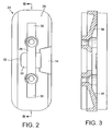
- the latch pin 20 comes into engagement with the entry ramp 34 on the latch.
- the latch pin slides up the entry ramp 34 and the latch pin is progressively moved inwardly, that is to say to the right, as seen in figure 4.
- the latch pin reaches the depression 32, its lateral movement ceases because the depth of this depression is constant.
- the biasing spring 22 urges the latch pin 20 into the latch recess.
- the gate is now latched and pivotal movement of it is prevented in both directions by engagement of the latch pin in the latch recess. In this position, vertical movement of the gate is normally prevented by engagement of the lock pin 46 with the underside of the projection 50. If, however, it is now wished to open the gate, the lock handle 42 is depressed thereby retracting the lock pin 46. The gate is then lifted and such linear movement is permitted by the sliding of the hinge pins in the hinge tube. This vertical movement results in the latch pin moving up the elongate latch recess 28 until it engages the inclined exit ramp 36.
- the gate should be slammed violently in the closing direction, it is possible that it may move so fast that the biasing spring 22 will not be able to force the latch pin into the latch recess before the latch pin has moved fully across the latch recess. In this event, the latch pin will continue moving with its end surface in sliding contact with the left-hand half, as seen in Figure 2, of the depression 30. However, the latch pin will then engage the shoulder 32 and further pivotal movement of the gate will be prevented. As a practical matter, the gate then rebounds relatively slowly in the opposite direction until the latch pin is again in registry with the latch recess and the biasing spring then urges the latch pin into the latch recess and latches the gate.
- the latch fitting 24 is disconnected from the limb 4 rotated through 180° and then reconnected.
- the entry ramp 34 now faces in the opposite direction.
- the second support fitting is disconnected from the limb 2, turned through 180° and then reconnected and this means that the other helical ramp, which is of the opposite sense, now faces upwardly.
Landscapes
- Engineering & Computer Science (AREA)
- Structural Engineering (AREA)
- Architecture (AREA)
- Civil Engineering (AREA)
- Gates (AREA)
Applications Claiming Priority (2)
| Application Number | Priority Date | Filing Date | Title |
|---|---|---|---|
| GB0420651A GB0420651D0 (en) | 2004-09-16 | 2004-09-16 | Safety gate assembly |
| EP20050254946 EP1637691A1 (de) | 2004-09-16 | 2005-08-08 | Schutzgitter für Kinder |
Related Parent Applications (1)
| Application Number | Title | Priority Date | Filing Date |
|---|---|---|---|
| EP20050254946 Division EP1637691A1 (de) | 2004-09-16 | 2005-08-08 | Schutzgitter für Kinder |
Publications (3)
| Publication Number | Publication Date |
|---|---|
| EP1798364A2 true EP1798364A2 (de) | 2007-06-20 |
| EP1798364A3 EP1798364A3 (de) | 2007-07-04 |
| EP1798364B1 EP1798364B1 (de) | 2014-07-09 |
Family
ID=33306714
Family Applications (2)
| Application Number | Title | Priority Date | Filing Date |
|---|---|---|---|
| EP20050254946 Withdrawn EP1637691A1 (de) | 2004-09-16 | 2005-08-08 | Schutzgitter für Kinder |
| EP20060077322 Expired - Lifetime EP1798364B1 (de) | 2004-09-16 | 2005-08-08 | Schutzgitter für Kinder |
Family Applications Before (1)
| Application Number | Title | Priority Date | Filing Date |
|---|---|---|---|
| EP20050254946 Withdrawn EP1637691A1 (de) | 2004-09-16 | 2005-08-08 | Schutzgitter für Kinder |
Country Status (3)
| Country | Link |
|---|---|
| US (1) | US7373755B2 (de) |
| EP (2) | EP1637691A1 (de) |
| GB (1) | GB0420651D0 (de) |
Families Citing this family (37)
| Publication number | Priority date | Publication date | Assignee | Title |
|---|---|---|---|---|
| US8448381B2 (en) | 2005-10-01 | 2013-05-28 | Carlson Pet Products, Inc. | Small gate within big gate within barrier |
| GB0701238D0 (en) * | 2007-01-23 | 2007-02-28 | Ssca Ltd | Improvements in and relating to hinges |
| GB2447655A (en) * | 2007-03-17 | 2008-09-24 | Ssca Limited | Safety gate with latch and hinge comprising skirt that conceals obliquely angled surfaces |
| GB0713455D0 (en) | 2007-07-12 | 2007-08-22 | Lindam Ltd | Gate assembley |
| US7975431B2 (en) * | 2008-05-31 | 2011-07-12 | Carlson Pet Products, Inc. | Multiple piece gated pressurized barrier |
| DE102009010682A1 (de) * | 2009-02-27 | 2010-09-02 | Indowoods Sa | Schutzgitter |
| US8713851B2 (en) | 2010-01-21 | 2014-05-06 | Mark A. Flannery | Gate having four pins and stairway post adapter |
| US20120090241A1 (en) * | 2010-03-11 | 2012-04-19 | Jean Alexander | Child proof entry system |
| US8347555B2 (en) * | 2010-07-13 | 2013-01-08 | Owen Chen | Safety fence that is closed automatically |
| US8733017B2 (en) * | 2011-10-07 | 2014-05-27 | Cosco Management, Inc. | Security gate with lock status indicator |
| CA2826550C (en) * | 2012-09-04 | 2020-10-06 | Dean Weisbeck | Gate for play yard |
| US9388603B2 (en) | 2014-03-13 | 2016-07-12 | Carlson Pet Products, Inc. | Hands free gate |
| US10081980B2 (en) * | 2014-09-05 | 2018-09-25 | Munchkin, Inc. | Mesh barrier assembly |
| US9279284B1 (en) | 2014-10-20 | 2016-03-08 | T.F.H. Publications, Inc. | Foot operated pet gate |
| CN104847251A (zh) * | 2015-05-25 | 2015-08-19 | 浙江丽童家居有限公司 | 下转轴式自动闭合安全门栏 |
| US9874055B1 (en) | 2015-08-18 | 2018-01-23 | Regalo International, Llc | Apparatus having frame separate from gate |
| US10458152B2 (en) | 2016-06-06 | 2019-10-29 | Proofed, Inc. | Gate assembly employing a dual actuator latching mechanism |
| US11523692B2 (en) | 2017-07-03 | 2022-12-13 | North States Industries, Inc. | Wall mounts for play yards |
| CN108915558B (zh) * | 2018-06-21 | 2020-01-31 | 宿州市徽腾知识产权咨询有限公司 | 一种家庭智能安防方法 |
| CN110094150B (zh) * | 2019-05-07 | 2024-08-20 | 万嘉集团有限公司 | 一种防盗门 |
| US11808084B2 (en) | 2020-01-31 | 2023-11-07 | Elbee Pty Ltd. | Gate latch |
| US11976513B2 (en) | 2020-07-09 | 2024-05-07 | North States Industries, Inc. | Security gate |
| CN215485407U (zh) * | 2021-06-15 | 2022-01-11 | 中山市依家优品日用制品有限公司 | 一种连接组件及门护栏、围栏 |
| US12352085B2 (en) | 2022-04-29 | 2025-07-08 | Elbee Pty Ltd. | Gate hinge |
| USD1021146S1 (en) | 2022-04-29 | 2024-04-02 | Elbee Pty Ltd. | Gate |
| USD1048854S1 (en) | 2022-04-29 | 2024-10-29 | Elbee Pty Ltd. | Gate latch |
| FI13298Y1 (fi) * | 2022-10-12 | 2022-11-23 | Pellon Group Oy | Saranoilla kääntyvän aitaelementin päätyprofiiliin kiinnitetty lukko |
| CN121039362A (zh) * | 2023-02-23 | 2025-11-28 | 克兹二世有限责任公司 | 易于安装的安全屏障 |
| USD1083147S1 (en) * | 2023-09-05 | 2025-07-08 | Zhongshan Yizhong Printing Co., Ltd. | Safety gate |
| USD1072278S1 (en) * | 2023-09-29 | 2025-04-22 | Zhongshan Yizhong Printing Co., Ltd. | Safety gate |
| USD1101968S1 (en) * | 2024-04-22 | 2025-11-11 | Guangzhou Fengshine Metal Products Co., Ltd | Retractable gate |
| USD1089711S1 (en) * | 2024-05-14 | 2025-08-19 | Zhongshan Ekar Uping Houseware Co., Ltd | Safety gate |
| US12258812B1 (en) * | 2024-07-19 | 2025-03-25 | Melissa Arab | High security anti-climbing pet and child confinement gate |
| USD1102624S1 (en) * | 2024-08-02 | 2025-11-18 | Guangzhou Fengshine Metal Products Co., Ltd | Safety gate |
| USD1101969S1 (en) * | 2024-08-22 | 2025-11-11 | Guangzhou Fengshine Metal Products Co., Ltd | Gate fence |
| USD1101970S1 (en) * | 2024-11-19 | 2025-11-11 | Guangzhou Fengshine Metal Products Co., Ltd | Safety gate |
| USD1112822S1 (en) * | 2024-12-16 | 2026-02-10 | Shenzhen Xinyuyou Technology Co., Ltd | Door gate |
Family Cites Families (9)
| Publication number | Priority date | Publication date | Assignee | Title |
|---|---|---|---|---|
| GB2058186B (en) * | 1979-07-24 | 1983-04-27 | Gouge G A | Safety barriers |
| TW370154U (en) * | 1998-07-08 | 1999-09-11 | shu-zhen Zheng | Modification of safety door railing |
| US6176042B1 (en) * | 1999-04-16 | 2001-01-23 | The First Years Inc. | Gate unlocking |
| GB0009253D0 (en) * | 2000-04-15 | 2000-05-31 | Beldray Ltd | A safrty gate |
| TW443423U (en) * | 2000-07-19 | 2001-06-23 | Demby Dev Co Ltd | Improved structure for security baluster door |
| GB0030540D0 (en) * | 2000-12-14 | 2001-01-31 | Hicks Robert J | Safety barrier |
| TW494965U (en) * | 2001-07-11 | 2002-07-11 | Demby Dev Co Ltd | Open-close structure for security door balustrade |
| US6637784B1 (en) * | 2001-09-27 | 2003-10-28 | Builders Hardware Inc. | One-touch-actuated multipoint latch system for doors and windows |
| DE202004014454U1 (de) * | 2004-09-16 | 2005-03-31 | Roba Baumann Gmbh | Türschutzgitter |
-
2004
- 2004-09-16 GB GB0420651A patent/GB0420651D0/en not_active Ceased
-
2005
- 2005-08-08 EP EP20050254946 patent/EP1637691A1/de not_active Withdrawn
- 2005-08-08 EP EP20060077322 patent/EP1798364B1/de not_active Expired - Lifetime
- 2005-09-13 US US11/224,044 patent/US7373755B2/en not_active Expired - Fee Related
Also Published As
| Publication number | Publication date |
|---|---|
| US7373755B2 (en) | 2008-05-20 |
| EP1637691A1 (de) | 2006-03-22 |
| EP1798364A3 (de) | 2007-07-04 |
| US20060055182A1 (en) | 2006-03-16 |
| GB0420651D0 (en) | 2004-10-20 |
| EP1798364B1 (de) | 2014-07-09 |
Similar Documents
| Publication | Publication Date | Title |
|---|---|---|
| EP1798364B1 (de) | Schutzgitter für Kinder | |
| AU2002222160B2 (en) | Safety gate assembly | |
| AU2002222160A1 (en) | Safety gate assembly | |
| US6176042B1 (en) | Gate unlocking | |
| EP2014867B1 (de) | Toranordnung, insbesondere Sicherheitsgitter für Kinder | |
| US20230349206A1 (en) | Gate latch | |
| US20060175028A1 (en) | Gate | |
| US12352085B2 (en) | Gate hinge | |
| EP2020480B1 (de) | Schutzgitter-Anordnung und Anwendungsverfahren dafür | |
| US12559983B2 (en) | Box construction lock | |
| US4408789A (en) | Safety latch for in swinging doors | |
| US20220112751A1 (en) | Poly-axial closure hinge mechanism | |
| GB2330173A (en) | Catch mechanism | |
| KR101843047B1 (ko) | 슬라이딩 잠금장치를 갖는 푸쉬풀 도어락 | |
| EP1954908B1 (de) | Kindersicherheitsbarrierenanordnungen | |
| GB2383365A (en) | Automatically closing child safety gate | |
| CN120981633A (zh) | 具有易开门的安全护栏 | |
| AU2009100296A4 (en) | Accessible Childproof Latch | |
| US941689A (en) | Latch-bolt for doors. | |
| AU2019201305B2 (en) | Lock assembly | |
| JPH0436385Y2 (de) | ||
| GB2190136A (en) | Retractable door or window stop | |
| JP4629905B2 (ja) | 開きサッシにおける施錠杆の突出防止装置及びそれを備えた開きサッシ | |
| JPH0819802B2 (ja) | 窓障子の制御装置 | |
| WO2018138721A1 (en) | A restricting device and a locking system including the restricting device |
Legal Events
| Date | Code | Title | Description |
|---|---|---|---|
| PUAI | Public reference made under article 153(3) epc to a published international application that has entered the european phase |
Free format text: ORIGINAL CODE: 0009012 |
|
| PUAL | Search report despatched |
Free format text: ORIGINAL CODE: 0009013 |
|
| 17P | Request for examination filed |
Effective date: 20070122 |
|
| AC | Divisional application: reference to earlier application |
Ref document number: 1637691 Country of ref document: EP Kind code of ref document: P |
|
| AK | Designated contracting states |
Kind code of ref document: A2 Designated state(s): AT BE BG CH CY CZ DE DK EE ES FI FR GB GR HU IE IS IT LI LT LU LV MC NL PL PT RO SE SI SK TR |
|
| AK | Designated contracting states |
Kind code of ref document: A3 Designated state(s): AT BE BG CH CY CZ DE DK EE ES FI FR GB GR HU IE IS IT LI LT LU LV MC NL PL PT RO SE SI SK TR |
|
| AKX | Designation fees paid |
Designated state(s): AT BE BG CH CY CZ DE DK EE ES FI FR GB GR HU IE IS IT LI LT LU LV MC NL PL PT RO SE SI SK TR |
|
| REG | Reference to a national code |
Ref country code: DE Ref legal event code: R079 Ref document number: 602005044167 Country of ref document: DE Free format text: PREVIOUS MAIN CLASS: E06B0009040000 Ipc: E06B0009000000 |
|
| GRAP | Despatch of communication of intention to grant a patent |
Free format text: ORIGINAL CODE: EPIDOSNIGR1 |
|
| RIC1 | Information provided on ipc code assigned before grant |
Ipc: E05F 1/06 20060101ALI20140127BHEP Ipc: E06B 9/04 20060101ALI20140127BHEP Ipc: E06B 9/00 20060101AFI20140127BHEP |
|
| INTG | Intention to grant announced |
Effective date: 20140210 |
|
| GRAS | Grant fee paid |
Free format text: ORIGINAL CODE: EPIDOSNIGR3 |
|
| GRAA | (expected) grant |
Free format text: ORIGINAL CODE: 0009210 |
|
| AC | Divisional application: reference to earlier application |
Ref document number: 1637691 Country of ref document: EP Kind code of ref document: P |
|
| AK | Designated contracting states |
Kind code of ref document: B1 Designated state(s): AT BE BG CH CY CZ DE DK EE ES FI FR GB GR HU IE IS IT LI LT LU LV MC NL PL PT RO SE SI SK TR |
|
| REG | Reference to a national code |
Ref country code: GB Ref legal event code: FG4D |
|
| REG | Reference to a national code |
Ref country code: AT Ref legal event code: REF Ref document number: 676659 Country of ref document: AT Kind code of ref document: T Effective date: 20140715 Ref country code: CH Ref legal event code: EP |
|
| REG | Reference to a national code |
Ref country code: IE Ref legal event code: FG4D |
|
| REG | Reference to a national code |
Ref country code: DE Ref legal event code: R096 Ref document number: 602005044167 Country of ref document: DE Effective date: 20140821 |
|
| REG | Reference to a national code |
Ref country code: AT Ref legal event code: MK05 Ref document number: 676659 Country of ref document: AT Kind code of ref document: T Effective date: 20140709 |
|
| REG | Reference to a national code |
Ref country code: NL Ref legal event code: VDEP Effective date: 20140709 |
|
| REG | Reference to a national code |
Ref country code: LT Ref legal event code: MG4D |
|
| PG25 | Lapsed in a contracting state [announced via postgrant information from national office to epo] |
Ref country code: SE Free format text: LAPSE BECAUSE OF FAILURE TO SUBMIT A TRANSLATION OF THE DESCRIPTION OR TO PAY THE FEE WITHIN THE PRESCRIBED TIME-LIMIT Effective date: 20140709 Ref country code: ES Free format text: LAPSE BECAUSE OF FAILURE TO SUBMIT A TRANSLATION OF THE DESCRIPTION OR TO PAY THE FEE WITHIN THE PRESCRIBED TIME-LIMIT Effective date: 20140709 Ref country code: GR Free format text: LAPSE BECAUSE OF FAILURE TO SUBMIT A TRANSLATION OF THE DESCRIPTION OR TO PAY THE FEE WITHIN THE PRESCRIBED TIME-LIMIT Effective date: 20141010 Ref country code: LT Free format text: LAPSE BECAUSE OF FAILURE TO SUBMIT A TRANSLATION OF THE DESCRIPTION OR TO PAY THE FEE WITHIN THE PRESCRIBED TIME-LIMIT Effective date: 20140709 Ref country code: FI Free format text: LAPSE BECAUSE OF FAILURE TO SUBMIT A TRANSLATION OF THE DESCRIPTION OR TO PAY THE FEE WITHIN THE PRESCRIBED TIME-LIMIT Effective date: 20140709 Ref country code: BG Free format text: LAPSE BECAUSE OF FAILURE TO SUBMIT A TRANSLATION OF THE DESCRIPTION OR TO PAY THE FEE WITHIN THE PRESCRIBED TIME-LIMIT Effective date: 20141009 Ref country code: PT Free format text: LAPSE BECAUSE OF FAILURE TO SUBMIT A TRANSLATION OF THE DESCRIPTION OR TO PAY THE FEE WITHIN THE PRESCRIBED TIME-LIMIT Effective date: 20141110 |
|
| PG25 | Lapsed in a contracting state [announced via postgrant information from national office to epo] |
Ref country code: PL Free format text: LAPSE BECAUSE OF FAILURE TO SUBMIT A TRANSLATION OF THE DESCRIPTION OR TO PAY THE FEE WITHIN THE PRESCRIBED TIME-LIMIT Effective date: 20140709 Ref country code: LV Free format text: LAPSE BECAUSE OF FAILURE TO SUBMIT A TRANSLATION OF THE DESCRIPTION OR TO PAY THE FEE WITHIN THE PRESCRIBED TIME-LIMIT Effective date: 20140709 Ref country code: AT Free format text: LAPSE BECAUSE OF FAILURE TO SUBMIT A TRANSLATION OF THE DESCRIPTION OR TO PAY THE FEE WITHIN THE PRESCRIBED TIME-LIMIT Effective date: 20140709 Ref country code: CY Free format text: LAPSE BECAUSE OF FAILURE TO SUBMIT A TRANSLATION OF THE DESCRIPTION OR TO PAY THE FEE WITHIN THE PRESCRIBED TIME-LIMIT Effective date: 20140709 Ref country code: IS Free format text: LAPSE BECAUSE OF FAILURE TO SUBMIT A TRANSLATION OF THE DESCRIPTION OR TO PAY THE FEE WITHIN THE PRESCRIBED TIME-LIMIT Effective date: 20141109 Ref country code: NL Free format text: LAPSE BECAUSE OF FAILURE TO SUBMIT A TRANSLATION OF THE DESCRIPTION OR TO PAY THE FEE WITHIN THE PRESCRIBED TIME-LIMIT Effective date: 20140709 |
|
| REG | Reference to a national code |
Ref country code: DE Ref legal event code: R119 Ref document number: 602005044167 Country of ref document: DE |
|
| REG | Reference to a national code |
Ref country code: CH Ref legal event code: PL |
|
| PG25 | Lapsed in a contracting state [announced via postgrant information from national office to epo] |
Ref country code: SK Free format text: LAPSE BECAUSE OF FAILURE TO SUBMIT A TRANSLATION OF THE DESCRIPTION OR TO PAY THE FEE WITHIN THE PRESCRIBED TIME-LIMIT Effective date: 20140709 Ref country code: CH Free format text: LAPSE BECAUSE OF NON-PAYMENT OF DUE FEES Effective date: 20140831 Ref country code: IT Free format text: LAPSE BECAUSE OF FAILURE TO SUBMIT A TRANSLATION OF THE DESCRIPTION OR TO PAY THE FEE WITHIN THE PRESCRIBED TIME-LIMIT Effective date: 20140709 Ref country code: MC Free format text: LAPSE BECAUSE OF FAILURE TO SUBMIT A TRANSLATION OF THE DESCRIPTION OR TO PAY THE FEE WITHIN THE PRESCRIBED TIME-LIMIT Effective date: 20140709 Ref country code: CZ Free format text: LAPSE BECAUSE OF FAILURE TO SUBMIT A TRANSLATION OF THE DESCRIPTION OR TO PAY THE FEE WITHIN THE PRESCRIBED TIME-LIMIT Effective date: 20140709 Ref country code: RO Free format text: LAPSE BECAUSE OF FAILURE TO SUBMIT A TRANSLATION OF THE DESCRIPTION OR TO PAY THE FEE WITHIN THE PRESCRIBED TIME-LIMIT Effective date: 20140709 Ref country code: LI Free format text: LAPSE BECAUSE OF NON-PAYMENT OF DUE FEES Effective date: 20140831 Ref country code: EE Free format text: LAPSE BECAUSE OF FAILURE TO SUBMIT A TRANSLATION OF THE DESCRIPTION OR TO PAY THE FEE WITHIN THE PRESCRIBED TIME-LIMIT Effective date: 20140709 Ref country code: DK Free format text: LAPSE BECAUSE OF FAILURE TO SUBMIT A TRANSLATION OF THE DESCRIPTION OR TO PAY THE FEE WITHIN THE PRESCRIBED TIME-LIMIT Effective date: 20140709 Ref country code: BE Free format text: LAPSE BECAUSE OF NON-PAYMENT OF DUE FEES Effective date: 20140831 |
|
| PLBE | No opposition filed within time limit |
Free format text: ORIGINAL CODE: 0009261 |
|
| STAA | Information on the status of an ep patent application or granted ep patent |
Free format text: STATUS: NO OPPOSITION FILED WITHIN TIME LIMIT |
|
| REG | Reference to a national code |
Ref country code: IE Ref legal event code: MM4A |
|
| REG | Reference to a national code |
Ref country code: FR Ref legal event code: ST Effective date: 20150430 |
|
| REG | Reference to a national code |
Ref country code: DE Ref legal event code: R119 Ref document number: 602005044167 Country of ref document: DE Effective date: 20150303 |
|
| 26N | No opposition filed |
Effective date: 20150410 |
|
| GBPC | Gb: european patent ceased through non-payment of renewal fee |
Effective date: 20141009 |
|
| PG25 | Lapsed in a contracting state [announced via postgrant information from national office to epo] |
Ref country code: GB Free format text: LAPSE BECAUSE OF NON-PAYMENT OF DUE FEES Effective date: 20141009 Ref country code: DE Free format text: LAPSE BECAUSE OF NON-PAYMENT OF DUE FEES Effective date: 20150303 |
|
| PG25 | Lapsed in a contracting state [announced via postgrant information from national office to epo] |
Ref country code: FR Free format text: LAPSE BECAUSE OF NON-PAYMENT OF DUE FEES Effective date: 20140909 Ref country code: IE Free format text: LAPSE BECAUSE OF NON-PAYMENT OF DUE FEES Effective date: 20140808 |
|
| PG25 | Lapsed in a contracting state [announced via postgrant information from national office to epo] |
Ref country code: SI Free format text: LAPSE BECAUSE OF FAILURE TO SUBMIT A TRANSLATION OF THE DESCRIPTION OR TO PAY THE FEE WITHIN THE PRESCRIBED TIME-LIMIT Effective date: 20140709 |
|
| PG25 | Lapsed in a contracting state [announced via postgrant information from national office to epo] |
Ref country code: LU Free format text: LAPSE BECAUSE OF NON-PAYMENT OF DUE FEES Effective date: 20140808 Ref country code: BE Free format text: LAPSE BECAUSE OF FAILURE TO SUBMIT A TRANSLATION OF THE DESCRIPTION OR TO PAY THE FEE WITHIN THE PRESCRIBED TIME-LIMIT Effective date: 20140709 Ref country code: HU Free format text: LAPSE BECAUSE OF FAILURE TO SUBMIT A TRANSLATION OF THE DESCRIPTION OR TO PAY THE FEE WITHIN THE PRESCRIBED TIME-LIMIT; INVALID AB INITIO Effective date: 20050808 Ref country code: TR Free format text: LAPSE BECAUSE OF FAILURE TO SUBMIT A TRANSLATION OF THE DESCRIPTION OR TO PAY THE FEE WITHIN THE PRESCRIBED TIME-LIMIT Effective date: 20140709 |