EP1798377A2 - Aube avec profilés de charge différents le long de l'envergure - Google Patents
Aube avec profilés de charge différents le long de l'envergure Download PDFInfo
- Publication number
- EP1798377A2 EP1798377A2 EP20060256347 EP06256347A EP1798377A2 EP 1798377 A2 EP1798377 A2 EP 1798377A2 EP 20060256347 EP20060256347 EP 20060256347 EP 06256347 A EP06256347 A EP 06256347A EP 1798377 A2 EP1798377 A2 EP 1798377A2
- Authority
- EP
- European Patent Office
- Prior art keywords
- loading
- convention
- airfoil
- section
- mixed
- Prior art date
- Legal status (The legal status is an assumption and is not a legal conclusion. Google has not performed a legal analysis and makes no representation as to the accuracy of the status listed.)
- Granted
Links
Images


Classifications
-
- F—MECHANICAL ENGINEERING; LIGHTING; HEATING; WEAPONS; BLASTING
- F01—MACHINES OR ENGINES IN GENERAL; ENGINE PLANTS IN GENERAL; STEAM ENGINES
- F01D—NON-POSITIVE DISPLACEMENT MACHINES OR ENGINES, e.g. STEAM TURBINES
- F01D5/00—Blades; Blade-carrying members; Heating, heat-insulating, cooling or antivibration means on the blades or the members
- F01D5/12—Blades
- F01D5/14—Form or construction
- F01D5/141—Shape, i.e. outer, aerodynamic form
-
- F—MECHANICAL ENGINEERING; LIGHTING; HEATING; WEAPONS; BLASTING
- F05—INDEXING SCHEMES RELATING TO ENGINES OR PUMPS IN VARIOUS SUBCLASSES OF CLASSES F01-F04
- F05D—INDEXING SCHEME FOR ASPECTS RELATING TO NON-POSITIVE-DISPLACEMENT MACHINES OR ENGINES, GAS-TURBINES OR JET-PROPULSION PLANTS
- F05D2250/00—Geometry
- F05D2250/70—Shape
- F05D2250/71—Shape curved
-
- Y—GENERAL TAGGING OF NEW TECHNOLOGICAL DEVELOPMENTS; GENERAL TAGGING OF CROSS-SECTIONAL TECHNOLOGIES SPANNING OVER SEVERAL SECTIONS OF THE IPC; TECHNICAL SUBJECTS COVERED BY FORMER USPC CROSS-REFERENCE ART COLLECTIONS [XRACs] AND DIGESTS
- Y02—TECHNOLOGIES OR APPLICATIONS FOR MITIGATION OR ADAPTATION AGAINST CLIMATE CHANGE
- Y02T—CLIMATE CHANGE MITIGATION TECHNOLOGIES RELATED TO TRANSPORTATION
- Y02T50/00—Aeronautics or air transport
- Y02T50/60—Efficient propulsion technologies, e.g. for aircraft
-
- Y—GENERAL TAGGING OF NEW TECHNOLOGICAL DEVELOPMENTS; GENERAL TAGGING OF CROSS-SECTIONAL TECHNOLOGIES SPANNING OVER SEVERAL SECTIONS OF THE IPC; TECHNICAL SUBJECTS COVERED BY FORMER USPC CROSS-REFERENCE ART COLLECTIONS [XRACs] AND DIGESTS
- Y10—TECHNICAL SUBJECTS COVERED BY FORMER USPC
- Y10S—TECHNICAL SUBJECTS COVERED BY FORMER USPC CROSS-REFERENCE ART COLLECTIONS [XRACs] AND DIGESTS
- Y10S416/00—Fluid reaction surfaces, i.e. impellers
- Y10S416/02—Formulas of curves
Definitions
- the present invention relates generally to airfoils and, more specifically, to a high-lift airfoil design embodying mixed loading conventions.
- Turbomachinery applications generally employ one or more components containing rotating and/or non-rotating airfoils, for example, a compressor or a turbine.
- engineers When testing the airfoils of such turbomachinery, engineers typically measure a loss of total pressure to gauge the airfoil's performance.
- Three well-known factors that engender total pressure loss in rows of turbomachinery airfoils are the behavior of the boundary layer along the airfoil surface, the behavior of the boundary layers along the inner and outer diameter end walls to which the airfoil is attached, and the interaction of the airfoil and endwall boundary layers with each other.
- Current industry practice recognizes the significance and impact of loss control but does not yet fully understand the underlying physics governing the generation of these losses.
- a fundamental mechanism of the airfoil is to turn the fluid medium in which it is present. By doing so, the airfoil will develop a distribution of fluid pressure, or a pressure loading, over its surfaces. This distribution is highly dependent on the motion of the fluid near the airfoil surface as determined by the local airfoil geometry. Thus, it is possible to influence the pressure loading of the airfoil by means of airfoil design. Designs that favor placing the bulk of the pressure loading closer to the leading edge of the airfoil are commonly referred to as front-loaded airfoils. Similarly, designs that favor placing the bulk of the pressure loading closer to the trailing edge of the airfoil are commonly referred to as aft-loaded airfoils. The distribution of loading on an airfoil surface is commonly referred to as the loading convention of the airfoil, and members of the turbomachinery industry tend to favor one loading convention over another based on their own experiences and design philosophy.
- most turbomachinery applications employ turbines and/or compressors equipped with airfoils possessing a loading convention distributed uniformly across the span of the airfoil, from root to tip, a practice which is standard within the industry.
- the airfoils may be positioned relative to one another in order to meet design requirements by varying the working medium fluid area of the passageway, that is, the minimum (or throat) area between two airfoils as measured by the integration along the airfoil span of a minimum distance line from the suction-side of one airfoil to the pressure side of an adjacent airfoil.
- the airfoils alone will ultimately not improve performance and reduce pressure losses due to the continued use of airfoils embodying standard loading conventions, that is, aft-loaded or front-loaded.
- the spanwise distribution of the total pressure loss can be categorized into two distinct regions, each controlled by a separate mechanism.
- the airfoil profile loss is highly dependent on the behavior of the airfoil surface boundary layer. It has been shown that front-loaded airfoils tend to generate less profile loss than does an aft-loaded airfoil.
- the secondary loss is highly dependent on both the end wall boundary layer as well as the interaction of the end wall boundary layer with the airfoil surface boundary layer. It has been shown that aft-loaded airfoils tend to generate less secondary loss than do front-loaded airfoils.
- the amount of loading generated by an airfoil is of interest.
- the load value of an airfoil may be expressed as a non-dimensional loading parameter known as the Zweifel load coefficient as known to one of ordinary skill in the art.
- the Zweifel load coefficient is a ratio of the actual airfoil load to the ideal airfoil load.
- the loading per airfoil can be controlled by adjusting either or both the airfoil count or the airfoil size. For example, a reduction in either of these two parameters can reduce both weight and cost of the airfoil while in turn increasing the airfoil loading.
- increased airfoil loading may push the airfoil into an unfavorable operational regime with respect to increased airfoil secondary flow losses.
- high-lift airfoils generally possess a Zweifel load coefficient of greater than 1.2.
- the use of high-lift airfoils for turbomachinery applications is typically avoided due to certain performance obstacles. It has been observed that turbomachinery utilizing high-lift airfoils may exhibit airfoil flow separation or undesirable boundary layer thickening as well as greater secondary losses.
- One conventional airfoil design of the prior art achieved a Zweifel load coefficient of up to 1.16 by employing an airfoil having a mixed-loading convention.
- a Zweifel load coefficient greater than 1.16 the size of each airfoil had to be adjusted and/or the number of airfoils had to be changed.
- a blade broadly comprises a platform; a concave pressure side; a convex suction side; and an airfoil broadly comprising a root section comprising a first loading convention and an attachment engaged to the platform; a midspan section comprising a second loading convention; a tip section comprising a third loading convention, wherein a spanwise distribution of the first loading convention, the second loading convention and the third loading convention across a span of the airfoil comprises a mixed-loading convention and a Zweifel load coefficient equal to about or greater than about 1.2.
- a vane broadly comprises a platform; a concave pressure side; a convex suction side; and an airfoil broadly comprising a root section comprising a first loading convention, wherein the root section further comprises an attachment engaging the platform; a midspan section comprising a second loading convention; a tip section comprising a third loading convention; and wherein a spanwise distribution of the first loading convention, the second loading convention and the third loading convention across a span of said airfoil comprises a mixed-loading convention and a Zweifel load coefficient equal to about or greater than about 1.2.
- a method of turning air in a turbomachinery application broadly comprises applying a working medium fluid comprising at least one direction and a velocity to a turbine of the turbomachinery application, wherein the at least one direction of the fluid is parallel to a centerline of the turbine and the turbine comprises a plurality of mixed-loading airfoils positioned to reduce pressure losses experienced by the turbine; and turning the fluid as the fluid passes through the plurality of mixed-loading airfoils of the turbine; wherein the airfoils comprise a root section comprising a first loading convention, a midspan section comprising a second loading convention, a tip section comprising a third loading convention, wherein a spanwise distribution of the first loading convention, the second loading convention and the third loading convention across a span of the airfoil comprises a mixed-loading convention and a Zweifel load coefficient equal to about or greater than about 1.2.
- An airfoil embodying a combination of loading conventions in a single high-lift design specifically to reduce and control the total pressure losses that occur in the working medium fluid passages between airfoils employed in turbomachinery applications is disclosed herein.
- a high-lift airfoil embodying mixed-loading conventions exhibits the most favorable total pressure loss characteristics possessed by both aft-loaded airfoil and front-loaded airfoil conventions.
- such mixed-loading conventions are capable of more favorably influencing the development of an airfoil surface boundary layer in such applications, as well as the interaction of airfoil surface boundary layers with the endwall boundary layers.
- the high-lift airfoil design(s) of the present invention overcome these performance obstacles using a mixed-loading convention described herein.
- the high-lift airfoil design(s) embodying a mixed-loading convention of the present invention will exhibit a Zweifel load coefficient equal to about or greater than about 1.2 yet will not in turn produce airfoil flow separation or increased secondary losses unlike prior art airfoil designs.
- airfoil designs will always possess two distinct surfaces, that is, a pressure side and a suction side, which results in the turning of the working medium fluid during the airfoil's use. Alterations may be made to the airfoil's design in order to increase and/or decrease the turning of the working medium fluid pursuant to the desired application as is known to one of ordinary skill in the art.
- a mixed-loading airfoil design described herein combines aft-loading conventions and front-loading conventions while also employing airfoil surfaces possessing different distributions of curvature along its span.
- the airfoil's ability to influence the behavior of the boundary layers forming along its surfaces, as well as influencing the interaction of airfoil surface boundary layers and endwall boundary layers, and possessing the benefits of both aft-loaded and front-loaded designs are a function of these curvature values.
- the thickness of the mixed-loaded airfoils may be varied accordingly for the intended applications as known to one of ordinary skill in the art; however, changes in airfoil thickness will result in changes to the curvature of the airfoil surface.
- the present mixed airfoil design may be utilized beyond the turbomachinery applications initially considered.
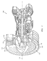
- the gas turbine engine 100 may comprise a rotating turbine blade assembly 120 comprising a plurality of blades 140 comprising mixed-loading airfoils and a stationary turbine vane assembly comprising a plurality of vanes 150 comprising mixed-loading airfoils.
- Each airfoil has a root section, a midspan section, and a tip section, and a leading edge located at or near the upstream end of the airfoil and a trailing edge located at or near the downstream end of the airfoil.
- the root section and/or tip section of each vane will be attached to both the inner- and outer-diameter endwalls.
- each blade will be attached to a platform and configured to fixedly engage the disk of the engine.
- the blade may be shrouded, meaning the blade tip section is attached to a portion of the outer endwall that is rotating at the same rate as the blade itself.
- the blade may also be unshrouded, meaning the blade tip section is not attached to the outer endwall. In this configuration, the outer endwall is not rotating, and a gap exists between the blade tip section and the endwall.
- a mixed-loading airfoil may comprise a root section 12, a midspan section 14, a tip section 16.
- a concave surface 18 along the span of the airfoil from root section 12 to tip 16 is referred to as a pressure side 20, while the convex surface 22 along the span of the airfoil from root section 12 to tip section 16 is referred to as a suction-side 24.
- FIG. 2b illustrates a cross-sectional view of tip section 16 of airfoil 10
- FIG. 2c illustrates a cross-sectional view of midspan section 14 of airfoil 10
- FIG. 2b illustrates a cross-sectional view of tip section 16 of airfoil 10
- FIG. 2c illustrates a cross-sectional view of midspan section 14 of airfoil 10
- FIGS. 2b-2d illustrates a cross-sectional view of root section 12 of airfoil 10.
- An axial chord 26 is depicted in each of FIGS. 2b-2d.
- Axial chord is defined as the axial length of the projection of the airfoil onto a plane containing the engine axis. It should be noted that axial chord 26 is not required to maintain a constant length along the span of the airfoil, for the root section, midspan section, and tip section of airfoil 10.
- FIGS. 3a-4b depict a cross-section of a typical aft-loaded root section 12 or tip section 16 of airfoil 10 and an aft-loaded section's representative pressure distribution graph, respectively.
- the suction-side curvature graphs shown in each figure represent the curvature values calculated using a derivative of the measurements taken at points along the surface of suction-side 24 of each section respectively as known to one of ordinary skill in the art.
- the airfoil section is oriented in an engine-installed frame of reference, with the X axis parallel to the centerline axis of the engine and the Y axis extending in the pitchwise, or rotational, axis of the engine.
- the positive direction of the X axis unit vector is from the front of the engine towards the back of the engine.
- the positive direction of the Y axis unit vector is from the airfoil pressure side to the airfoil suction side.
- the coordinate system of FIGS. 3a and 3b utilize the previously mentioned X and Y axes, with the X-axis origin being located at the airfoil leading edge point and the X and Y coordinates being normalized to the airfoil axial chord length.
- the suction-side curvature graph of aft-loaded root and tip sections 12, 16 of airfoil 10 indicates that the maximum curvature of suction-side 24 may occur near or approximate to a midpoint of axial chord 26.
- suction-side curvature graph of front-loaded midspan section 14 of airfoil 10 indicates the maximum curvature of suction-side 24 may occur near or approximate to a quarterpoint of axial chord 26.
- the location of the maximum curvature of the front-loaded midspan section will always be upstream of the locations for the maximum curvature for both the aft-loaded root and tip sections 12, 16.
- the location of the maximum curvature may vary depending upon the velocity being applied to the blade or vane by the working medium fluid produced by the turbine engine.
- velocity is generally expressed in non-dimensional terms as a "Mach number", calculated as the ratio of the speed of an object to the speed of sound in the surrounding medium.
- the object of relevance is the working medium fluid.
- a general operating velocity of a working medium fluid for turbomachinery applications may comprise a range of about Mach 0.1 to about Mach 2.0.
- a moderate Mach operating range may comprise about Mach 0.1 to about Mach 1.0, while a high Mach operating range may comprise about Mach 1.0 to about Mach 2.0.
- the operating range of the working medium fluid may vary from about Mach 0.5 to about Mach 1.5.
- the bulk of the pressure loading for the front-loaded midspan section will still be located upstream with respect to the bulk of the pressure loading for both the aft-loaded root and tip sections.
- the increase in the Mach number causes the working medium fluid to flow along the surface of the airfoil differently, thus affecting the airfoil surface boundary layer and potentially increasing the airfoil's profile loss.
- repositioning airfoils relative to each other will not ultimately improve performance and reduce the airfoil's profile loss.
- the resulting design of the mixed-loading airfoil described herein becomes dependent upon the intended turbomachinery application's Mach number and may change from application to application.
- a blade or vane may be measured using one or more methods known to one of ordinary skill in the art to determine whether the airfoil of a blade or vane embodies a mixed-loading convention. It is contemplated that the mixed-loading airfoils described herein may be utilized in various turbomachinery applications and for applications outside turbomachinery where the velocity of the working medium fluid is less than about Mach 0.1 and greater than about Mach 2.0.
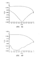
- sample pressure distribution graphs shown in FIGS. 4a and 4b represent pressure distribution across aft-loaded airfoils and front-loaded airfoils alone.
- sample pressure distribution graphs of FIGS. 4a and 4b may be read and interpreted in light of a spanwise total pressure loss distribution plot shown in FIG. 5.
- the sample pressure distribution graph charts the normalized static pressure [P/P 0 ] versus the normalized axial chord [X/B x ] for a conventional aft-loaded airfoil design.
- the upper line on each graph shows the normalized pressure of a working medium fluid flowing over the pressure side, or a higher-pressure surface, of an aft-loaded airfoil design while the lower line on each graph shows the normalized pressure of a working medium fluid flowing along the suction-side, or a lower pressure surface, of the aft-loaded airfoil design.
- a negative slope value represents the acceleration of the working medium fluid across the surface of the aft-loaded airfoil while a positive slope indicates deceleration of the working medium fluid along the surface of the aft-loaded airfoil.
- the value of the slope of the pressure distribution is indicative of the strength of the fluid acceleration or fluid deceleration.
- the sample pressure distribution graph of FIG. 4a indicates that as the working medium fluid flows along the suction-side of the aft-loaded airfoil, the fluid initially accelerates within a converging flow channel until reaching an approximate mid-chord region corresponding to the flow passage throat location. As the fluid passes this location, the flow channel widens and the fluid begins to decelerate as it approaches the airfoil trailing edge. The fluid deceleration will cause the airfoil surface boundary layer to thicken rather quickly within this region of strong adverse pressure gradient, which will contribute to the airfoil's profile loss. In contrast to how the working medium fluid flows along the suction-side surface, the fluid flowing along the pressure side surface of the aft-loaded airfoil gradually accelerates within the constricting flow channel.
- the airflow gradually accelerates from the leading edge to the trailing edge.
- the fluid velocity initially increases very quickly around the leading edge and then decelerates until approximately 0.05 along the normalized axial chord scale [x/B x ] of FIG. 4b.
- the fluid velocity accelerates to approximately 0.30 normalized axial location and then gradually decelerates until reaching a value of approximately 0.98 along the normalized static pressure scale [P/P 0 ] of FIG. 4b.
- the deceleration of the fluid causes a total pressure loss to occur due to a thickening of the airfoil boundary layer within the unfavorable pressure gradient, though the strength of the deceleration is less than that of the aft-loaded design.
- FIG. 5 the spanwise distribution of total pressure loss for an aft-loaded airfoil of the prior art, a front-loaded airfoil of the prior art, and an embodiment of the mixed-loaded airfoil described herein are shown over half the span of the airfoil.
- the front-loaded design has lower profile losses in the midspan region than the aft-loaded airfoil.
- the aft-loaded airfoil has lower secondary losses than the front-loaded design close to the endwalls.
- the mixed-loading airfoil described herein combines the positive characteristics of both the aft-loaded and front-loaded airfoil spanwise total pressure loss distributions as illustrated in FIG. 5.
- the mixed-loading airfoil possesses an airfoil profile loss lower than that of the aft-loaded airfoil and similar to that of the front-loaded airfoil.
- the mixed-loading airfoil possesses secondary losses lower than those of the front-loaded airfoil and similar to that of the aft-loaded airfoil.
- the mixed-loaded design combines into one design the best profile and secondary loss features of both the front- and aft-loaded airfoil geometries.
- the mixed-loading airfoil designs described herein may be utilized in blades and/or vanes to reduce pressure losses experienced by, for example, gas turbine engines incorporating both rotating and stationary turbomachinery components.
- a gas turbine engine 100 may comprise a rotating turbine blade assembly 120 comprising a plurality of blades 140 embodying the mixed-loading airfoil design and positioned to reduce pressure losses experienced by the turbine engine.
- a working medium fluid having a direction and a velocity flows parallel to a centerline 110 through gas turbine engine 100.
- the mixed-loading airfoil design minimizes the development and interaction of boundary layers forming along the airfoil and endwall surfaces.
- a gas turbine engine 100 may comprise a stationary turbine vane assembly 130 comprising a plurality of vanes 150 embodying the mixed-loading airfoil design and positioned to reduce pressure losses experienced by the turbine engine.
- a working medium fluid having a direction and a velocity flows parallel to centerline 110 through the gas turbine engine 100.
- the mixed airfoil design minimizes the development and interaction of boundary layers forming along the airfoil and endwall surfaces.
Landscapes
- Engineering & Computer Science (AREA)
- Physics & Mathematics (AREA)
- Fluid Mechanics (AREA)
- Mechanical Engineering (AREA)
- General Engineering & Computer Science (AREA)
- Turbine Rotor Nozzle Sealing (AREA)
- Structures Of Non-Positive Displacement Pumps (AREA)
Applications Claiming Priority (1)
| Application Number | Priority Date | Filing Date | Title |
|---|---|---|---|
| US11/303,672 US7686567B2 (en) | 2005-12-16 | 2005-12-16 | Airfoil embodying mixed loading conventions |
Publications (3)
| Publication Number | Publication Date |
|---|---|
| EP1798377A2 true EP1798377A2 (fr) | 2007-06-20 |
| EP1798377A3 EP1798377A3 (fr) | 2011-03-16 |
| EP1798377B1 EP1798377B1 (fr) | 2015-10-14 |
Family
ID=37726626
Family Applications (1)
| Application Number | Title | Priority Date | Filing Date |
|---|---|---|---|
| EP06256347.3A Active EP1798377B1 (fr) | 2005-12-16 | 2006-12-13 | Aube avec profilés de charge différents le long de l'envergure |
Country Status (4)
| Country | Link |
|---|---|
| US (1) | US7686567B2 (fr) |
| EP (1) | EP1798377B1 (fr) |
| JP (1) | JP2007224898A (fr) |
| CN (1) | CN1982653A (fr) |
Cited By (3)
| Publication number | Priority date | Publication date | Assignee | Title |
|---|---|---|---|---|
| FR2977908A1 (fr) * | 2011-07-13 | 2013-01-18 | Snecma | Aube de turbomachine |
| EP3168417A1 (fr) * | 2015-11-16 | 2017-05-17 | General Electric Company | Conceptions de sustentation optimale pour turbine à gaz |
| US10208765B2 (en) | 2015-01-28 | 2019-02-19 | MTU Aero Engines AG | Gas turbine axial compressor |
Families Citing this family (49)
| Publication number | Priority date | Publication date | Assignee | Title |
|---|---|---|---|---|
| JP2009511811A (ja) * | 2005-10-11 | 2009-03-19 | アルストム テクノロジー リミテッド | ターボ機械用翼 |
| US8157518B2 (en) * | 2007-03-05 | 2012-04-17 | Xcelaero Corporation | Low camber microfan |
| WO2008109036A1 (fr) * | 2007-03-05 | 2008-09-12 | Xcelaero Corporation | Ventilateur de refroidissement à rendement élevé |
| JP2009197650A (ja) * | 2008-02-20 | 2009-09-03 | Mitsubishi Heavy Ind Ltd | ガスタービン |
| DE102008031781B4 (de) * | 2008-07-04 | 2020-06-10 | Man Energy Solutions Se | Schaufelgitter für eine Strömungsmaschine und Strömungsmaschine mit einem solchen Schaufelgitter |
| EP2146054A1 (fr) * | 2008-07-17 | 2010-01-20 | Siemens Aktiengesellschaft | Turbine axiale pour une turbine à gaz |
| US8257045B2 (en) * | 2008-08-15 | 2012-09-04 | United Technologies Corp. | Platforms with curved side edges and gas turbine engine systems involving such platforms |
| DE102008060847B4 (de) * | 2008-12-06 | 2020-03-19 | MTU Aero Engines AG | Strömungsmaschine |
| JP5479300B2 (ja) * | 2010-10-22 | 2014-04-23 | 三菱重工業株式会社 | 風車翼およびこれを備えた風力発電装置ならびに風車翼の設計方法 |
| CN101988522B (zh) * | 2010-12-01 | 2012-08-29 | 鑫贺精密电子(东莞)有限公司 | 散热风扇 |
| EP2476862B1 (fr) * | 2011-01-13 | 2013-11-20 | Alstom Technology Ltd | Aube statorique pour turbomachine à flux axial et turbomachine associée |
| JP5603800B2 (ja) * | 2011-02-22 | 2014-10-08 | 株式会社日立製作所 | タービン静翼、およびそれを用いた蒸気タービン設備 |
| US20130156602A1 (en) † | 2011-12-16 | 2013-06-20 | United Technologies Corporation | Film cooled turbine component |
| WO2014137686A1 (fr) * | 2013-03-04 | 2014-09-12 | United Technologies Corporation | Refroidissement de turbine à gaz à profil aérodynamique haute portance dans une zone de stagnation |
| US9688395B2 (en) | 2013-12-04 | 2017-06-27 | Sikorsky Aircraft Corporation | Boundary layer ingesting blade |
| CN103670528B (zh) * | 2013-12-20 | 2015-04-22 | 东方电气集团东方汽轮机有限公司 | 透平叶片的加载方法 |
| WO2015126715A1 (fr) | 2014-02-19 | 2015-08-27 | United Technologies Corporation | Profil aérodynamique de turbine à gaz |
| US9567858B2 (en) | 2014-02-19 | 2017-02-14 | United Technologies Corporation | Gas turbine engine airfoil |
| EP3108106B1 (fr) | 2014-02-19 | 2022-05-04 | Raytheon Technologies Corporation | Pale de moteur à turbine à gaz |
| EP3108109B1 (fr) | 2014-02-19 | 2023-09-13 | Raytheon Technologies Corporation | Aube de soufflante de moteur à turbine à gaz |
| EP3108122B1 (fr) | 2014-02-19 | 2023-09-20 | Raytheon Technologies Corporation | Moteur à double flux à engrenage avec aubes de compresseur basse pression |
| EP3108101B1 (fr) | 2014-02-19 | 2022-04-20 | Raytheon Technologies Corporation | Profil aérodynamique de moteur à turbine à gaz |
| US9599064B2 (en) | 2014-02-19 | 2017-03-21 | United Technologies Corporation | Gas turbine engine airfoil |
| EP4509698A3 (fr) | 2014-02-19 | 2025-05-28 | RTX Corporation | Aube de turbine à gaz |
| US10557477B2 (en) | 2014-02-19 | 2020-02-11 | United Technologies Corporation | Gas turbine engine airfoil |
| EP3108100B1 (fr) | 2014-02-19 | 2021-04-14 | Raytheon Technologies Corporation | Pale de soufflante de moteur à turbine à gaz |
| US10495106B2 (en) | 2014-02-19 | 2019-12-03 | United Technologies Corporation | Gas turbine engine airfoil |
| WO2015127032A1 (fr) | 2014-02-19 | 2015-08-27 | United Technologies Corporation | Surface portante pour turbine à gaz |
| EP4279706A3 (fr) | 2014-02-19 | 2024-02-28 | RTX Corporation | Aube de turbine à gaz |
| EP3108113A4 (fr) | 2014-02-19 | 2017-03-15 | United Technologies Corporation | Profil aérodynamique de turbine à gaz |
| WO2015175051A2 (fr) | 2014-02-19 | 2015-11-19 | United Technologies Corporation | Profil aérodynamique de moteur à turbine à gaz |
| EP3108116B1 (fr) | 2014-02-19 | 2024-01-17 | RTX Corporation | Moteur à turbine à gaz |
| EP3108104B1 (fr) | 2014-02-19 | 2019-06-12 | United Technologies Corporation | Surface portante de moteur à turbine à gaz |
| US10590775B2 (en) | 2014-02-19 | 2020-03-17 | United Technologies Corporation | Gas turbine engine airfoil |
| WO2015175045A2 (fr) | 2014-02-19 | 2015-11-19 | United Technologies Corporation | Surface portante de moteur à turbine à gaz |
| WO2015126450A1 (fr) | 2014-02-19 | 2015-08-27 | United Technologies Corporation | Surface portante pour turbine à gaz |
| EP3575551B1 (fr) | 2014-02-19 | 2021-10-27 | Raytheon Technologies Corporation | Surface portante de moteur à turbine à gaz |
| EP3108103B1 (fr) | 2014-02-19 | 2023-09-27 | Raytheon Technologies Corporation | Aube de soufflante pour moteur à turbine à gaz |
| EP2921647A1 (fr) | 2014-03-20 | 2015-09-23 | Alstom Technology Ltd | Aube de turbine à gaz avec bord d'attaque et bord de fuite courbés |
| CN104895618B (zh) * | 2015-04-10 | 2017-02-01 | 中国科学院工程热物理研究所 | 超高负荷低压涡轮叶片、高负荷低压涡轮、航空燃气涡轮发动机 |
| US11248622B2 (en) | 2016-09-02 | 2022-02-15 | Raytheon Technologies Corporation | Repeating airfoil tip strong pressure profile |
| US11286787B2 (en) * | 2016-09-15 | 2022-03-29 | Raytheon Technologies Corporation | Gas turbine engine airfoil with showerhead cooling holes near leading edge |
| US11255070B2 (en) | 2018-06-15 | 2022-02-22 | Clark Equipment Company | Hydraulic coupling |
| JP6998462B2 (ja) | 2018-06-22 | 2022-01-18 | 三菱重工エンジン&ターボチャージャ株式会社 | 回転翼及びこの回転翼を備える遠心圧縮機 |
| CN110566285B (zh) * | 2019-08-26 | 2022-02-18 | 中国人民解放军总参谋部第六十研究所 | 一种紧凑型向心涡轮导向器 |
| CN111259559B (zh) * | 2020-02-02 | 2023-03-24 | 上海交通大学 | 悬臂静子叶片前加载设计减小损失的流动控制方法 |
| US12366167B2 (en) * | 2022-08-09 | 2025-07-22 | Rtx Corporation | Fan blade or vane with improved bird impact capability |
| EP4653684A3 (fr) * | 2022-08-09 | 2025-12-10 | RTX Corporation | Pale ou pale de ventilateur avec capacité d'impact d'oiseau améliorée |
| CN115506937A (zh) * | 2022-10-20 | 2022-12-23 | 中国船舶集团有限公司第七○八研究所 | 用于透平机械二次流抑制的叶片混合翼型构型 |
Citations (1)
| Publication number | Priority date | Publication date | Assignee | Title |
|---|---|---|---|---|
| EP1057969A2 (fr) | 1999-06-03 | 2000-12-06 | Ebara Corporation | Aubage de turbine |
Family Cites Families (5)
| Publication number | Priority date | Publication date | Assignee | Title |
|---|---|---|---|---|
| DE59907976D1 (de) * | 1998-02-20 | 2004-01-22 | Rolls Royce Deutschland | Anordnung von Axialturbinenschaufeln |
| US6312219B1 (en) * | 1999-11-05 | 2001-11-06 | General Electric Company | Narrow waist vane |
| JP4484396B2 (ja) * | 2001-05-18 | 2010-06-16 | 株式会社日立製作所 | タービン動翼 |
| WO2003027461A1 (fr) * | 2001-09-24 | 2003-04-03 | Alstom Technology Ltd | Systeme de turbine a gaz destine a un fluide de travail se presentant sous la forme d'un melange dioxyde de carbone/eau |
| JP2009511811A (ja) * | 2005-10-11 | 2009-03-19 | アルストム テクノロジー リミテッド | ターボ機械用翼 |
-
2005
- 2005-12-16 US US11/303,672 patent/US7686567B2/en active Active
-
2006
- 2006-12-12 JP JP2006333938A patent/JP2007224898A/ja active Pending
- 2006-12-13 EP EP06256347.3A patent/EP1798377B1/fr active Active
- 2006-12-15 CN CNA2006101732924A patent/CN1982653A/zh active Pending
Patent Citations (1)
| Publication number | Priority date | Publication date | Assignee | Title |
|---|---|---|---|---|
| EP1057969A2 (fr) | 1999-06-03 | 2000-12-06 | Ebara Corporation | Aubage de turbine |
Non-Patent Citations (1)
| Title |
|---|
| HOUTERMANS ET AL.: "Aerodynamic performance of a very high lift low pressure turbine blade with emphasis on separation prediction", JOURNAL OF TURBOMACHINERY, vol. 126, 1 July 2004 (2004-07-01), pages 406 - 413, XP002619187, DOI: doi:10.1115/1.1748416 |
Cited By (4)
| Publication number | Priority date | Publication date | Assignee | Title |
|---|---|---|---|---|
| FR2977908A1 (fr) * | 2011-07-13 | 2013-01-18 | Snecma | Aube de turbomachine |
| US9022744B2 (en) | 2011-07-13 | 2015-05-05 | Snecma | Turbine engine blade |
| US10208765B2 (en) | 2015-01-28 | 2019-02-19 | MTU Aero Engines AG | Gas turbine axial compressor |
| EP3168417A1 (fr) * | 2015-11-16 | 2017-05-17 | General Electric Company | Conceptions de sustentation optimale pour turbine à gaz |
Also Published As
| Publication number | Publication date |
|---|---|
| JP2007224898A (ja) | 2007-09-06 |
| US20090317227A1 (en) | 2009-12-24 |
| US7686567B2 (en) | 2010-03-30 |
| CN1982653A (zh) | 2007-06-20 |
| EP1798377A3 (fr) | 2011-03-16 |
| EP1798377B1 (fr) | 2015-10-14 |
Similar Documents
| Publication | Publication Date | Title |
|---|---|---|
| EP1798377B1 (fr) | Aube avec profilés de charge différents le long de l'envergure | |
| EP1152122B1 (fr) | Jeu d'aubes de turbomachine | |
| EP1967694B1 (fr) | Aube de turbine d'une turbomachine | |
| US9046111B2 (en) | Compressor aerofoil | |
| EP2492440B1 (fr) | Aube statorique de turbine et équipement de turbine à vapeur l'utilisant | |
| EP2333242B1 (fr) | Contrôle de vortex de l'extrémité sur une aube de rotor pour un moteur à turbine à gaz | |
| US9556740B2 (en) | Turbine engine blade, in particular for a one-piece bladed disk | |
| US7597544B2 (en) | Blade of axial flow-type rotary fluid machine | |
| EP2476862B1 (fr) | Aube statorique pour turbomachine à flux axial et turbomachine associée | |
| EP1260674B1 (fr) | Turbine et aube de turbine | |
| EP3382148B1 (fr) | Aube pour moteur à turbine à gaz avec un plateau de pointe | |
| JPH10502150A (ja) | 回転機械の圧縮領域のための流れ配向アッセンブリ | |
| US7794202B2 (en) | Turbine blade | |
| US11125085B2 (en) | Blade of fan or compressor | |
| EP3327251B1 (fr) | Aube de stator de compresseur avec bord d'attaque de balayage vers l'avant | |
| US11203945B2 (en) | Stator vane of fan or compressor | |
| EP3404212B1 (fr) | Élément de surface portante de compresseur | |
| EP3263837B1 (fr) | Élément d'aubage de compresseur axial de récupération de la pression | |
| RU2794951C2 (ru) | Лопатка газотурбинного двигателя с правилом максимальной толщины с большим запасом прочности при флаттере | |
| EP2075409A2 (fr) | Bord d'attaque de profil aérodynamique | |
| Bolger | Harvey et al. |
Legal Events
| Date | Code | Title | Description |
|---|---|---|---|
| PUAI | Public reference made under article 153(3) epc to a published international application that has entered the european phase |
Free format text: ORIGINAL CODE: 0009012 |
|
| AK | Designated contracting states |
Kind code of ref document: A2 Designated state(s): AT BE BG CH CY CZ DE DK EE ES FI FR GB GR HU IE IS IT LI LT LU LV MC NL PL PT RO SE SI SK TR |
|
| AX | Request for extension of the european patent |
Extension state: AL BA HR MK RS |
|
| PUAL | Search report despatched |
Free format text: ORIGINAL CODE: 0009013 |
|
| AK | Designated contracting states |
Kind code of ref document: A3 Designated state(s): AT BE BG CH CY CZ DE DK EE ES FI FR GB GR HU IE IS IT LI LT LU LV MC NL PL PT RO SE SI SK TR |
|
| AX | Request for extension of the european patent |
Extension state: AL BA HR MK RS |
|
| 17P | Request for examination filed |
Effective date: 20110914 |
|
| AKX | Designation fees paid |
Designated state(s): DE GB |
|
| 17Q | First examination report despatched |
Effective date: 20150116 |
|
| GRAP | Despatch of communication of intention to grant a patent |
Free format text: ORIGINAL CODE: EPIDOSNIGR1 |
|
| INTG | Intention to grant announced |
Effective date: 20150422 |
|
| GRAS | Grant fee paid |
Free format text: ORIGINAL CODE: EPIDOSNIGR3 |
|
| GRAA | (expected) grant |
Free format text: ORIGINAL CODE: 0009210 |
|
| AK | Designated contracting states |
Kind code of ref document: B1 Designated state(s): DE GB |
|
| REG | Reference to a national code |
Ref country code: GB Ref legal event code: FG4D |
|
| REG | Reference to a national code |
Ref country code: DE Ref legal event code: R081 Ref document number: 602006046917 Country of ref document: DE Owner name: UNITED TECHNOLOGIES CORP. (N.D.GES.D. STAATES , US Free format text: FORMER OWNER: UNITED TECHNOLOGIES CORP. (N.D.GES.D. STAATES DELAWARE), HARTFORD, CONN., US |
|
| REG | Reference to a national code |
Ref country code: DE Ref legal event code: R096 Ref document number: 602006046917 Country of ref document: DE |
|
| REG | Reference to a national code |
Ref country code: DE Ref legal event code: R097 Ref document number: 602006046917 Country of ref document: DE |
|
| PLBE | No opposition filed within time limit |
Free format text: ORIGINAL CODE: 0009261 |
|
| STAA | Information on the status of an ep patent application or granted ep patent |
Free format text: STATUS: NO OPPOSITION FILED WITHIN TIME LIMIT |
|
| 26N | No opposition filed |
Effective date: 20160715 |
|
| REG | Reference to a national code |
Ref country code: DE Ref legal event code: R082 Ref document number: 602006046917 Country of ref document: DE Representative=s name: SCHMITT-NILSON SCHRAUD WAIBEL WOHLFROM PATENTA, DE |
|
| REG | Reference to a national code |
Ref country code: DE Ref legal event code: R082 Ref document number: 602006046917 Country of ref document: DE Representative=s name: SCHMITT-NILSON SCHRAUD WAIBEL WOHLFROM PATENTA, DE Ref country code: DE Ref legal event code: R081 Ref document number: 602006046917 Country of ref document: DE Owner name: UNITED TECHNOLOGIES CORP. (N.D.GES.D. STAATES , US Free format text: FORMER OWNER: UNITED TECHNOLOGIES CORP., HARTFORD, CONN., US |
|
| PGFP | Annual fee paid to national office [announced via postgrant information from national office to epo] |
Ref country code: DE Payment date: 20191119 Year of fee payment: 14 |
|
| REG | Reference to a national code |
Ref country code: DE Ref legal event code: R119 Ref document number: 602006046917 Country of ref document: DE |
|
| PG25 | Lapsed in a contracting state [announced via postgrant information from national office to epo] |
Ref country code: DE Free format text: LAPSE BECAUSE OF NON-PAYMENT OF DUE FEES Effective date: 20210701 |
|
| PGFP | Annual fee paid to national office [announced via postgrant information from national office to epo] |
Ref country code: GB Payment date: 20251120 Year of fee payment: 20 |