EP1798416B1 - Rotationsverdichter mit verbesserter Leistung und dazugehöriges Verfahren - Google Patents
Rotationsverdichter mit verbesserter Leistung und dazugehöriges Verfahren Download PDFInfo
- Publication number
- EP1798416B1 EP1798416B1 EP06025093A EP06025093A EP1798416B1 EP 1798416 B1 EP1798416 B1 EP 1798416B1 EP 06025093 A EP06025093 A EP 06025093A EP 06025093 A EP06025093 A EP 06025093A EP 1798416 B1 EP1798416 B1 EP 1798416B1
- Authority
- EP
- European Patent Office
- Prior art keywords
- pressure
- oil
- compressor
- line
- low
- Prior art date
- Legal status (The legal status is an assumption and is not a legal conclusion. Google has not performed a legal analysis and makes no representation as to the accuracy of the status listed.)
- Active
Links
Images

Classifications
-
- F—MECHANICAL ENGINEERING; LIGHTING; HEATING; WEAPONS; BLASTING
- F04—POSITIVE - DISPLACEMENT MACHINES FOR LIQUIDS; PUMPS FOR LIQUIDS OR ELASTIC FLUIDS
- F04C—ROTARY-PISTON, OR OSCILLATING-PISTON, POSITIVE-DISPLACEMENT MACHINES FOR LIQUIDS; ROTARY-PISTON, OR OSCILLATING-PISTON, POSITIVE-DISPLACEMENT PUMPS
- F04C28/00—Control of, monitoring of, or safety arrangements for, pumps or pumping installations specially adapted for elastic fluids
- F04C28/06—Control of, monitoring of, or safety arrangements for, pumps or pumping installations specially adapted for elastic fluids specially adapted for stopping, starting, idling or no-load operation
-
- F—MECHANICAL ENGINEERING; LIGHTING; HEATING; WEAPONS; BLASTING
- F04—POSITIVE - DISPLACEMENT MACHINES FOR LIQUIDS; PUMPS FOR LIQUIDS OR ELASTIC FLUIDS
- F04B—POSITIVE-DISPLACEMENT MACHINES FOR LIQUIDS; PUMPS
- F04B39/00—Component parts, details, or accessories, of pumps or pumping systems specially adapted for elastic fluids, not otherwise provided for in, or of interest apart from, groups F04B25/00 - F04B37/00
- F04B39/02—Lubrication
-
- F—MECHANICAL ENGINEERING; LIGHTING; HEATING; WEAPONS; BLASTING
- F04—POSITIVE - DISPLACEMENT MACHINES FOR LIQUIDS; PUMPS FOR LIQUIDS OR ELASTIC FLUIDS
- F04C—ROTARY-PISTON, OR OSCILLATING-PISTON, POSITIVE-DISPLACEMENT MACHINES FOR LIQUIDS; ROTARY-PISTON, OR OSCILLATING-PISTON, POSITIVE-DISPLACEMENT PUMPS
- F04C29/00—Component parts, details or accessories of pumps or pumping installations, not provided for in groups F04C18/00 - F04C28/00
- F04C29/02—Lubrication; Lubricant separation
- F04C29/026—Lubricant separation
-
- F—MECHANICAL ENGINEERING; LIGHTING; HEATING; WEAPONS; BLASTING
- F04—POSITIVE - DISPLACEMENT MACHINES FOR LIQUIDS; PUMPS FOR LIQUIDS OR ELASTIC FLUIDS
- F04C—ROTARY-PISTON, OR OSCILLATING-PISTON, POSITIVE-DISPLACEMENT MACHINES FOR LIQUIDS; ROTARY-PISTON, OR OSCILLATING-PISTON, POSITIVE-DISPLACEMENT PUMPS
- F04C18/00—Rotary-piston pumps specially adapted for elastic fluids
- F04C18/08—Rotary-piston pumps specially adapted for elastic fluids of intermeshing-engagement type, i.e. with engagement of co-operating members similar to that of toothed gearing
- F04C18/12—Rotary-piston pumps specially adapted for elastic fluids of intermeshing-engagement type, i.e. with engagement of co-operating members similar to that of toothed gearing of other than internal-axis type
- F04C18/14—Rotary-piston pumps specially adapted for elastic fluids of intermeshing-engagement type, i.e. with engagement of co-operating members similar to that of toothed gearing of other than internal-axis type with toothed rotary pistons
- F04C18/16—Rotary-piston pumps specially adapted for elastic fluids of intermeshing-engagement type, i.e. with engagement of co-operating members similar to that of toothed gearing of other than internal-axis type with toothed rotary pistons with helical teeth, e.g. chevron-shaped, screw type
Definitions
- the invention relates to the area of air compressors, more particularly the present invention relates to a compressed air installation comprising a rotary compressor with improved working efficiency and a method for increasing the working efficiency of rotary air compressors.
- Air compressors of the standard industrial type are used to supply and maintain a certain pressure value inside a tank, wherefrom the user machines take air.
- the compressor automatically actuates to re-establish the rated pressure value set.
- the compressor is subjected to constant transitions from the on load mode of operation to the off load mode of operation and vice versa, which take place cyclically even several times an hour.
- an electronic or mechanical valve automatically closes the intake channel of the compressor.
- the compressor starts to operate in off load mode, consuming approximately 70% of the power absorbed during operation in on load mode.
- This absorption of power is due to the fact that the rotor of the compressor in any case continues to rotate and therefore performs compression work.
- the compression channel of the rotor closest to the intake is subjected to a certain degree of vacuum until, having arrived in the proximity of the delivery manifold, it intakes air from the delivery manifold in communication with the chamber of the compressor.
- the quantity of intake air is in turn expanded and re-compressed at each turn of the rotor.
- the difficulty of this spurious process known as re-compression, is on a par with the extent to which a high pressure is maintained inside the compressor chamber.
- JP 621 78 784 and EP 1 522 430 disclose compressed air installations with two tanks.
- the object of the present invention is therefore that of providing compressed air installation comprising a rotary air compressor with improved working efficiency which exceeds the abovementioned energy saving limits, allowing the immediate reduction in the power absorbed during operation in off load mode to no more than 25% of the power absorbed during on load operation.
- Another object of the present invention is that of providing a compressed air installation comprising rotary air compressor with improved working efficiency which maintains the air-oil separation tank and the oil injection circuit at the rated working pressure also during operation in off load mode, thus avoiding the mechanical stress of the oil injection circuit parts due to the cycles of pressurisation and depressurisation which could jeopardise durability thereof.
- a further object of the present invention is that of providing a method for increasing the working efficiency of a rotary compressor, reducing the energy waste thereof thanks to the immediate drop in absorbed power during operation in off load mode to no more than 25% of the power absorbed during operation in on load mode.
- a final yet equally important object of the present invention is that of providing a method for increasing the working efficiency of a rotary compressor that can be applied to any type of rotary compressor and is sufficiently flexible to be able to be adapted to compressors already installed and functioning.
- a method for increasing the working efficiency of the rotary compressor characterised in that:
- Figure 1 shows a diagram of a compressed air installation comprising a compressor 1 according to the present invention of the rotary and dry type, i.e. self-lubricated and air-cooled.
- the compressor 1 intakes air at ambient pressure from the intake 2, and supplies compressed air at a relative pressure of approximately 7-8 bars from the delivery 3 to a first chamber of the compressor, which in the example in Figure 1 is the first, high-pressure tank 4 connected to said delivery 3 via a delivery line 5.
- the compressor 1 is also provided with a second chamber of the compressor, which in the example in Figure 1 is the second, low-pressure tank 6 connected to said delivery 3 via an auxiliary line 7. Downstream of the delivery 3 of the compressor 1 and upstream of the delivery line 5 and auxiliary line 7 means for deviation of the delivery air flow are positioned.
- a three-way valve 8 whereto both the delivery line 5 and the auxiliary line 7 are connected.
- the three-way valve 8 keeps the delivery line 5 open and the auxiliary line 7 dosed, in such a way that the delivery 3 supplies pressurised air to the first, high-pressure tank 4 until reaching the rated pressure value set.
- a solenoid valve closes in a known manner the intake 2 of the compressor 1, which from that time onwards functions in off load mode.
- the three-way valve 8 closes the delivery line 5 and opens the auxiliary line 7, so that the compressor 1 discharges the final quantity of high-pressure air into the second, low-pressure tank 6, which has a relative pressure value of approximately 1 bar which does not vary appreciably following the final supply of high-pressure air received.
- the compressor 1 carries out re-compression by immediately exchanging low-pressure air with said second, low-pressure tank 6. In this way the energy consumption drops immediately from the 100% of operation in on load mode to less than 25% in offload mode.
- the pressure in the second, low-pressure tank is lower than the pressure that can be obtained after decompression of the high-pressure tank with the traditional method, so that the compressor 1 according to the present invention is found to consume straightaway much less than the traditional compressor downstream of the depressurisation transient.
- the compressor once again returns to operating in on load mode.
- the intake 2 is reopened and simultaneously the three-way valve 8 closes the auxiliary line 7 and reopens the delivery line 5, so that the compressor 1 can supply pressurised air to the high-pressure tank 4.
- the high-pressure tank 4 is at a pressure value which is still the rated value decreased by a delta due to the user.
- the compressor 1 saves the re-pressurisation work and supplies exclusively that delta of pressure required for re-establishing the rated value.
- FIG. 2 illustrates the diagram of another preferred embodiment of an installation comprising the compressor according to the present invention, wherein the identical elements of Figures 1 and 2 maintain the same reference numerals.
- the compressor 1 is of the rotary and oil-lubricated type and is provided with a first, high-pressure chamber of the compressor formed by the first, high-pressure air-oil separation tank 4 and a second, low-pressure chamber formed by the second, low-pressure air-oil separation tank 6.
- the compressor 1 is provided with means for deviation of the air-oil mixture flow placed downstream of the delivery 3, in the form of a first three-way valve 8 which opens and closes selectively the delivery line 5 and the auxiliary line 7.
- the high-pressure separator tank 4 is appropriately connected to a line 9 for recirculation of the oil at high pressure, provided with a radiator 10 for the cooling of the oil.
- the second, low-pressure separator tank 6 is connected to a line 11 for recirculation of the oil at low pressure, which however does not need any radiator, for reasons which will be explained herein below.
- Both lines for recirculation of the oil at high and low pressure 9, 11 converge to means for the selective injection of oil in the compressor 1, which in the example in Figure 2 are in the form of a second three-way valve 12 placed upstream of the injectors, which opens and closes selectively said lines for recirculation of the oil at high and low pressure 9, 11.
- the first three-way valve 8 holds the delivery line 5 open and auxiliary line 7 closed, while the second three-way valve 12 keeps the line 9 for recicirculation of the oil at high pressure open and the low pressure one 11 closed.
- the compressor 1 supplies pressurised air to the first, high-pressure separator tank 4 until the rated pressure value set is reached, while the oil circulates via the line 9 for recirculation of oil at high pressure and is cooled by the radiator 10. When said first tank 4 reaches the rated value, the compressor 1 enters off load operation mode.
- the first three-way valve 8 opens the auxiliary line 7 and closes the delivery line 5, and simultaneously the second three-way valve 12 closes the line 9 for recirculation of the oil at high pressure and opens the line 11 for recirculation of the oil at low pressure.
- the compressor 1 then performs re-compression by immediately exchanging low-pressure air with said second tank 6. Given that during off load mode operation the compressor according to the present invention immediately absorbs less than 25% of the power absorbed in on load operation mode, the power dissipated in heat is low and the oil no longer needs to be cooled with a radiator.
- the second, low-pressure tank 6 separates the air-oil mixture at a relative pressure of approximately 1-2 bars, a lower pressure value than that which can be obtained after depressurisation with the traditional system.
- the compressor according to the present invention instead has a second separator tank 6 wherein the relative pressure has to be merely sufficient for not allowing vibrations of the rotor, which would arise if the relative pressure were close to zero.
- the compressor 1 starts to function again in on load mode: at the same moment wherein the intake 2 is opened, the first three-way valve 8 opens the delivery line 5 and closes the auxiliary line 7, while the second three-way valve 12 opens the high-pressure recirculation line 9 and closes the low-pressure one 11.
- the circuit for recirculation of oil at high pressure does not undergo any depressurisation and re-pressurisation cycle, more particularly the radiator 10, made in thin aluminium, maintains approximately the pressure of the high-pressure tank.
- This virtually stationary pressure condition avoids mechanical stresses for the radiator due to the above-mentioned cycles, and extends durability and good functioning thereof.
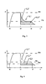
- Figure 3 shows the graph of the trend of the pressure in the traditional compressor as a function of time during an operation cycle. At time t0 the compressor is actuated and in on load operation mode makes the pressure rise fast up to the maximum value set PM, which is reached at time t1.
- the compressor operates in off load mode and the pressure decreases slowly due to depressurisation of the tank of the compressor until the pressure Pm is reached, which is approximately 2-3 relative bars.
- the compressor maintains that pressure until the preset time t2, then de-actuates and the pressure returns to the ambient value.
- the interval of time t2-t1 is preset by the user and changes according to the applications.
- the work performed by the compressor is strictly proportional to the pressure inside the compressor and therefore an area L1 of spurious work can be seen wherein the compressor progressively absorbs through re-compression and friction from 70% to 25% of the power absorbed in on load operation mode, which can be identified as the sub-area L1' and wherein the compressor re-compresses air at the pressure Pm and absorbs 25% of the power which it absorbs in on load operation mode which can be identified with the sub-area L1".
- Figure 4 instead shows a graph like that in Figure 3 yet relating to the compressor according to the present invention.
- the spurious work L2 in this case, relates to the work of re-compression at the pressure Pm' lower than Pm.
- there is a total saving of the work of re-compression relating to the sub-area L1' of Figure 3 and a considerable reduction in the work of re-compression at lower pressure equal to the difference L1 "-L2.
- the present invention also relates to a method for increasing the working efficiency of a generic rotary compressor, of the type provided with a high-pressure chamber.
- This method consists of adding a second, low-pressure chamber and means for selective deviation of the delivery flow in the first, high-pressure chamber or alternatively in the second, low-pressure chamber.
- the means for deviation of the flow can be a three-way valve placed downstream of the delivery.
- the first chamber will be a high-pressure air-oil separation tank and the second chamber will be a low-pressure oil-air separation tank, both provided with an autonomous oil recirculation line at high and low pressure respectively.
Landscapes
- Engineering & Computer Science (AREA)
- Mechanical Engineering (AREA)
- General Engineering & Computer Science (AREA)
- Applications Or Details Of Rotary Compressors (AREA)
Claims (9)
- Druckluftanlage, bestehend aus einem mindestens eine Verdichtungskammer umfassenden Rotationsverdichter (1), ausgerüstet mit einem Lufteinlass (2) und einem Zufluss-Luft-Öl-Gemenge- oder Luftablass (3), einem gesteuerten Ventil oder dgl. für die Schliessung des Einlasses im Nulllastbetrieb, einem ersten Hochdruckbehälter (4), d.h. arbeitend bei dem typischen Betriebsdruck des Verdichters im Volllastbetrieb, einem zweiten Niederdruckbehälter (6), d.h. arbeitend bei einem dem atmosphärischen Druck ähnlichen Druckwert, weiters Rohrleitungen, welche genannten Ablass (3) mit genanntem Hochdruckbehälter (4) durch eine Zuführungsleitung (5) verbinden und genannten Ablass (3) mit genanntem Niederdruckbehälter (6) durch eine Hilfsleitung (7) verbinden, einem dem Ablass (3) nachgelagerten und sowohl mit der Zuführungsleitung (5) als mit der Hilfsleitung (7) verbundenen gesteuerten 3-Weg-Ventil oder dgl., durch das der Strom der verdichteten Flüssigkeiten entweder in die Niederdruck- oder in die Hochdruckbehälter gerichtet werden kann, dadurch gekennzeichnet, dass während des Vorgangs im Volllastbetrieb genanntes 3-Weg-Ventil (8) die Zuführungsleitung (5) offen und die Hilfsleitung (7) geschlossen hält, so dass der Verdichter (1) Luft oder ein Druckgemenge an genannten Hochdruckbehälter (4) liefert und in der während des Vorgangs im Nulllastbetrieb das 3-Weg-Ventil (8) die Zuführungsleitung (5) schliesst und die Hilfsleitung (7) öffnet, sodass der Verdichter (1) eine erneute Kompression durch den Austausch des Niederdruckgemenges oder der Luft mit genanntem Niederdruckbehälter (6) durchführt.
- Druckluftanlage nach Anspruch 1, in der der Verdichter (1) ölgeschmierter Art ist und sowohl der genannter Hochdruck- (4) als der Niederdruckbehälter (6) Luft-Öl-Trennbehälter sind.
- Druckluftanlage nach Anspruch 2, in der der genannter Hochdrucktrennbehälter (4) an eine Leitung (9) für die Rückführung der Öls bei Hochdruck angeschlossen ist und der zweite Niederdrucktrennbehälter (6) an eine Leitung (11) für die Rückführung des Öls bei Niederdruck angeschlossen ist.
- Druckluftanlage nach Anspruch 3, in der die Leitungen (9, 11) für die Rückführung des Öls bei Hoch- und Niederdruck an Mitteln für das wahlweise Einspritzen des Öls in den Verdichter (1) zusammentreffen.
- Druckluftanlage nach Anspruch 4, in der diese Mitteln für das wahlweise Einspritzen des Öls aus mindestens einem zweiten den genannten Leitungen (9, 11) vorgelagerten 3-Weg-Ventil (12) für die Rückführung des Öls bei Hoch- und Niederdruck bestehen.
- Druckluftanlage nach Anspruch 5, in der während des Vorgangs im Volllastbetrieb das mindestens zweite 3-Weg-Ventil (12) die Leitung (9) für die Rückführung des Öls bei Hochdruck offen und die Leitung (12) für die Rückführung des Öls bei Niederdruck geschlossen hält, während beim Vorgang im Nulllastbetrieb genanntes mindestens zweite 3-Weg-Ventil (12) die Leitung (9) für die Rückführung des Öls bei Hochdruck schliesst und die Leitung (11) für die Rückführung des Öls bei Niederdruck öffnet.
- Verfahren zum Verbessern der Arbeitseffizienz eines Rotationsverdichters (1) nach Oberbegriff des Anspruchs 1, in dem eine wahlweise Umleitung des Zuführungsstroms in den ersten Hochdruckbehälter (4) des Verdichters im Volllastbetrieb oder wahlweise in den mindestens zweiten Niederdruckbehälter (6) des Verdichters im Nulllastbetrieb vorhanden ist.
- Verfahren nach Anspruch 7, in dem im Fall von ölgeschmierten Verdichtern (1) der Hochdruckbehälter (4) und der mindestens zweite Niederdruckbehälter (6) Luft-Öl-Trennbehälter sind, ausgestattet mit einer unabhängigen Leitung (9, 11) für die Rückführung des Öls bei Hoch- bzw. Niederdruck.
- Verfahren nach Anspruch 8, in dem genannte Leitungen (9, 11) für die Rückführung des Öls bei Hoch- und Niederdruck an Mitteln für das wahlweise Einspritzen von Öl in den Verdichter (1) zusammenlaufen.
Applications Claiming Priority (1)
| Application Number | Priority Date | Filing Date | Title |
|---|---|---|---|
| IT002406A ITMI20052406A1 (it) | 2005-12-16 | 2005-12-16 | Compressore rotativo ad efficienza di esercizio migliorata e relativo metodo |
Publications (2)
| Publication Number | Publication Date |
|---|---|
| EP1798416A1 EP1798416A1 (de) | 2007-06-20 |
| EP1798416B1 true EP1798416B1 (de) | 2009-04-22 |
Family
ID=37831438
Family Applications (1)
| Application Number | Title | Priority Date | Filing Date |
|---|---|---|---|
| EP06025093A Active EP1798416B1 (de) | 2005-12-16 | 2006-12-05 | Rotationsverdichter mit verbesserter Leistung und dazugehöriges Verfahren |
Country Status (4)
| Country | Link |
|---|---|
| EP (1) | EP1798416B1 (de) |
| AT (1) | ATE429582T1 (de) |
| DE (1) | DE602006006399D1 (de) |
| IT (1) | ITMI20052406A1 (de) |
Cited By (1)
| Publication number | Priority date | Publication date | Assignee | Title |
|---|---|---|---|---|
| WO2024211618A3 (en) * | 2023-04-05 | 2024-11-28 | Doosan Bobcat North America, Inc. | Secondary airflow paths for air compressors |
Families Citing this family (3)
| Publication number | Priority date | Publication date | Assignee | Title |
|---|---|---|---|---|
| US9618158B2 (en) | 2011-05-02 | 2017-04-11 | New Gas Industries, L.L.C. | Method and apparatus for compressing gas in a plurality of stages to a storage tank array having a plurality of storage tanks |
| US10551001B2 (en) | 2015-09-03 | 2020-02-04 | J-W Power Company | Flow control system |
| GB2596608A (en) * | 2020-06-29 | 2022-01-05 | Leybold France S A S | Supplying lubricant to a lubricant sealed pump |
Family Cites Families (7)
| Publication number | Priority date | Publication date | Assignee | Title |
|---|---|---|---|---|
| GB613303A (en) * | 1946-06-18 | 1948-11-24 | Bendix Westinghouse Automotive | Improvements in gaseous fluid pressure supply systems |
| JPS62178784A (ja) * | 1986-01-30 | 1987-08-05 | Hino Motors Ltd | エアコンプレツサ装置 |
| JPH0381595A (ja) * | 1989-08-23 | 1991-04-05 | Hitachi Ltd | 給油式スクリュー圧縮機の容量制御装置 |
| JPH05133374A (ja) * | 1991-11-12 | 1993-05-28 | Hitachi Ltd | ヘリウムガス圧縮装置 |
| JP3668421B2 (ja) * | 2000-11-01 | 2005-07-06 | Smc株式会社 | 空気圧縮装置 |
| JP2004330839A (ja) * | 2003-05-06 | 2004-11-25 | Nissan Diesel Motor Co Ltd | 圧縮空気供給装置 |
| DE10347072A1 (de) * | 2003-10-09 | 2005-05-04 | Wabco Gmbh & Co Ohg | Verfahren und Anordnung zur Druckerhöhung von Gasen |
-
2005
- 2005-12-16 IT IT002406A patent/ITMI20052406A1/it unknown
-
2006
- 2006-12-05 EP EP06025093A patent/EP1798416B1/de active Active
- 2006-12-05 DE DE602006006399T patent/DE602006006399D1/de active Active
- 2006-12-05 AT AT06025093T patent/ATE429582T1/de not_active IP Right Cessation
Cited By (2)
| Publication number | Priority date | Publication date | Assignee | Title |
|---|---|---|---|---|
| WO2024211618A3 (en) * | 2023-04-05 | 2024-11-28 | Doosan Bobcat North America, Inc. | Secondary airflow paths for air compressors |
| US12410799B2 (en) | 2023-04-05 | 2025-09-09 | Doosan Bobcat North America, Inc. | Secondary airflow paths for air compressors |
Also Published As
| Publication number | Publication date |
|---|---|
| DE602006006399D1 (de) | 2009-06-04 |
| EP1798416A1 (de) | 2007-06-20 |
| ATE429582T1 (de) | 2009-05-15 |
| ITMI20052406A1 (it) | 2007-06-17 |
Similar Documents
| Publication | Publication Date | Title |
|---|---|---|
| CN101163887B (zh) | 用于在停止期间控制变速压缩机的系统和方法 | |
| US4335582A (en) | Unloading control system for helical screw compressor refrigeration system | |
| US8844290B2 (en) | Steam system | |
| CN101790644A (zh) | 低温泵系统 | |
| US8522523B2 (en) | Steam system | |
| US20230279857A1 (en) | Method for controlling a rotary screw compressor | |
| KR101253086B1 (ko) | 흡입 공기 제어장치를 통한 에너지 절감형 스크류 공기압축기 장치 | |
| US7607899B2 (en) | Compressor with capacity control | |
| CN101627268A (zh) | 通过降低吸气压力提高效率的脉宽调制 | |
| CN108954884A (zh) | 一种冷热双制螺杆压缩机组 | |
| CN112648168B (zh) | 往返式压缩膨胀机 | |
| CN101769662B (zh) | 冷冻装置的变频节能温控装置 | |
| EP1798416A1 (de) | Rotationsverdichter mit verbesserter Leistung und dazugehöriges Verfahren | |
| JP2009144685A (ja) | 油冷式スクリュー圧縮機 | |
| KR101319192B1 (ko) | 증기 구동식 압축 장치 | |
| WO2019186861A1 (ja) | 気体圧縮機 | |
| EP2417357A1 (de) | Insbesondere zur parallelverbindung in kompressionseinheiten geeigneter schraubenkompressor | |
| JP5033400B2 (ja) | 油冷式スクリュ圧縮機の負荷軽減方法及び油冷式スクリュ圧縮機 | |
| CN207609560U (zh) | 平衡型罗茨真空泵系统 | |
| JP5412243B2 (ja) | ブースタ圧縮機 | |
| CN100408860C (zh) | 旋叶式压缩机排量自动调节机构 | |
| JP7461255B2 (ja) | 圧縮機における圧縮気体冷却方法及び圧縮気体冷却装置 | |
| CN108397978A (zh) | 一种冷冻式干燥机 | |
| JP2005083214A (ja) | 圧縮機ユニット | |
| AU2023424008A1 (en) | Compressor unit |
Legal Events
| Date | Code | Title | Description |
|---|---|---|---|
| PUAI | Public reference made under article 153(3) epc to a published international application that has entered the european phase |
Free format text: ORIGINAL CODE: 0009012 |
|
| AK | Designated contracting states |
Kind code of ref document: A1 Designated state(s): AT BE BG CH CY CZ DE DK EE ES FI FR GB GR HU IE IS IT LI LT LU LV MC NL PL PT RO SE SI SK TR |
|
| AX | Request for extension of the european patent |
Extension state: AL BA HR MK YU |
|
| 17P | Request for examination filed |
Effective date: 20071114 |
|
| AKX | Designation fees paid |
Designated state(s): AT BE BG CH CY CZ DE DK EE ES FI FR GB GR HU IE IS IT LI LT LU LV MC NL PL PT RO SE SI SK TR |
|
| GRAP | Despatch of communication of intention to grant a patent |
Free format text: ORIGINAL CODE: EPIDOSNIGR1 |
|
| GRAS | Grant fee paid |
Free format text: ORIGINAL CODE: EPIDOSNIGR3 |
|
| GRAA | (expected) grant |
Free format text: ORIGINAL CODE: 0009210 |
|
| AK | Designated contracting states |
Kind code of ref document: B1 Designated state(s): AT BE BG CH CY CZ DE DK EE ES FI FR GB GR HU IE IS IT LI LT LU LV MC NL PL PT RO SE SI SK TR |
|
| REG | Reference to a national code |
Ref country code: GB Ref legal event code: FG4D |
|
| REG | Reference to a national code |
Ref country code: CH Ref legal event code: EP |
|
| REG | Reference to a national code |
Ref country code: IE Ref legal event code: FG4D |
|
| REF | Corresponds to: |
Ref document number: 602006006399 Country of ref document: DE Date of ref document: 20090604 Kind code of ref document: P |
|
| NLV1 | Nl: lapsed or annulled due to failure to fulfill the requirements of art. 29p and 29m of the patents act | ||
| PG25 | Lapsed in a contracting state [announced via postgrant information from national office to epo] |
Ref country code: ES Free format text: LAPSE BECAUSE OF FAILURE TO SUBMIT A TRANSLATION OF THE DESCRIPTION OR TO PAY THE FEE WITHIN THE PRESCRIBED TIME-LIMIT Effective date: 20090802 Ref country code: AT Free format text: LAPSE BECAUSE OF FAILURE TO SUBMIT A TRANSLATION OF THE DESCRIPTION OR TO PAY THE FEE WITHIN THE PRESCRIBED TIME-LIMIT Effective date: 20090422 Ref country code: PT Free format text: LAPSE BECAUSE OF FAILURE TO SUBMIT A TRANSLATION OF THE DESCRIPTION OR TO PAY THE FEE WITHIN THE PRESCRIBED TIME-LIMIT Effective date: 20090822 Ref country code: LT Free format text: LAPSE BECAUSE OF FAILURE TO SUBMIT A TRANSLATION OF THE DESCRIPTION OR TO PAY THE FEE WITHIN THE PRESCRIBED TIME-LIMIT Effective date: 20090422 Ref country code: FI Free format text: LAPSE BECAUSE OF FAILURE TO SUBMIT A TRANSLATION OF THE DESCRIPTION OR TO PAY THE FEE WITHIN THE PRESCRIBED TIME-LIMIT Effective date: 20090422 |
|
| PG25 | Lapsed in a contracting state [announced via postgrant information from national office to epo] |
Ref country code: PL Free format text: LAPSE BECAUSE OF FAILURE TO SUBMIT A TRANSLATION OF THE DESCRIPTION OR TO PAY THE FEE WITHIN THE PRESCRIBED TIME-LIMIT Effective date: 20090422 Ref country code: LV Free format text: LAPSE BECAUSE OF FAILURE TO SUBMIT A TRANSLATION OF THE DESCRIPTION OR TO PAY THE FEE WITHIN THE PRESCRIBED TIME-LIMIT Effective date: 20090422 Ref country code: NL Free format text: LAPSE BECAUSE OF FAILURE TO SUBMIT A TRANSLATION OF THE DESCRIPTION OR TO PAY THE FEE WITHIN THE PRESCRIBED TIME-LIMIT Effective date: 20090422 Ref country code: SE Free format text: LAPSE BECAUSE OF FAILURE TO SUBMIT A TRANSLATION OF THE DESCRIPTION OR TO PAY THE FEE WITHIN THE PRESCRIBED TIME-LIMIT Effective date: 20090722 Ref country code: SI Free format text: LAPSE BECAUSE OF FAILURE TO SUBMIT A TRANSLATION OF THE DESCRIPTION OR TO PAY THE FEE WITHIN THE PRESCRIBED TIME-LIMIT Effective date: 20090422 Ref country code: IS Free format text: LAPSE BECAUSE OF FAILURE TO SUBMIT A TRANSLATION OF THE DESCRIPTION OR TO PAY THE FEE WITHIN THE PRESCRIBED TIME-LIMIT Effective date: 20090822 |
|
| PG25 | Lapsed in a contracting state [announced via postgrant information from national office to epo] |
Ref country code: RO Free format text: LAPSE BECAUSE OF FAILURE TO SUBMIT A TRANSLATION OF THE DESCRIPTION OR TO PAY THE FEE WITHIN THE PRESCRIBED TIME-LIMIT Effective date: 20090422 Ref country code: EE Free format text: LAPSE BECAUSE OF FAILURE TO SUBMIT A TRANSLATION OF THE DESCRIPTION OR TO PAY THE FEE WITHIN THE PRESCRIBED TIME-LIMIT Effective date: 20090422 Ref country code: CZ Free format text: LAPSE BECAUSE OF FAILURE TO SUBMIT A TRANSLATION OF THE DESCRIPTION OR TO PAY THE FEE WITHIN THE PRESCRIBED TIME-LIMIT Effective date: 20090422 Ref country code: DK Free format text: LAPSE BECAUSE OF FAILURE TO SUBMIT A TRANSLATION OF THE DESCRIPTION OR TO PAY THE FEE WITHIN THE PRESCRIBED TIME-LIMIT Effective date: 20090422 |
|
| PG25 | Lapsed in a contracting state [announced via postgrant information from national office to epo] |
Ref country code: SK Free format text: LAPSE BECAUSE OF FAILURE TO SUBMIT A TRANSLATION OF THE DESCRIPTION OR TO PAY THE FEE WITHIN THE PRESCRIBED TIME-LIMIT Effective date: 20090422 |
|
| PLBE | No opposition filed within time limit |
Free format text: ORIGINAL CODE: 0009261 |
|
| STAA | Information on the status of an ep patent application or granted ep patent |
Free format text: STATUS: NO OPPOSITION FILED WITHIN TIME LIMIT |
|
| 26N | No opposition filed |
Effective date: 20100125 |
|
| PG25 | Lapsed in a contracting state [announced via postgrant information from national office to epo] |
Ref country code: BG Free format text: LAPSE BECAUSE OF FAILURE TO SUBMIT A TRANSLATION OF THE DESCRIPTION OR TO PAY THE FEE WITHIN THE PRESCRIBED TIME-LIMIT Effective date: 20090722 |
|
| PG25 | Lapsed in a contracting state [announced via postgrant information from national office to epo] |
Ref country code: MC Free format text: LAPSE BECAUSE OF NON-PAYMENT OF DUE FEES Effective date: 20100701 |
|
| REG | Reference to a national code |
Ref country code: IE Ref legal event code: MM4A |
|
| PG25 | Lapsed in a contracting state [announced via postgrant information from national office to epo] |
Ref country code: IE Free format text: LAPSE BECAUSE OF NON-PAYMENT OF DUE FEES Effective date: 20091205 Ref country code: GR Free format text: LAPSE BECAUSE OF FAILURE TO SUBMIT A TRANSLATION OF THE DESCRIPTION OR TO PAY THE FEE WITHIN THE PRESCRIBED TIME-LIMIT Effective date: 20090723 |
|
| PG25 | Lapsed in a contracting state [announced via postgrant information from national office to epo] |
Ref country code: LU Free format text: LAPSE BECAUSE OF NON-PAYMENT OF DUE FEES Effective date: 20091205 |
|
| PG25 | Lapsed in a contracting state [announced via postgrant information from national office to epo] |
Ref country code: HU Free format text: LAPSE BECAUSE OF FAILURE TO SUBMIT A TRANSLATION OF THE DESCRIPTION OR TO PAY THE FEE WITHIN THE PRESCRIBED TIME-LIMIT Effective date: 20091023 |
|
| REG | Reference to a national code |
Ref country code: CH Ref legal event code: PL |
|
| PG25 | Lapsed in a contracting state [announced via postgrant information from national office to epo] |
Ref country code: TR Free format text: LAPSE BECAUSE OF FAILURE TO SUBMIT A TRANSLATION OF THE DESCRIPTION OR TO PAY THE FEE WITHIN THE PRESCRIBED TIME-LIMIT Effective date: 20090422 |
|
| PG25 | Lapsed in a contracting state [announced via postgrant information from national office to epo] |
Ref country code: CY Free format text: LAPSE BECAUSE OF FAILURE TO SUBMIT A TRANSLATION OF THE DESCRIPTION OR TO PAY THE FEE WITHIN THE PRESCRIBED TIME-LIMIT Effective date: 20090422 |
|
| PG25 | Lapsed in a contracting state [announced via postgrant information from national office to epo] |
Ref country code: LI Free format text: LAPSE BECAUSE OF NON-PAYMENT OF DUE FEES Effective date: 20101231 Ref country code: CH Free format text: LAPSE BECAUSE OF NON-PAYMENT OF DUE FEES Effective date: 20101231 |
|
| REG | Reference to a national code |
Ref country code: DE Ref legal event code: R082 Ref document number: 602006006399 Country of ref document: DE Representative=s name: PATENTANWAELTE WEICKMANN & WEICKMANN, DE Ref country code: DE Ref legal event code: R082 Ref document number: 602006006399 Country of ref document: DE Representative=s name: WEICKMANN & WEICKMANN PATENTANWAELTE - RECHTSA, DE Ref country code: DE Ref legal event code: R082 Ref document number: 602006006399 Country of ref document: DE Representative=s name: WEICKMANN & WEICKMANN PATENT- UND RECHTSANWAEL, DE |
|
| REG | Reference to a national code |
Ref country code: FR Ref legal event code: PLFP Year of fee payment: 10 |
|
| REG | Reference to a national code |
Ref country code: FR Ref legal event code: PLFP Year of fee payment: 11 |
|
| REG | Reference to a national code |
Ref country code: FR Ref legal event code: PLFP Year of fee payment: 12 |
|
| PGFP | Annual fee paid to national office [announced via postgrant information from national office to epo] |
Ref country code: BE Payment date: 20221228 Year of fee payment: 17 |
|
| REG | Reference to a national code |
Ref country code: BE Ref legal event code: MM Effective date: 20231231 |
|
| PG25 | Lapsed in a contracting state [announced via postgrant information from national office to epo] |
Ref country code: BE Free format text: LAPSE BECAUSE OF NON-PAYMENT OF DUE FEES Effective date: 20231231 |
|
| PG25 | Lapsed in a contracting state [announced via postgrant information from national office to epo] |
Ref country code: BE Free format text: LAPSE BECAUSE OF NON-PAYMENT OF DUE FEES Effective date: 20231231 |
|
| PGFP | Annual fee paid to national office [announced via postgrant information from national office to epo] |
Ref country code: GB Payment date: 20251229 Year of fee payment: 20 |
|
| PGFP | Annual fee paid to national office [announced via postgrant information from national office to epo] |
Ref country code: FR Payment date: 20251223 Year of fee payment: 20 |
|
| PGFP | Annual fee paid to national office [announced via postgrant information from national office to epo] |
Ref country code: DE Payment date: 20251230 Year of fee payment: 20 |
|
| PGFP | Annual fee paid to national office [announced via postgrant information from national office to epo] |
Ref country code: IT Payment date: 20251229 Year of fee payment: 20 |