EP1798511B1 - Dispositif de refroidissement d'un écoulement de gaz - Google Patents
Dispositif de refroidissement d'un écoulement de gaz Download PDFInfo
- Publication number
- EP1798511B1 EP1798511B1 EP06025787A EP06025787A EP1798511B1 EP 1798511 B1 EP1798511 B1 EP 1798511B1 EP 06025787 A EP06025787 A EP 06025787A EP 06025787 A EP06025787 A EP 06025787A EP 1798511 B1 EP1798511 B1 EP 1798511B1
- Authority
- EP
- European Patent Office
- Prior art keywords
- exchanger means
- vibration generator
- gas flow
- deposits
- housing
- Prior art date
- Legal status (The legal status is an assumption and is not a legal conclusion. Google has not performed a legal analysis and makes no representation as to the accuracy of the status listed.)
- Not-in-force
Links
Images


Classifications
-
- F—MECHANICAL ENGINEERING; LIGHTING; HEATING; WEAPONS; BLASTING
- F28—HEAT EXCHANGE IN GENERAL
- F28G—CLEANING OF INTERNAL OR EXTERNAL SURFACES OF HEAT-EXCHANGE OR HEAT-TRANSFER CONDUITS, e.g. WATER TUBES OR BOILERS
- F28G7/00—Cleaning by vibration or pressure waves
-
- F—MECHANICAL ENGINEERING; LIGHTING; HEATING; WEAPONS; BLASTING
- F02—COMBUSTION ENGINES; HOT-GAS OR COMBUSTION-PRODUCT ENGINE PLANTS
- F02B—INTERNAL-COMBUSTION PISTON ENGINES; COMBUSTION ENGINES IN GENERAL
- F02B29/00—Engines characterised by provision for charging or scavenging not provided for in groups F02B25/00, F02B27/00 or F02B33/00 - F02B39/00; Details thereof
- F02B29/04—Cooling of air intake supply
- F02B29/045—Constructional details of the heat exchangers, e.g. pipes, plates, ribs, insulation, materials, or manufacturing and assembly
- F02B29/0462—Liquid cooled heat exchangers
-
- F—MECHANICAL ENGINEERING; LIGHTING; HEATING; WEAPONS; BLASTING
- F02—COMBUSTION ENGINES; HOT-GAS OR COMBUSTION-PRODUCT ENGINE PLANTS
- F02B—INTERNAL-COMBUSTION PISTON ENGINES; COMBUSTION ENGINES IN GENERAL
- F02B29/00—Engines characterised by provision for charging or scavenging not provided for in groups F02B25/00, F02B27/00 or F02B33/00 - F02B39/00; Details thereof
- F02B29/04—Cooling of air intake supply
- F02B29/045—Constructional details of the heat exchangers, e.g. pipes, plates, ribs, insulation, materials, or manufacturing and assembly
- F02B29/0475—Constructional details of the heat exchangers, e.g. pipes, plates, ribs, insulation, materials, or manufacturing and assembly the intake air cooler being combined with another device, e.g. heater, valve, compressor, filter or EGR cooler, or being assembled on a special engine location
-
- F—MECHANICAL ENGINEERING; LIGHTING; HEATING; WEAPONS; BLASTING
- F02—COMBUSTION ENGINES; HOT-GAS OR COMBUSTION-PRODUCT ENGINE PLANTS
- F02M—SUPPLYING COMBUSTION ENGINES IN GENERAL WITH COMBUSTIBLE MIXTURES OR CONSTITUENTS THEREOF
- F02M26/00—Engine-pertinent apparatus for adding exhaust gases to combustion-air, main fuel or fuel-air mixture, e.g. by exhaust gas recirculation [EGR] systems
- F02M26/13—Arrangement or layout of EGR passages, e.g. in relation to specific engine parts or for incorporation of accessories
- F02M26/22—Arrangement or layout of EGR passages, e.g. in relation to specific engine parts or for incorporation of accessories with coolers in the recirculation passage
- F02M26/29—Constructional details of the coolers, e.g. pipes, plates, ribs, insulation or materials
- F02M26/30—Connections of coolers to other devices, e.g. to valves, heaters, compressors or filters; Coolers characterised by their location on the engine
-
- F—MECHANICAL ENGINEERING; LIGHTING; HEATING; WEAPONS; BLASTING
- F02—COMBUSTION ENGINES; HOT-GAS OR COMBUSTION-PRODUCT ENGINE PLANTS
- F02M—SUPPLYING COMBUSTION ENGINES IN GENERAL WITH COMBUSTIBLE MIXTURES OR CONSTITUENTS THEREOF
- F02M26/00—Engine-pertinent apparatus for adding exhaust gases to combustion-air, main fuel or fuel-air mixture, e.g. by exhaust gas recirculation [EGR] systems
- F02M26/13—Arrangement or layout of EGR passages, e.g. in relation to specific engine parts or for incorporation of accessories
- F02M26/22—Arrangement or layout of EGR passages, e.g. in relation to specific engine parts or for incorporation of accessories with coolers in the recirculation passage
- F02M26/29—Constructional details of the coolers, e.g. pipes, plates, ribs, insulation or materials
- F02M26/32—Liquid-cooled heat exchangers
-
- F—MECHANICAL ENGINEERING; LIGHTING; HEATING; WEAPONS; BLASTING
- F02—COMBUSTION ENGINES; HOT-GAS OR COMBUSTION-PRODUCT ENGINE PLANTS
- F02M—SUPPLYING COMBUSTION ENGINES IN GENERAL WITH COMBUSTIBLE MIXTURES OR CONSTITUENTS THEREOF
- F02M26/00—Engine-pertinent apparatus for adding exhaust gases to combustion-air, main fuel or fuel-air mixture, e.g. by exhaust gas recirculation [EGR] systems
- F02M26/13—Arrangement or layout of EGR passages, e.g. in relation to specific engine parts or for incorporation of accessories
- F02M26/40—Arrangement or layout of EGR passages, e.g. in relation to specific engine parts or for incorporation of accessories with timing means in the recirculation passage, e.g. cyclically operating valves or regenerators; with arrangements involving pressure pulsations
-
- F—MECHANICAL ENGINEERING; LIGHTING; HEATING; WEAPONS; BLASTING
- F02—COMBUSTION ENGINES; HOT-GAS OR COMBUSTION-PRODUCT ENGINE PLANTS
- F02M—SUPPLYING COMBUSTION ENGINES IN GENERAL WITH COMBUSTIBLE MIXTURES OR CONSTITUENTS THEREOF
- F02M26/00—Engine-pertinent apparatus for adding exhaust gases to combustion-air, main fuel or fuel-air mixture, e.g. by exhaust gas recirculation [EGR] systems
- F02M26/50—Arrangements or methods for preventing or reducing deposits, corrosion or wear caused by impurities
-
- F—MECHANICAL ENGINEERING; LIGHTING; HEATING; WEAPONS; BLASTING
- F01—MACHINES OR ENGINES IN GENERAL; ENGINE PLANTS IN GENERAL; STEAM ENGINES
- F01N—GAS-FLOW SILENCERS OR EXHAUST APPARATUS FOR MACHINES OR ENGINES IN GENERAL; GAS-FLOW SILENCERS OR EXHAUST APPARATUS FOR INTERNAL-COMBUSTION ENGINES
- F01N2240/00—Combination or association of two or more different exhaust treating devices, or of at least one such device with an auxiliary device, not covered by indexing codes F01N2230/00 or F01N2250/00, one of the devices being
- F01N2240/02—Combination or association of two or more different exhaust treating devices, or of at least one such device with an auxiliary device, not covered by indexing codes F01N2230/00 or F01N2250/00, one of the devices being a heat exchanger
-
- F—MECHANICAL ENGINEERING; LIGHTING; HEATING; WEAPONS; BLASTING
- F01—MACHINES OR ENGINES IN GENERAL; ENGINE PLANTS IN GENERAL; STEAM ENGINES
- F01N—GAS-FLOW SILENCERS OR EXHAUST APPARATUS FOR MACHINES OR ENGINES IN GENERAL; GAS-FLOW SILENCERS OR EXHAUST APPARATUS FOR INTERNAL-COMBUSTION ENGINES
- F01N3/00—Exhaust or silencing apparatus having means for purifying, rendering innocuous, or otherwise treating exhaust
- F01N3/01—Exhaust or silencing apparatus having means for purifying, rendering innocuous, or otherwise treating exhaust by means of electric or electrostatic separators
-
- F—MECHANICAL ENGINEERING; LIGHTING; HEATING; WEAPONS; BLASTING
- F28—HEAT EXCHANGE IN GENERAL
- F28D—HEAT-EXCHANGE APPARATUS, NOT PROVIDED FOR IN ANOTHER SUBCLASS, IN WHICH THE HEAT-EXCHANGE MEDIA DO NOT COME INTO DIRECT CONTACT
- F28D7/00—Heat-exchange apparatus having stationary tubular conduit assemblies for both heat-exchange media, the media being in contact with different sides of a conduit wall
- F28D7/16—Heat-exchange apparatus having stationary tubular conduit assemblies for both heat-exchange media, the media being in contact with different sides of a conduit wall the conduits being arranged in parallel spaced relation
- F28D7/1684—Heat-exchange apparatus having stationary tubular conduit assemblies for both heat-exchange media, the media being in contact with different sides of a conduit wall the conduits being arranged in parallel spaced relation the conduits having a non-circular cross-section
-
- Y—GENERAL TAGGING OF NEW TECHNOLOGICAL DEVELOPMENTS; GENERAL TAGGING OF CROSS-SECTIONAL TECHNOLOGIES SPANNING OVER SEVERAL SECTIONS OF THE IPC; TECHNICAL SUBJECTS COVERED BY FORMER USPC CROSS-REFERENCE ART COLLECTIONS [XRACs] AND DIGESTS
- Y02—TECHNOLOGIES OR APPLICATIONS FOR MITIGATION OR ADAPTATION AGAINST CLIMATE CHANGE
- Y02T—CLIMATE CHANGE MITIGATION TECHNOLOGIES RELATED TO TRANSPORTATION
- Y02T10/00—Road transport of goods or passengers
- Y02T10/10—Internal combustion engine [ICE] based vehicles
- Y02T10/12—Improving ICE efficiencies
Definitions
- the present invention relates to a device for cooling a gas stream according to the preamble of claim 1.
- DE-A1-19801 753 describes such a device.
- Exhaust gas heat exchangers are known from the prior art.
- exhaust gas coolers are known which are used in engines of motor vehicles for the purpose of exhaust gas recirculation.
- the thermal conductivity is reduced, and with a corresponding increase in deposits of the flow cross-section is reduced.
- exhaust gas heat exchangers for motor vehicles have therefore been sufficiently dimensioned so that even in the presence of deposits a sufficient flow cross-section for the exhaust gas flow and a sufficient thermal performance of the components remains.
- the deposits in particular in the form of corrosive condensate, can lead to corrosive damage to the heat exchange material until leaks occur.
- the device is an exhaust gas heat exchanger of an internal combustion engine, in particular of a motor vehicle.
- the usually variable operating conditions in internal combustion engines and the particular limited installation space in motor vehicles give special advantages when using a device according to the invention with respect to the prevention of deposits.
- the device may also be a charge air cooler, in particular an internal combustion engine of a motor vehicle. Also in the cooling of compressed ambient air deposits can form, which can lead to impair over a long service life.
- the device preferably has a housing which surrounds the exchanger means.
- the fluid is a liquid conducted in the housing.
- the vibration transmitter can preferably be arranged either inside the housing or outside the housing. In an arrangement within the housing results in a particularly effective vibration transmission to the exchange means, while in an arrangement outside the housing has the advantage of a good maintenance access to the vibration sensors.
- a plurality of vibration sensors in particular at least three vibration sensors, are arranged on the device.
- the frequency range of the mechanical vibrations is essentially in the ultrasonic range.
- the frequency range is above 30,000 Hz, preferably in the range of 40,000 Hz. This fairly high frequency range has the advantage that strong cavitation, which could lead to damage to the Tauscherstoffwandungen is avoided.
- the mechanical vibrations may have a plurality of main excitation frequencies. It has been shown that when using multiple excitation frequencies, a particularly good cleaning effect can be achieved by mechanical vibrations and / or ultrasound.
- the at least one vibration sensor is only temporarily in operation, and in particular advantageous may be provided that it is operated pulsed.
- the at least one vibration generator is operated as a function of a detectable via a measured variable degree of contamination of the exchange means, so that an unnecessary operation of the vibration generator is avoided.
- the measured variable can be a pressure difference across the device be by means of a simple way an increased, caused by deposits flow resistance of the device for cooling an exhaust gas flow is displayed.
- the exchange means have a ribbing in contact with the exhaust stream and / or introduction of forms such as winglets on.
- a ribbing not only improves the heat exchanger performance, but can also provide a suitable form of cleaning by applying mechanical vibrations feed.
- the exchange means may have a surface treatment to reduce deposits, which is a complementary to the vibration generators protection against deposits.
- the walls may have a coating, for example made of Teflon or another smooth and sufficiently temperature-resistant material, in particular with low surface energy.
- the walls can also be substantially polished.
- the vibration generator comprises a piezoelectric plastic, in particular polyvinylidene fluoride (PVDF).
- PVDF polyvinylidene fluoride
- the vibration transmitter can also, depending on the requirements, comprise a piezoelectric ceramic or a piezoelectric composite material, in particular a nanocomposite made of plastic and ceramic particles.
- the device has a formation for the localized accumulation of deposits, in particular condensate of the gas stream, wherein the vibration generator is arranged in the region of the accumulation of deposits.
- the vibration generator is arranged in the region of the accumulation of deposits.
- a concentration of the condensate is achieved in one place and a particularly effective sputtering and removal by the vibrator.
- the vibration sensor is arranged in the region of an exit of the gas flow from the exchange means. This is the one with a variety of constructions such as For example, down-flow arrangements a geometrically particularly suitable collection point and on the other hand, the place with respect to the gas flow lowest temperature, which is conducive to both the condensate collection and the reliability of the vibration generator.
- At least the exchange means preferably consist essentially of a metal, in particular based on steel, stainless steel or aluminum.
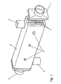
- Fig. 1 shows a shell and tube exhaust heat exchanger for a motor vehicle.
- the heat exchanger comprises an input-side diffuser 1 for supplying the exhaust gas stream, after which the exhaust gas stream flows through a bundle of parallel flat tubes 4, on the inner walls of which heat of the exhaust gas is removed.
- the flat tubes 4 are fixed on unspecified head pieces on a flat tubes 4 surrounding housing 3.
- the housing 3 also has connections 2, by means of which the housing 3 can be flowed through by a liquid coolant.
- the coolant may in particular be the coolant of a main cooling circuit of the internal combustion engine of the motor vehicle.
- the coolant flows around Actuation motor of the motor vehicle act.
- the coolant flows around the outer walls of the flat tubes 4, so that the heat released by the exhaust gas to the walls of the flat tubes 4 is dissipated via the coolant. After flowing through the flat tubes 4, the exhaust gas flow enters an outlet-side diffuser 6, whereafter it is returned to the internal combustion engine of the motor vehicle.
- the vibration sensors 5 are known per se sonotrodes for generating mechanical vibrations in the ultrasonic range.
- the main excitation frequency of the sonotrodes is about 40,000 Hz.
- the deposits can have a different consistency.
- the sonotrodes are switched on when the deposits are particularly dry and brittle due to temperature.
- the flat tubes 4 are preferably provided with inner ribs, not shown. These may be rib-like inserts in the flat tubes 4, which are materially connected to the flat tubes 4 such as soldered, welded or glued. In another embodiment, features such as winglets, in particular by a forming manufacturing process such as stamping, embossing thermoforming, etc. are introduced into the flat tubes.
- features such as winglets, in particular by a forming manufacturing process such as stamping, embossing thermoforming, etc. are introduced into the flat tubes.
- the material for the construction of exhaust gas heat exchangers in particular for the construction of the diffusers 1, 6 and the flat tubes 4 are regularly steel, especially corrosion-resistant steel such as austenitic steel.
- Fig. 2 shows a second embodiment, which is a liquid-cooled exhaust gas heat exchanger as in the first example.
- a vibration core 5 is inserted via a sealing collar 7.
- the installation position of the heat exchanger is as shown in the drawing chosen so that the exchange means 4 at the same time in the direction of the lowest region inclined walls or formations for guiding the resulting condensate form, so that at least the flowable condensate collects in this area.
- Fig. 3 shows a heat exchanger according to the invention, which may be a charge air cooler or a low-pressure exhaust gas cooler.
- the exchanger tubes 4 are directly cooled by ambient air flowing around (direct cooling).
- the inlet region 1 and the outlet region 6 are each shaped in the manner of a collector box.
- the outlet region 6 comprises by appropriate installation position and shaping its walls a collecting area for the accumulation of liquid condensate.
- a vibration transmitter 5 is arranged in a passage 8 via a sealing collar 7.
- the accumulated condensate by the suitable Positioned vibration generator can be atomized if necessary. The corrosive action of the condensate on the heat exchanger materials is thereby reduced.
- the heat exchanger in particular the exhaust gas heat exchanger, is formed from disks.
- the discs are stacked on top of each other. Between adjacent disks flow channels for a fluid such as exhaust gas and / or for a cooling medium such as water or air are formed.
- the heat exchanger is designed as a coolant radiator and / or as a charge air cooler and / or as an oil cooler and / or as a condenser for an air conditioner and / or as an evaporator for an air conditioner and / or as a gas cooler for an air conditioner.
Landscapes
- Engineering & Computer Science (AREA)
- Chemical & Material Sciences (AREA)
- Combustion & Propulsion (AREA)
- Mechanical Engineering (AREA)
- General Engineering & Computer Science (AREA)
- Physics & Mathematics (AREA)
- Thermal Sciences (AREA)
- Heat-Exchange Devices With Radiators And Conduit Assemblies (AREA)
- Exhaust-Gas Circulating Devices (AREA)
- Physical Or Chemical Processes And Apparatus (AREA)
Claims (24)
- Dispositif de refroidissement d'un flux de gaz, en particulier d'un moteur à combustion interne, comprenant :- des moyens échangeurs (4) servant au guidage d'un flux de gaz, où les moyens échangeurs (4) présentent une paroi en contact avec le flux de gaz, et- un fluide servant à circuler autour des moyens échangeurs (4), où de la chaleur provenant du flux de gaz peut être transmise au fluide,caractérisé en ce que le dispositif comprend au moins un émetteur de vibrations (5) à l'aide duquel au moins des parties des moyens échangeurs (4) peuvent être sollicitées par des vibrations mécaniques,
où les vibrations mécaniques sont appropriées pour der dépôts adhérant sur la paroi. - Dispositif selon la revendication 1, caractérisé en ce que le dispositif est un échangeur de chaleur de gaz d'échappement d'un moteur à combustion interne, en particulier d'un véhicule automobile.
- Dispositif selon la revendication 1, caractérisé en ce que le dispositif est un refroidisseur d'air de suralimentation d'un moteur à combustion interne, en particulier d'un véhicule automobile.
- Dispositif selon l'une quelconque des revendications précédentes, caractérisé en ce que le dispositif présente un carter (3) entourant les moyens échangeurs (4).
- Dispositif selon la revendication 4, caractérisé en ce que le fluide est un liquide guidé dans le carter (3).
- Dispositif selon la revendication 4 ou 5, caractérisé en ce que l'émetteur de vibrations (5) au moins au nombre de un est disposé à l'intérieur du carter (3).
- Dispositif selon la revendication 4 ou 5, caractérisé en ce que l'émetteur de vibrations (5) au moins au nombre de un est disposé à l'extérieur du carter (3).
- Dispositif selon l'une quelconque des revendications précédentes, caractérisé en ce que plusieurs émetteurs de vibrations (5), en particulier au moins trois, sont disposés sur le dispositif.
- Dispositif selon l'une quelconque des revendications précédentes, caractérisé en ce qu'une plage de fréquences des vibrations mécaniques se situe essentiellement dans la plage des ultrasons.
- Dispositif selon la revendication 9, caractérisé en ce que la plage de fréquences est supérieure à 30.000 Hz, de préférence dans la plage de 40.000 Hz.
- Dispositif selon l'une quelconque des revendications précédentes, caractérisé en ce que les vibrations mécaniques présentent une pluralité de fréquences d'excitation principales.
- Dispositif selon l'une quelconque des revendications précédentes, caractérisé en ce que l'émetteur de vibrations (5) au moins au nombre de un est en fonctionnement seulement par moments, est actionné en particulier par impulsions.
- Dispositif selon l'une quelconque des revendications précédentes, caractérisé en ce que l'émetteur de vibrations (5) au moins au nombre de un est actionné en fonction d'un degré d'encrassement des moyens échangeurs (4), pouvant être constaté par une grandeur mesurés.
- Dispositif selon la revendication 13, caractérisé en ce que la grandeur mesurée est une différence de pression au-delà du dispositif.
- Dispositif selon l'une quelconque des revendications précédentes, caractérisé en ce que les moyens échangeurs (4) présentent un ensemble d'ailettes en avec le flux de gaz d'échappement.
- Dispositif selon l'une quelconque des revendications précédentes, caractérisé en ce que les moyens échangeurs (4) présentent un traitement de surface servant à diminuer les dépots.
- Dispositif selon la revendication 16, caractérisé en ce que la paroi des moyens échangeurs (4) présente un revêtement.
- Dispositif selon la revendication 16 ou 17, caractérisé en ce que la paroi des moyens échangeurs (4) est essentiellement polie.
- Dispositif selon l'une quelconque des revendications précédentes, caractérisé en ce que l'Émetteur de vibrations (5) comprend une matière plastique piézoélectrique, en particulier du fluorure de polyvinylidène (PVDF).
- Dispositif selon l'une quelconque des revendications précédentes, caractérisé en ce que l'émetteur de vibrations (5) comprend une céramique piézoélectrique.
- Dispositif selon l'une quelconque des revendications précédentes, caractérisé en ce que l'émetteur de vibrations (5) est un matériau composite piézoélectrique, en particulier un nanocomposite.
- Dispositif selon l'une quelconque des revendications précédentes, caractérisé en ce que le dispositif présente un moulage pour l'accumulation localisée des dépôts, en particulier un condensat du flux de gaz, où l'émetteur de vibrations (5) est disposé dans la zone de l'accumulation des dépôts.
- Dispositif selon la revendication 22, caractérisé en ce que l'émetteur de vibrations (5) est disposé dans la zone d'une sortie (6) du flux de gaz provenant des moyens échangeurs (4).
- Dispositif selon l'une quelconque des revendications précédentes, caractérisé en ce qu'au moins les moyens échangeurs (4) se composent essentiellement d'un métal, en particulier à base d'acier, d'acier spécial ou d'aluminium.
Applications Claiming Priority (2)
| Application Number | Priority Date | Filing Date | Title |
|---|---|---|---|
| DE102005060155 | 2005-12-14 | ||
| DE102006039846 | 2006-08-25 |
Publications (2)
| Publication Number | Publication Date |
|---|---|
| EP1798511A1 EP1798511A1 (fr) | 2007-06-20 |
| EP1798511B1 true EP1798511B1 (fr) | 2011-08-24 |
Family
ID=37895937
Family Applications (1)
| Application Number | Title | Priority Date | Filing Date |
|---|---|---|---|
| EP06025787A Not-in-force EP1798511B1 (fr) | 2005-12-14 | 2006-12-13 | Dispositif de refroidissement d'un écoulement de gaz |
Country Status (2)
| Country | Link |
|---|---|
| EP (1) | EP1798511B1 (fr) |
| AT (1) | ATE521867T1 (fr) |
Families Citing this family (10)
| Publication number | Priority date | Publication date | Assignee | Title |
|---|---|---|---|---|
| US8201619B2 (en) | 2005-12-21 | 2012-06-19 | Exxonmobil Research & Engineering Company | Corrosion resistant material for reduced fouling, a heat transfer component having reduced fouling and a method for reducing fouling in a refinery |
| KR20080089418A (ko) | 2005-12-21 | 2008-10-06 | 엑손모빌 리서치 앤드 엔지니어링 컴퍼니 | 파울링 감소를 위한 내식성 물질, 내식성 및 내파울링성이개선된 열 전달 부품, 및 파울링 감소 방법 |
| US20080073063A1 (en) * | 2006-06-23 | 2008-03-27 | Exxonmobil Research And Engineering Company | Reduction of fouling in heat exchangers |
| US8349267B2 (en) | 2007-10-05 | 2013-01-08 | Exxonmobil Research And Engineering Company | Crude oil pre-heat train with improved heat transfer |
| FR2930631B1 (fr) * | 2008-04-24 | 2017-12-15 | Valeo Systemes Thermiques Branche Thermique Moteur | Dispositif d'evacuation de condensats, boite collectrice de gaz d'un refroidisseur de gaz comprenant un tel dispositif et refroidisseur de gaz comprenant une telle boite collectrice |
| DE102009047392B4 (de) | 2009-12-02 | 2014-11-13 | Georg Schneider | Abgaswärmeübertrager in einem Blockheizkraftwerk |
| DE102009047391A1 (de) | 2009-12-02 | 2011-06-09 | Georg Schneider | Abgaswärmeübertrager |
| DE102010063460B3 (de) * | 2010-12-17 | 2012-04-12 | Georg Schneider | Abgaswärmeübertrager |
| DE102012208100A1 (de) * | 2012-05-15 | 2013-11-21 | Behr Gmbh & Co. Kg | Abgaswärmeübertrager |
| DE102014215558A1 (de) * | 2014-08-06 | 2016-02-11 | Mahle International Gmbh | Kühler zum Kühlen einer Gasströmung |
Family Cites Families (1)
| Publication number | Priority date | Publication date | Assignee | Title |
|---|---|---|---|---|
| DE19801753A1 (de) * | 1998-01-20 | 1999-07-22 | Ibb Engineering Gmbh | Verfahren zur Kühlung oder Aufheizung nicht-rieselfähiger Schüttgüter |
-
2006
- 2006-12-13 AT AT06025787T patent/ATE521867T1/de active
- 2006-12-13 EP EP06025787A patent/EP1798511B1/fr not_active Not-in-force
Also Published As
| Publication number | Publication date |
|---|---|
| EP1798511A1 (fr) | 2007-06-20 |
| ATE521867T1 (de) | 2011-09-15 |
Similar Documents
| Publication | Publication Date | Title |
|---|---|---|
| EP2092259B1 (fr) | Échangeur de chaleur | |
| EP1798511B1 (fr) | Dispositif de refroidissement d'un écoulement de gaz | |
| DE112005001444T5 (de) | Kombinierter Auspuffdämpfer/Wärmetauscher | |
| DE102005014385A1 (de) | Abgaswärmeübertrager, insbesondere Abgaskühler für Abgasrückführung in Kraftfahrzeugen | |
| EP2831529B1 (fr) | Refroidisseur de gaz d'échappement | |
| DE102007011953A1 (de) | Wärmetauscher für ein Kraftfahrzeug | |
| EP1906130A2 (fr) | Echangeur thermique destiné au refroidissement des gaz, procédé destiné à la fabrication d'un échangeur thermique | |
| DE10119484B4 (de) | Flüssigkeitsgekühlte Brennkraftmaschine mit einem Abgasrückführsystem | |
| EP3296538A1 (fr) | Canal d'écoulement, échangeur thermique, système de recirculation des gaz d'échappement, charge d'alimentation en air, utilisation d'un échangeur thermique | |
| EP2048345B1 (fr) | Echangeur thermique, notamment destiné au refroidissement des gaz d'échappement | |
| WO2016146296A1 (fr) | Echangeur de chaleur, notamment refroidisseur d'huile pour un moteur a combustion interne | |
| DE102013221151A1 (de) | Wärmeübertrager | |
| DE102006059291A1 (de) | Vorrichtung zur Kühlung eines Gasstroms | |
| EP2243938A1 (fr) | Tuyau d'aspiration pour un moteur à combustion | |
| EP2161479A1 (fr) | Boîte de vitesses avec carter de boîte de vitesses et méthode pour influencer la température de l'huile de boîte de vitesses | |
| EP2699785B1 (fr) | Refroidisseur de gaz d'échappement pour refroidir les gaz d'échappement de combustion d'un moteur à combustion interne, système de refroidissement de gaz d'échappement et procédé de production d'un système de refroidissement de gaz d'échappement | |
| WO2019072853A1 (fr) | Échangeur de chaleur de gaz d'échappement | |
| EP2886991B1 (fr) | Caloporteur | |
| DE102011014704A1 (de) | Abgasvorrichtung mit einem Abgasrückführkühler | |
| DE2817486A1 (de) | Aufgeladene brennkraftmaschine | |
| DE102006011062A1 (de) | Vorrichtung zur Ladeluftverdichtung für einen Verbrennungsmotor, Wärmetauscher | |
| DE102011088635A1 (de) | Wärmeübertrager | |
| EP2333477B1 (fr) | Centrale de cogénération avec un dispositif de nettoyage de son échangeur de chaleur et un procédé d'utilisation correspondant | |
| DE102021101454B4 (de) | Ladeluftkühler sowie Verfahren zum Bereitstellen einer Wärmetauschereinrichtung | |
| EP2950031A1 (fr) | Échangeur thermique de gaz d'échappement en acier duplex |
Legal Events
| Date | Code | Title | Description |
|---|---|---|---|
| PUAI | Public reference made under article 153(3) epc to a published international application that has entered the european phase |
Free format text: ORIGINAL CODE: 0009012 |
|
| AK | Designated contracting states |
Kind code of ref document: A1 Designated state(s): AT BE BG CH CY CZ DE DK EE ES FI FR GB GR HU IE IS IT LI LT LU LV MC NL PL PT RO SE SI SK TR |
|
| AX | Request for extension of the european patent |
Extension state: AL BA HR MK YU |
|
| 17P | Request for examination filed |
Effective date: 20071220 |
|
| AKX | Designation fees paid |
Designated state(s): AT BE BG CH CY CZ DE DK EE ES FI FR GB GR HU IE IS IT LI LT LU LV MC NL PL PT RO SE SI SK TR |
|
| 17Q | First examination report despatched |
Effective date: 20080206 |
|
| GRAP | Despatch of communication of intention to grant a patent |
Free format text: ORIGINAL CODE: EPIDOSNIGR1 |
|
| GRAS | Grant fee paid |
Free format text: ORIGINAL CODE: EPIDOSNIGR3 |
|
| GRAA | (expected) grant |
Free format text: ORIGINAL CODE: 0009210 |
|
| AK | Designated contracting states |
Kind code of ref document: B1 Designated state(s): AT BE BG CH CY CZ DE DK EE ES FI FR GB GR HU IE IS IT LI LT LU LV MC NL PL PT RO SE SI SK TR |
|
| REG | Reference to a national code |
Ref country code: GB Ref legal event code: FG4D Free format text: NOT ENGLISH |
|
| REG | Reference to a national code |
Ref country code: CH Ref legal event code: EP |
|
| REG | Reference to a national code |
Ref country code: IE Ref legal event code: FG4D Free format text: LANGUAGE OF EP DOCUMENT: GERMAN |
|
| REG | Reference to a national code |
Ref country code: DE Ref legal event code: R096 Ref document number: 502006010063 Country of ref document: DE Effective date: 20111020 |
|
| REG | Reference to a national code |
Ref country code: NL Ref legal event code: VDEP Effective date: 20110824 |
|
| LTIE | Lt: invalidation of european patent or patent extension |
Effective date: 20110824 |
|
| PG25 | Lapsed in a contracting state [announced via postgrant information from national office to epo] |
Ref country code: IS Free format text: LAPSE BECAUSE OF FAILURE TO SUBMIT A TRANSLATION OF THE DESCRIPTION OR TO PAY THE FEE WITHIN THE PRESCRIBED TIME-LIMIT Effective date: 20111224 Ref country code: FI Free format text: LAPSE BECAUSE OF FAILURE TO SUBMIT A TRANSLATION OF THE DESCRIPTION OR TO PAY THE FEE WITHIN THE PRESCRIBED TIME-LIMIT Effective date: 20110824 Ref country code: PT Free format text: LAPSE BECAUSE OF FAILURE TO SUBMIT A TRANSLATION OF THE DESCRIPTION OR TO PAY THE FEE WITHIN THE PRESCRIBED TIME-LIMIT Effective date: 20111226 Ref country code: NL Free format text: LAPSE BECAUSE OF FAILURE TO SUBMIT A TRANSLATION OF THE DESCRIPTION OR TO PAY THE FEE WITHIN THE PRESCRIBED TIME-LIMIT Effective date: 20110824 Ref country code: LT Free format text: LAPSE BECAUSE OF FAILURE TO SUBMIT A TRANSLATION OF THE DESCRIPTION OR TO PAY THE FEE WITHIN THE PRESCRIBED TIME-LIMIT Effective date: 20110824 Ref country code: SE Free format text: LAPSE BECAUSE OF FAILURE TO SUBMIT A TRANSLATION OF THE DESCRIPTION OR TO PAY THE FEE WITHIN THE PRESCRIBED TIME-LIMIT Effective date: 20110824 |
|
| PG25 | Lapsed in a contracting state [announced via postgrant information from national office to epo] |
Ref country code: CY Free format text: LAPSE BECAUSE OF FAILURE TO SUBMIT A TRANSLATION OF THE DESCRIPTION OR TO PAY THE FEE WITHIN THE PRESCRIBED TIME-LIMIT Effective date: 20110824 Ref country code: SI Free format text: LAPSE BECAUSE OF FAILURE TO SUBMIT A TRANSLATION OF THE DESCRIPTION OR TO PAY THE FEE WITHIN THE PRESCRIBED TIME-LIMIT Effective date: 20110824 Ref country code: GR Free format text: LAPSE BECAUSE OF FAILURE TO SUBMIT A TRANSLATION OF THE DESCRIPTION OR TO PAY THE FEE WITHIN THE PRESCRIBED TIME-LIMIT Effective date: 20111125 Ref country code: LV Free format text: LAPSE BECAUSE OF FAILURE TO SUBMIT A TRANSLATION OF THE DESCRIPTION OR TO PAY THE FEE WITHIN THE PRESCRIBED TIME-LIMIT Effective date: 20110824 Ref country code: PL Free format text: LAPSE BECAUSE OF FAILURE TO SUBMIT A TRANSLATION OF THE DESCRIPTION OR TO PAY THE FEE WITHIN THE PRESCRIBED TIME-LIMIT Effective date: 20110824 |
|
| REG | Reference to a national code |
Ref country code: IE Ref legal event code: FD4D |
|
| PG25 | Lapsed in a contracting state [announced via postgrant information from national office to epo] |
Ref country code: SK Free format text: LAPSE BECAUSE OF FAILURE TO SUBMIT A TRANSLATION OF THE DESCRIPTION OR TO PAY THE FEE WITHIN THE PRESCRIBED TIME-LIMIT Effective date: 20110824 Ref country code: CZ Free format text: LAPSE BECAUSE OF FAILURE TO SUBMIT A TRANSLATION OF THE DESCRIPTION OR TO PAY THE FEE WITHIN THE PRESCRIBED TIME-LIMIT Effective date: 20110824 Ref country code: IE Free format text: LAPSE BECAUSE OF FAILURE TO SUBMIT A TRANSLATION OF THE DESCRIPTION OR TO PAY THE FEE WITHIN THE PRESCRIBED TIME-LIMIT Effective date: 20110824 |
|
| PG25 | Lapsed in a contracting state [announced via postgrant information from national office to epo] |
Ref country code: EE Free format text: LAPSE BECAUSE OF FAILURE TO SUBMIT A TRANSLATION OF THE DESCRIPTION OR TO PAY THE FEE WITHIN THE PRESCRIBED TIME-LIMIT Effective date: 20110824 Ref country code: IT Free format text: LAPSE BECAUSE OF FAILURE TO SUBMIT A TRANSLATION OF THE DESCRIPTION OR TO PAY THE FEE WITHIN THE PRESCRIBED TIME-LIMIT Effective date: 20110824 Ref country code: RO Free format text: LAPSE BECAUSE OF FAILURE TO SUBMIT A TRANSLATION OF THE DESCRIPTION OR TO PAY THE FEE WITHIN THE PRESCRIBED TIME-LIMIT Effective date: 20110824 |
|
| PG25 | Lapsed in a contracting state [announced via postgrant information from national office to epo] |
Ref country code: DK Free format text: LAPSE BECAUSE OF FAILURE TO SUBMIT A TRANSLATION OF THE DESCRIPTION OR TO PAY THE FEE WITHIN THE PRESCRIBED TIME-LIMIT Effective date: 20110824 |
|
| PLBE | No opposition filed within time limit |
Free format text: ORIGINAL CODE: 0009261 |
|
| STAA | Information on the status of an ep patent application or granted ep patent |
Free format text: STATUS: NO OPPOSITION FILED WITHIN TIME LIMIT |
|
| BERE | Be: lapsed |
Owner name: BEHR G.M.B.H. & CO. KG Effective date: 20111231 |
|
| PG25 | Lapsed in a contracting state [announced via postgrant information from national office to epo] |
Ref country code: MC Free format text: LAPSE BECAUSE OF NON-PAYMENT OF DUE FEES Effective date: 20111231 |
|
| REG | Reference to a national code |
Ref country code: CH Ref legal event code: PL |
|
| 26N | No opposition filed |
Effective date: 20120525 |
|
| REG | Reference to a national code |
Ref country code: DE Ref legal event code: R097 Ref document number: 502006010063 Country of ref document: DE Effective date: 20120525 |
|
| PG25 | Lapsed in a contracting state [announced via postgrant information from national office to epo] |
Ref country code: LI Free format text: LAPSE BECAUSE OF NON-PAYMENT OF DUE FEES Effective date: 20111231 Ref country code: CH Free format text: LAPSE BECAUSE OF NON-PAYMENT OF DUE FEES Effective date: 20111231 Ref country code: BE Free format text: LAPSE BECAUSE OF NON-PAYMENT OF DUE FEES Effective date: 20111231 |
|
| REG | Reference to a national code |
Ref country code: AT Ref legal event code: MM01 Ref document number: 521867 Country of ref document: AT Kind code of ref document: T Effective date: 20111213 |
|
| PG25 | Lapsed in a contracting state [announced via postgrant information from national office to epo] |
Ref country code: ES Free format text: LAPSE BECAUSE OF FAILURE TO SUBMIT A TRANSLATION OF THE DESCRIPTION OR TO PAY THE FEE WITHIN THE PRESCRIBED TIME-LIMIT Effective date: 20111205 |
|
| PG25 | Lapsed in a contracting state [announced via postgrant information from national office to epo] |
Ref country code: LU Free format text: LAPSE BECAUSE OF NON-PAYMENT OF DUE FEES Effective date: 20111213 |
|
| PG25 | Lapsed in a contracting state [announced via postgrant information from national office to epo] |
Ref country code: AT Free format text: LAPSE BECAUSE OF NON-PAYMENT OF DUE FEES Effective date: 20111213 Ref country code: BG Free format text: LAPSE BECAUSE OF FAILURE TO SUBMIT A TRANSLATION OF THE DESCRIPTION OR TO PAY THE FEE WITHIN THE PRESCRIBED TIME-LIMIT Effective date: 20111124 |
|
| PG25 | Lapsed in a contracting state [announced via postgrant information from national office to epo] |
Ref country code: TR Free format text: LAPSE BECAUSE OF FAILURE TO SUBMIT A TRANSLATION OF THE DESCRIPTION OR TO PAY THE FEE WITHIN THE PRESCRIBED TIME-LIMIT Effective date: 20110824 |
|
| PG25 | Lapsed in a contracting state [announced via postgrant information from national office to epo] |
Ref country code: HU Free format text: LAPSE BECAUSE OF FAILURE TO SUBMIT A TRANSLATION OF THE DESCRIPTION OR TO PAY THE FEE WITHIN THE PRESCRIBED TIME-LIMIT Effective date: 20110824 |
|
| REG | Reference to a national code |
Ref country code: DE Ref legal event code: R082 Ref document number: 502006010063 Country of ref document: DE Representative=s name: GRAUEL, ANDREAS, DIPL.-PHYS. DR. RER. NAT., DE |
|
| REG | Reference to a national code |
Ref country code: DE Ref legal event code: R081 Ref document number: 502006010063 Country of ref document: DE Owner name: MAHLE INTERNATIONAL GMBH, DE Free format text: FORMER OWNER: BEHR GMBH & CO. KG, 70469 STUTTGART, DE Effective date: 20150309 Ref country code: DE Ref legal event code: R081 Ref document number: 502006010063 Country of ref document: DE Owner name: MAHLE INTERNATIONAL GMBH, DE Free format text: FORMER OWNER: BEHR GMBH & CO. KG, 70469 STUTTGART, DE Effective date: 20110829 Ref country code: DE Ref legal event code: R082 Ref document number: 502006010063 Country of ref document: DE Representative=s name: GRAUEL, ANDREAS, DIPL.-PHYS. DR. RER. NAT., DE Effective date: 20150309 |
|
| REG | Reference to a national code |
Ref country code: FR Ref legal event code: PLFP Year of fee payment: 10 |
|
| REG | Reference to a national code |
Ref country code: FR Ref legal event code: PLFP Year of fee payment: 11 |
|
| REG | Reference to a national code |
Ref country code: FR Ref legal event code: PLFP Year of fee payment: 12 |
|
| PGFP | Annual fee paid to national office [announced via postgrant information from national office to epo] |
Ref country code: FR Payment date: 20181221 Year of fee payment: 13 Ref country code: GB Payment date: 20181220 Year of fee payment: 13 |
|
| PGFP | Annual fee paid to national office [announced via postgrant information from national office to epo] |
Ref country code: DE Payment date: 20190109 Year of fee payment: 13 |
|
| PGFP | Annual fee paid to national office [announced via postgrant information from national office to epo] |
Ref country code: DE Payment date: 20190109 Year of fee payment: 13 |
|
| REG | Reference to a national code |
Ref country code: DE Ref legal event code: R119 Ref document number: 502006010063 Country of ref document: DE |
|
| GBPC | Gb: european patent ceased through non-payment of renewal fee |
Effective date: 20191213 |
|
| PG25 | Lapsed in a contracting state [announced via postgrant information from national office to epo] |
Ref country code: FR Free format text: LAPSE BECAUSE OF NON-PAYMENT OF DUE FEES Effective date: 20191231 Ref country code: GB Free format text: LAPSE BECAUSE OF NON-PAYMENT OF DUE FEES Effective date: 20191213 Ref country code: DE Free format text: LAPSE BECAUSE OF NON-PAYMENT OF DUE FEES Effective date: 20200701 |