EP1798538A2 - Vorrichtung zur Probenbehandlung und Vorrichtung zur Messung - Google Patents
Vorrichtung zur Probenbehandlung und Vorrichtung zur Messung Download PDFInfo
- Publication number
- EP1798538A2 EP1798538A2 EP06025610A EP06025610A EP1798538A2 EP 1798538 A2 EP1798538 A2 EP 1798538A2 EP 06025610 A EP06025610 A EP 06025610A EP 06025610 A EP06025610 A EP 06025610A EP 1798538 A2 EP1798538 A2 EP 1798538A2
- Authority
- EP
- European Patent Office
- Prior art keywords
- sample
- flow path
- fluid
- aspirator
- sample flow
- Prior art date
- Legal status (The legal status is an assumption and is not a legal conclusion. Google has not performed a legal analysis and makes no representation as to the accuracy of the status listed.)
- Withdrawn
Links
Images


Classifications
-
- G—PHYSICS
- G01—MEASURING; TESTING
- G01N—INVESTIGATING OR ANALYSING MATERIALS BY DETERMINING THEIR CHEMICAL OR PHYSICAL PROPERTIES
- G01N1/00—Sampling; Preparing specimens for investigation
- G01N1/02—Devices for withdrawing samples
- G01N1/22—Devices for withdrawing samples in the gaseous state
- G01N1/2202—Devices for withdrawing samples in the gaseous state involving separation of sample components during sampling
-
- G—PHYSICS
- G01—MEASURING; TESTING
- G01N—INVESTIGATING OR ANALYSING MATERIALS BY DETERMINING THEIR CHEMICAL OR PHYSICAL PROPERTIES
- G01N1/00—Sampling; Preparing specimens for investigation
- G01N1/02—Devices for withdrawing samples
- G01N1/22—Devices for withdrawing samples in the gaseous state
- G01N2001/2282—Devices for withdrawing samples in the gaseous state with cooling means
-
- G—PHYSICS
- G01—MEASURING; TESTING
- G01N—INVESTIGATING OR ANALYSING MATERIALS BY DETERMINING THEIR CHEMICAL OR PHYSICAL PROPERTIES
- G01N1/00—Sampling; Preparing specimens for investigation
- G01N1/28—Preparing specimens for investigation including physical details of (bio-)chemical methods covered elsewhere, e.g. G01N33/50, C12Q
- G01N1/40—Concentrating samples
- G01N1/4022—Concentrating samples by thermal techniques; Phase changes
- G01N2001/4033—Concentrating samples by thermal techniques; Phase changes sample concentrated on a cold spot, e.g. condensation or distillation
-
- G—PHYSICS
- G01—MEASURING; TESTING
- G01N—INVESTIGATING OR ANALYSING MATERIALS BY DETERMINING THEIR CHEMICAL OR PHYSICAL PROPERTIES
- G01N33/00—Investigating or analysing materials by specific methods not covered by groups G01N1/00 - G01N31/00
- G01N33/0004—Gaseous mixtures, e.g. polluted air
- G01N33/0009—General constructional details of gas analysers, e.g. portable test equipment
- G01N33/0027—General constructional details of gas analysers, e.g. portable test equipment concerning the detector
- G01N33/0036—General constructional details of gas analysers, e.g. portable test equipment concerning the detector specially adapted to detect a particular component
- G01N33/0042—SO2 or SO3
-
- G—PHYSICS
- G01—MEASURING; TESTING
- G01N—INVESTIGATING OR ANALYSING MATERIALS BY DETERMINING THEIR CHEMICAL OR PHYSICAL PROPERTIES
- G01N33/00—Investigating or analysing materials by specific methods not covered by groups G01N1/00 - G01N31/00
- G01N33/0004—Gaseous mixtures, e.g. polluted air
- G01N33/0009—General constructional details of gas analysers, e.g. portable test equipment
- G01N33/0027—General constructional details of gas analysers, e.g. portable test equipment concerning the detector
- G01N33/0036—General constructional details of gas analysers, e.g. portable test equipment concerning the detector specially adapted to detect a particular component
- G01N33/0044—Sulphides, e.g. H2S
Definitions
- the present invention relates to a sample treatment apparatus for treating coexistent components adhering to a sample flow cannel and a measuring apparatus providing it.
- the sample treatment apparatus of the present invention comprises a path for introducing a fluid for an aspirator, at least two sample flow paths A connected in one side to the path for introducing a fluid for an aspirator and connected in the other side to a sample collecting part, a sample flow path B connected in one side to one sample flow path A passing a fluid for an aspirator and connected in the other side to the other sample flow path A, a cooling part for cooling a part of the sample flow paths A, and a controller for selecting and switching the sample flow paths A into which a fluid for an aspirator is introduced, wherein a fluid for an aspirator is introduced into at least one sample flow path A thereby cleaning the sample flow path A and simultaneously suctioning the sample from at least one sample collecting part connected to the other sample flow path A, cooling the sample in the sample flow path A, condensing and removing a specific component in the sample, and introducing the sample into the sample flow path B, and simultaneously selecting and switching, in a predetermined cycle, the sample flow path A into which a fluid
- a combination of at least two sample flow paths is arranged, and sampling in one flow path, precipitation in the flow path, and cleaning of the precipitates in the other flow path are sequentially repeatedly carried out, whereby a sample treatment apparatus capable of treating a sample highly continuously and stably for a long time can be provided.
- a sample treatment apparatus capable of treating a sample highly continuously and stably for a long time can be provided.
- cooling treatment in the sample flow path A is effective as described above.
- the sample cell part is preferably controlled at approximately constant temperature for stabilizing e.g. light absorption characteristics, and this also applies to the flow path for connecting it.
- the heating part and cooling part are separately arranged, and the temperature of the heating part is controlled at temperature higher than in the cooling part, whereby the temperature of each part can be controlled so as to correspond to the function of each part.
- the present invention relates to the measuring apparatus wherein the heating part is divided into a first disk containing a flow path for introducing a heating fluid, a check gas, a calibration gas or a cleaning gas, a second disk for accommodating the sample cell part, and a third disk having a path for introducing a fluid for an aspirator, and is composed of the respective disks connected to one another.
- the measuring apparatus of the present invention is composed of a sample treatment system, a detection system and a detection auxiliary system for calibration gas, and the respective systems are different from one another in functions and also in regulating temperature.
- the respective systems are composed of the three divided disks in the heating part, whereby regulation adapted to independent functions or feed of a sample etc. can be achieved.
- the present invention relates to the measuring apparatus wherein an optical fiber is connected to the sample cell part to detect absorbance, thereby measuring the concentration of a specific component in a sample.
- a measuring apparatus that can be inserted directly into the process is useful in measurement of a sample in the process.
- a measuring apparatus utilizing absorption spectrometry there are cases where an element constituting the optical system is hardly durable to high temperatures in the process, or temperature regulation is not feasible.
- an optical fiber is connected to the sample cell part in the measuring apparatus to detect absorbance to measure the concentration of a specific component in a sample, thereby having heat resistance property and eliminating conditions such as dust adversely influencing the optical system, whereby a measuring apparatus capable of continuously measuring a sample highly accurately and stably for a long time can be provided.
- the sample treatment apparatus of the present invention comprises (1) a path for introducing a fluid for an aspirator,(2) at least two sample flow paths A connected in one side to the path for introducing a fluid for an aspirator and connected in the other side to a sample collecting part, (3) a sample flow path B connected in one side to one sample flow path A passing a fluid for an aspirator and connected in the other side to the other sample flow path A, (4) a cooling part for cooling a part of the sample flow paths A, and (5) a controller for selecting and switching the sample flow paths A into which a fluid for an aspirator is introduced.
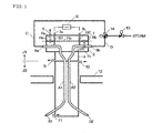
- the constitutional example of the sample treatment apparatus of the present invention (referred to hereinafter as “the present sample treatment apparatus") is illustrated in Fig. 1.
- the present sample treatment apparatus is a directly inserted sample treatment apparatus (referred to hereinafter as “the present probe") having a remarkable self-cleaning performance designed to measure a sulfur-rich environment in the sulfur recovery process by the Claus process.
- the present probe having self-cleaning performance described here can be applied similarly to a similar process where condensing components highly causing interference influence are present.
- the present probe can achieve the similar function and technical effect to the above not only by directly inserting the probe into the process line, but also by introducing a separately collected sample into the present probe.
- Sample gases in the sulfur recovery process by the Claus process are considerably different in composition from one another, depending on the constitution of the process, but generally contain: H 2 S 0 to 2%, SO 2 0 to 2%, COS 0 to 5000 ppm, CS 2 0 to 5000 ppm, the other substances such as Sv, water, nitrogen oxides (NOx), ammonia (NH 3 ) etc.
- the present probe having self-cleaning performance is composed of a heating zone Z1 and a cooling zone Z2.
- the probe shown in the figure has 2 sample treatment systems, but the number and constitution of the sample treatment systems are not limited thereto.
- the heating zone Z1 is composed of two flange disks 1, 2 and one hollow cylinder 4.
- the first disk 1 constitutes a steam inlet 5 for introducing heating steam or heating air (referred to hereinafter as "steam") for heating the heating zone Z1, a flow path Fa for steam in the first disk, and a flow path Fb for heating the first disk 1 and second disk 2.
- the second disk 2 constitutes a flow path Fb and a flow path Fc for feeding steam to the hollow cylinder 4, simultaneously forms sample flow paths A1 and A2 for two aspirators (having blowback function), and has parts 8a and 8b for introducing a fluid for an aspirator.
- the hollow cylinder In the hollow cylinder, steam is introduced through the flow path Fc into the hollow part, and the sample flow paths A1 and A2 are heated by the steam.
- the steam introduced into the hollow cylinder is discharged from a steam outlet 9.
- the fluid for an aspirator can include compressed air and high-temperature (for example 100 to 200°C) steam. The aspirator function and blowback function will be described later.
- the cooling zone Z2 is positioned just below the heating Z1 and constituted such that a part of the sample flow paths A1 and A2 is accommodated in the hollow cylindrical tube, and a refrigerant is introduced from a refrigerant inlet 10 to the hollow part and discharged from a refrigerant outlet 11.
- a buffer zone is not required between the heating zone Z1 and cooling zone Z2. This is because occurrence of a rapid change in temperature between the heating zone Z1 and cooling zone Z2 is not problematic for the reason that in the constitution where the sample flow paths A1 and A2 are formed throughout both the heating zone 1 and cooling zone Z2, (1) the heat transfer coefficient of gas is so high that rapid transfer to the determined temperature can be accomplished and (2) in the cooling zone Z2, precipitates are formed at the sides of lower sample collection parts S1 and S2.
- Temperature regulation is also used as a means to select a substance removed from the sample.
- the refrigerant used can include compressed air, water or a hydrocarbon-based refrigerant.
- a large amount of a fluid for an aspirator is introduced from the parts 8a, 8b for introducing a fluid for an aspirator, into the joining area between the sample flow path B1, B2 as thin tubes (for example, tubes each having an inner diameter of 2 to 6 mm) and the sample flow paths A1, A2 as thick tubes (for example, tubes each having an inner diameter of 8 to 10 mm), whereby the probe functions as an aspirator to suction a sample from the sample flow path A1 or A2 and the sample flow path B1 or B2. Simultaneously, it functions as a blowback, and precipitates in the sample flow paths A1, A2 are removed and simultaneously discharged into the process line.
- the sample flow path A for introducing a fluid for an aspirator is selected by a controller (not shown in the figure) and switched in a predetermined cycle (for example, several minutes to several hours). Specifically, as illustrated in Fig. 1, high-temperature steam connected to the electromagnetic valve 13 is switched by the electromagnetic valve 14 to the flow path C or D.
- the flow path C is connected via the part 8c for introducing a fluid for an aspirator to the sample flow path A1
- the flow path D is connected via the part 8b for introducing a fluid for an aspirator to the sample flow path A2, so the sample flow paths A1, A2 can alternately function as an aspirator and function as a remover of precipitates in the sample.
- One function as an aspirator is to collect a sample for example by the following procedures:
- blowback function refers generally to a sample treatment function wherein in a flow path through which a sample flows, a large amount of a fluid is introduced in the direction opposite to a sample flow so as to remove the precipitates that are contained in a sample and growing further or adhering to an internal wall of the flow path. That is, in the state (4), sulfur adhering to the wall of the sample flow path A2 in a cooled state gradually grows, and thus it can be estimated:
- the heating zone Z1 steam is introduced via the steam inlet 5 in the first disk 1 into the present probe to pass through the flow path Fa, and introduced into the flow path Fb between the first disk 1 and the second disk 2.
- the outlets of the flow paths Fa and Fb are provided with O-ring seals Ra and Rb to prevent leakage.
- the first disk 1 and the second disk 2 are provided additionally with an O-ring therebetween (not shown in the figure).
- the steam having passed through the flow path Fb passes through the flow path Fc in the second disk 2, to flow into a hollow cylinder 4 provided therein with a sample flow path A and sample flow path B, and is then discharged from the present probe through a steam outlet 9.
- the cooling zone Z2 is further positioned just below the heating zone Z1. A buffer zone is not necessary between the heating zone Z1 and the cooling zone Z2.
- the present measuring apparatus provided with the present sample treatment apparatus (the present probe), as a constitutional example is shown the present probe arranged by connecting it to a detection system 6 as a separate element shown in the broken line in Fig. 1 through connecting parts 7a and 7b.
- the measuring apparatus is fundamentally constituted such that the sample flow paths B1 and B2 in the ⁇ constitutional example of the present sample treatment apparatus> are connected to the detector system 6 outside the similar function to that of the present probe.
- detection systems of various measurement principles adapted to measurement components or sample states including not only a detection system of ultraviolet absorption type described later but also a detection system of infrared absorption type, and a thermal conductivity detection system can be utilized. And also an ion electrode detection system and a specific conductivity detection system can be utilized in a solution.
- the sample can be collected and measured in the following procedures.
- the measuring apparatus functions in the same manner as in the present probe in the above-described ⁇ constitutional example of the present sample treatment apparatus>.
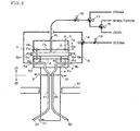
- the directly inserted probe having self-cleaning performance in the present measuring apparatus consists of a heating zone Z1 and a cooling zone Z2, and the heating zone Z1 is composed of three flange disks and one hollow cylinder 4.
- the second disk 2, the hollow cylinder 4 and the cooling zone Z2 have the same structures and functions as described above.
- the first disk 1 has both a steam inlet 5 for introduction of steam for heating the heating zone 1 and an inlet 15 for introducing a check gas, zero gas, span gas and/or cleaning gas fed to the sample cell part 6.
- the third disk 3 is provided with the sample cell part 6.
- Arranging ends 6c and 6d for optical fiber cables 6a and 6b for measuring the process sample by ultraviolet absorption spectrometry are provided in both connecting ends of the sample cell part 6. Steam is supplied into the flow path Fb between the first disk 1 and the third disk 3, and the flow path Fd between the third disk 3 and the second disk 2, and by its heat, the heating zone Z1 can be formed to prevent condensation of the process sample.
- the measurement operation of the present measuring apparatus is fundamentally the same as the measurement apparatus according to the first constitutional example, but is different in some aspects arising from integration of the 3 disks with one another, in addition to formation of the sample cell part 6 in a flow path for communicating the sample flow paths A1 and A2 with each other.
- the different aspects are mainly described.
- the flow paths in two sample treatment systems are switched mutually, whereby the process sample is collected near to the process line and can be measured rapidly, and at the same time the sample treatment system can be cleaned by blowback.
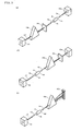
- an optical system consisting of an ultraviolet light source part 61, a sample cell part 6, an ultraviolet light detector 63a or 63b and spectrometric elements 64a to 64c is formed wherein the amount of the ultraviolet light (corresponding to UV in the figure) absorbed by a measurement component in a sample introduced into the sample cell part 6 is detected with the ultraviolet light detector 63a or 63b, whereby the concentration of the measurement component in the sample can be measured.
- the spectrometric element can include an element wherein a monochromator 64a and slit 64b are combined as shown in Figs. 3 (A) and (B), whereby the amount of absorbed ultraviolet light in a narrow range is detected by an ultraviolet light detector 63a.
- the element shown in Fig. 3 (C) uses a polychromator 64c as spectrometric element to enable detection of the amount of absorbed ultraviolet light in a plurality of wavelength ranges by an ultraviolet light detector 63b consisting of a plurality of detection elements.
- the ultraviolet light source 61 As the ultraviolet light source 61, a low-pressure mercury lamp, a heavy hydrogen lamp, a xenon lamp etc. are generally used. From the practical viewpoint or in respect of costs, a low-pressure mercury lamp is often used. It also enables to use the so-called "modulation" means wherein the ultraviolet light source 61 is repeatedly turned on/off in a predetermined cycle.
- the sample cell part 6 can use quartz, glass or a metallic tube of stainless steel or aluminum. As shown in Fig. 3 (A) to (C), the shape is generally in a cylindrical form of about 1 to 500 mm with a cell length determined so as to be adjusted to the concentration of a measurement component, and a substantial length optical path cell utilizing multiple reflection provided therein with a mirror or the like is also utilized frequently. A square pillar cell made of quartz can also be used.
- the ultraviolet light is utilized in the range of wavelengths at which other coexistent components show less absorption.
- wavelengths in the vicinity of 210 to 220 nm are used for measurement of H2S, and wavelengths in the vicinity of 280 to 300 nm are used for SO 2 .
- An optical filter called a band pass filter (BPF) allowing lights in the above wavelength range to permeate selectively therethrough is sometimes arranged between the ultraviolet light source part 61 and ultraviolet light detector 63a or 63b, but in the present example, the wavelength is selected depending on a combination of the monochromator 64a and slit 64b as shown in Fig. 3 (A) and Fig.
- the amount of light absorbed in the selected wavelength can be detected by the ultraviolet light detector 63a, or as shown in Fig. 3 (C), the light is spectral-diffracted into its spectral component by the polychromator 64c, and the amount of the absorbed light thus spectral-diffracted is monitored in the whole wavelength by an array ultraviolet light detector 63b.
- a check gas, zero gas, span gas or cleaning gas is introduced from an inlet 15 into the first disk 1 via an electromagnetic valve 16 for switching between a zero gas (calibration gas) and a span gas (or a check gas), an electromagnetic valve 17 for switching between a calibration gas and a cleaning gas (steam etc.), and an electromagnetic valve 18 for shutting.
- the introduction and switching of these gases are controlled by the upstream electromagnetic valves 16 to 18.
- the electromagnetic valve 18 can be actuated to introduce a calibration gas into the sample cell part 6 to calibrate the ultraviolet light absorption-type analyzer.
- steam is introduced via the electromagnetic valves 17 and 18 to pass through the first disk 1, and is introduced into the sample cell part 6 in the third disk 3.
- the steam introduced into the sample cell part 6 dissolves precipitates in the sample cell part 6, and is discharged together with the fluid for an aspirator, from the sample flow path A1 or A2 via the sample flow path B1 or B2 connected to the sample cell part 6.
- the flow rate of the fluid for an aspirator passing through the sample flow path A1 or A2 is very high, and the flow rate of the sample is low, and thus the cleaning effect in the sample flow path A1 or A2 can be sufficiently secured.
- a controller 20 for the control of the electromagnetic valves 13 and 14 for switching introduction of steam as a fluid for an aspirator, for the control of the electromagnetic valves 16 to 18 for switching introduction of a calibration gas (including a check gas) and a cleaning gas into the sample cell part 6, and for processing the inputting and outputting of the optical fibers 6a and 6b connected to the sample cell part 6.
- a controller 20 for the control of the electromagnetic valves 13 and 14 for switching introduction of steam as a fluid for an aspirator, for the control of the electromagnetic valves 16 to 18 for switching introduction of a calibration gas (including a check gas) and a cleaning gas into the sample cell part 6, and for processing the inputting and outputting of the optical fibers 6a and 6b connected to the sample cell part 6.
- the controller 20 has not only various kinds of control function of the present probe, but also has functions necessary for maintaining the performance of the measuring apparatus, with respect to the elements in the detection system, for example, the ultraviolet light source and ultraviolet light detector, and the amplifier and converter of output of the ultraviolet light detector, and simultaneously has a function of inputting and outputting signals to the outside or feeding a power source.
Landscapes
- Health & Medical Sciences (AREA)
- Life Sciences & Earth Sciences (AREA)
- Engineering & Computer Science (AREA)
- Biomedical Technology (AREA)
- Molecular Biology (AREA)
- Physics & Mathematics (AREA)
- Chemical & Material Sciences (AREA)
- Analytical Chemistry (AREA)
- Biochemistry (AREA)
- General Health & Medical Sciences (AREA)
- General Physics & Mathematics (AREA)
- Immunology (AREA)
- Pathology (AREA)
- Sampling And Sample Adjustment (AREA)
- Investigating Or Analysing Materials By Optical Means (AREA)
Applications Claiming Priority (1)
| Application Number | Priority Date | Filing Date | Title |
|---|---|---|---|
| US11/311,066 US7395725B2 (en) | 2005-12-19 | 2005-12-19 | Sample treatment apparatus and sample measurement apparatus providing it |
Publications (2)
| Publication Number | Publication Date |
|---|---|
| EP1798538A2 true EP1798538A2 (de) | 2007-06-20 |
| EP1798538A3 EP1798538A3 (de) | 2007-12-19 |
Family
ID=37946731
Family Applications (1)
| Application Number | Title | Priority Date | Filing Date |
|---|---|---|---|
| EP06025610A Withdrawn EP1798538A3 (de) | 2005-12-19 | 2006-12-11 | Vorrichtung zur Probenbehandlung und Vorrichtung zur Messung |
Country Status (4)
| Country | Link |
|---|---|
| US (1) | US7395725B2 (de) |
| EP (1) | EP1798538A3 (de) |
| JP (1) | JP4614241B2 (de) |
| CN (1) | CN101046481B (de) |
Cited By (2)
| Publication number | Priority date | Publication date | Assignee | Title |
|---|---|---|---|---|
| EP1988380A3 (de) * | 2007-05-04 | 2010-06-23 | GEMÜ Gebrüder Müller Apparatebau GmbH & Co. KG | Probenahmevorrichtung |
| EP2016388A4 (de) * | 2006-04-20 | 2013-05-01 | Scantech Int Pty Ltd | Partikelbeobachtungsvorrichtung |
Families Citing this family (6)
| Publication number | Priority date | Publication date | Assignee | Title |
|---|---|---|---|---|
| JP4951564B2 (ja) * | 2008-03-25 | 2012-06-13 | 住友化学株式会社 | 再生硫黄回収装置 |
| JP4968207B2 (ja) * | 2008-07-31 | 2012-07-04 | 住友化学株式会社 | 硫化水素ガスの精製方法。 |
| US20100240135A1 (en) * | 2009-03-19 | 2010-09-23 | Seeger David M | System and method for sour gas well testing |
| CN102288745B (zh) * | 2011-07-01 | 2013-08-14 | 深圳市麦迪聪医疗电子有限公司 | 多通道生化分析仪的通道分配控制方法 |
| US10366594B2 (en) * | 2015-05-04 | 2019-07-30 | Mountain Optech, Inc. | Oil and gas production facility emissions sensing and alerting device, system and method |
| CN110579378B (zh) * | 2018-06-07 | 2024-06-21 | 北京航天益来电子科技有限公司 | 烟气可持续采样探杆 |
Family Cites Families (19)
| Publication number | Priority date | Publication date | Assignee | Title |
|---|---|---|---|---|
| US2814952A (en) * | 1955-11-30 | 1957-12-03 | Standard Oil Co | Gas sampling and temperature measuring device |
| JPS5014139B1 (de) * | 1969-08-29 | 1975-05-26 | ||
| US3748906A (en) * | 1970-10-15 | 1973-07-31 | Jones & Laughlin Steel Corp | Gas sampling apparatus |
| JPS57119239A (en) * | 1980-12-01 | 1982-07-24 | Du Pont | Photometric analysis method of and apparatus for concentration of hydrogen sulfide |
| EP0081637A1 (de) * | 1981-11-10 | 1983-06-22 | Krupp Polysius Ag | Entnahme- und Analysiervorrichtung für staubhaltige Gasproben |
| BE893366A (fr) | 1982-05-28 | 1982-09-16 | Centre Rech Metallurgique | Perfectionnements aux dispositifs de prelevement d'echantillons gazeux |
| GB8517549D0 (en) | 1985-07-11 | 1985-08-14 | Smidth & Co As F L | Gas monitoring equipment |
| DE3660941D1 (en) * | 1986-04-29 | 1988-11-17 | Voest Alpine Ind Anlagen | Method and apparatus for continuous hot gas sampling for analysis in a reactor |
| JPH06229889A (ja) * | 1993-02-01 | 1994-08-19 | Nikkiso Co Ltd | 粉体サンプリング装置 |
| NL9302081A (nl) | 1993-11-30 | 1995-06-16 | Gastec Nv | Werkwijze voor het verwijderen van elementaire zwavel uit een gasstroom. |
| SE503720C2 (sv) * | 1994-02-28 | 1996-08-12 | Sunds Defibrator Ind Ab | Sätt och anordning för kontinuerlig provtagning för analys av en materialblandning |
| US5473951A (en) * | 1994-06-23 | 1995-12-12 | Tomlin; Robert L. | Differential dilution sampling probe |
| JP3422577B2 (ja) * | 1994-10-22 | 2003-06-30 | 株式会社堀場製作所 | 多点サンプル測定装置 |
| US6200819B1 (en) * | 1995-09-29 | 2001-03-13 | Horiba Instruments, Inc. | Method and apparatus for providing diluent gas to exhaust emission analyzer |
| US5627328A (en) * | 1995-12-29 | 1997-05-06 | Gas Research Institute | Gas sampling system and method |
| JPH09218176A (ja) * | 1996-02-14 | 1997-08-19 | Chikyu Kankyo Sangyo Gijutsu Kenkyu Kiko | ガス分析装置 |
| JP3397977B2 (ja) * | 1996-05-23 | 2003-04-21 | 中国電力株式会社 | ガスサンプリング装置 |
| JP3617622B2 (ja) * | 2000-11-02 | 2005-02-09 | 株式会社タクマ | ガス分析装置 |
| JP2003232758A (ja) * | 2002-02-08 | 2003-08-22 | Mineral Seimitsu Kagaku Kk | 燃焼排ガスのso3濃度の測定方法及び測定装置並びにso3を含有する燃焼排ガス処理方法及び処理装置 |
-
2005
- 2005-12-19 US US11/311,066 patent/US7395725B2/en not_active Expired - Fee Related
-
2006
- 2006-12-11 EP EP06025610A patent/EP1798538A3/de not_active Withdrawn
- 2006-12-18 JP JP2006340254A patent/JP4614241B2/ja not_active Expired - Fee Related
- 2006-12-19 CN CN2006101675654A patent/CN101046481B/zh not_active Expired - Fee Related
Cited By (2)
| Publication number | Priority date | Publication date | Assignee | Title |
|---|---|---|---|---|
| EP2016388A4 (de) * | 2006-04-20 | 2013-05-01 | Scantech Int Pty Ltd | Partikelbeobachtungsvorrichtung |
| EP1988380A3 (de) * | 2007-05-04 | 2010-06-23 | GEMÜ Gebrüder Müller Apparatebau GmbH & Co. KG | Probenahmevorrichtung |
Also Published As
| Publication number | Publication date |
|---|---|
| EP1798538A3 (de) | 2007-12-19 |
| CN101046481A (zh) | 2007-10-03 |
| JP2007171183A (ja) | 2007-07-05 |
| US7395725B2 (en) | 2008-07-08 |
| JP4614241B2 (ja) | 2011-01-19 |
| CN101046481B (zh) | 2010-12-01 |
| US20070137316A1 (en) | 2007-06-21 |
Similar Documents
| Publication | Publication Date | Title |
|---|---|---|
| TW421843B (en) | Protection of semiconductor fabrication and similar sensitive processes | |
| US7395725B2 (en) | Sample treatment apparatus and sample measurement apparatus providing it | |
| US20080188002A1 (en) | Method and apparatus for removing selenium oxide in a sample, and method and apparatus for measuring mercury in coal combustion exhaust gas by using the same | |
| US8021617B2 (en) | Flue gas monitoring and dynamic spiking for sulfur trioxide/sulfuric acid | |
| KR101460874B1 (ko) | 암모니아 화합물 농도 계측 장치 및 암모니아 화합물 농도 계측 방법 | |
| EP1507140B1 (de) | Analyse-Verfahren und -Vorrichtung zur Messung von Konzentrationen von Schwefelverbindungen mittels ultravioletter Fluoreszenz | |
| JP2009058306A (ja) | 液体中の溶存無機物質濃度測定方法及び測定装置、並びに、当該溶存無機物質濃度測定装置を備えたエッチング液再生システム | |
| KR101760259B1 (ko) | 추출 암모니아 연속 모니터링 시스템 | |
| US20240359153A1 (en) | Method and system for generating interference spectra for low detection limits using reactor | |
| EP4542194A1 (de) | System zur kontinuierlichen gasanalyse und verfahren zur kontinuierlichen gasanalyse | |
| JP2011080768A (ja) | ガス分析装置 | |
| JP5325091B2 (ja) | ガス成分計測装置及びガス成分分析方法 | |
| JP2007271460A (ja) | 石炭燃焼排気ガス中の水銀測定方法および測定装置 | |
| JP2004138467A (ja) | 紫外線吸収式測定装置および測定試料の処理方法 | |
| JP4899259B2 (ja) | So3,nh3同時連続濃度計 | |
| JP4188096B2 (ja) | 測定装置 | |
| JP4109578B2 (ja) | 化学発光式ガス分析方法および装置 | |
| CN2914071Y (zh) | 一种烟气排放连续监测系统 | |
| JP4674417B2 (ja) | So3濃度計 | |
| JP7521684B2 (ja) | ガス分析装置 | |
| JP2003004634A (ja) | 灰中未燃分計測システム | |
| JP2004226098A (ja) | 流体変調式測定装置 | |
| JP5423662B2 (ja) | 水質分析計 | |
| JP2001349812A (ja) | ガス分析計の干渉影響の低減方法 | |
| JPH10239302A (ja) | コークス炉ガス中のアンモニア濃度自動測定方法 |
Legal Events
| Date | Code | Title | Description |
|---|---|---|---|
| PUAI | Public reference made under article 153(3) epc to a published international application that has entered the european phase |
Free format text: ORIGINAL CODE: 0009012 |
|
| AK | Designated contracting states |
Kind code of ref document: A2 Designated state(s): AT BE BG CH CY CZ DE DK EE ES FI FR GB GR HU IE IS IT LI LT LU LV MC NL PL PT RO SE SI SK TR |
|
| AX | Request for extension of the european patent |
Extension state: AL BA HR MK YU |
|
| PUAL | Search report despatched |
Free format text: ORIGINAL CODE: 0009013 |
|
| AK | Designated contracting states |
Kind code of ref document: A3 Designated state(s): AT BE BG CH CY CZ DE DK EE ES FI FR GB GR HU IE IS IT LI LT LU LV MC NL PL PT RO SE SI SK TR |
|
| AX | Request for extension of the european patent |
Extension state: AL BA HR MK YU |
|
| 17P | Request for examination filed |
Effective date: 20080602 |
|
| 17Q | First examination report despatched |
Effective date: 20080707 |
|
| AKX | Designation fees paid |
Designated state(s): DE FR |
|
| GRAP | Despatch of communication of intention to grant a patent |
Free format text: ORIGINAL CODE: EPIDOSNIGR1 |
|
| STAA | Information on the status of an ep patent application or granted ep patent |
Free format text: STATUS: THE APPLICATION IS DEEMED TO BE WITHDRAWN |
|
| 18D | Application deemed to be withdrawn |
Effective date: 20101215 |