EP1798547A1 - Capteur de vapeur d'eau colorimétrique - Google Patents
Capteur de vapeur d'eau colorimétrique Download PDFInfo
- Publication number
- EP1798547A1 EP1798547A1 EP07101473A EP07101473A EP1798547A1 EP 1798547 A1 EP1798547 A1 EP 1798547A1 EP 07101473 A EP07101473 A EP 07101473A EP 07101473 A EP07101473 A EP 07101473A EP 1798547 A1 EP1798547 A1 EP 1798547A1
- Authority
- EP
- European Patent Office
- Prior art keywords
- cathode
- anode
- separator
- sensor
- longitudinal
- Prior art date
- Legal status (The legal status is an assumption and is not a legal conclusion. Google has not performed a legal analysis and makes no representation as to the accuracy of the status listed.)
- Granted
Links
Images


Classifications
-
- G—PHYSICS
- G01—MEASURING; TESTING
- G01N—INVESTIGATING OR ANALYSING MATERIALS BY DETERMINING THEIR CHEMICAL OR PHYSICAL PROPERTIES
- G01N27/00—Investigating or analysing materials by the use of electric, electrochemical, or magnetic means
- G01N27/26—Investigating or analysing materials by the use of electric, electrochemical, or magnetic means by investigating electrochemical variables; by using electrolysis or electrophoresis
- G01N27/416—Systems
- G01N27/42—Measuring deposition or liberation of materials from an electrolyte; Coulometry, i.e. measuring coulomb-equivalent of material in an electrolyte
- G01N27/423—Coulometry
Definitions
- the invention relates to water vapor sensors and more specifically to sensors for measuring trace amounts of water vapor.
- electrochemical sensors i.e., sensors employing an electrolytic cell with an anode, cathode and electrolyte
- electrochemical sensors i.e., sensors employing an electrolytic cell with an anode, cathode and electrolyte
- the invention is a sensor for detecting water vapor in a gaseous sample.
- the sensor comprises (a) an anode, (b) a cathode, (c) an electrolyte intermediate the anode and cathode, and (d) an inlet orifice through a central area of the anode or cathode through which the gaseous sample may be placed into contact with the electrolyte.
- the senor includes (a) an anode having an interior-facing major surface and an exterior-facing major surface, (b) a cathode having an interior-facing major surface and an exterior-facing major surface, (c) a gap between the interior-facing major surfaces of the anode and the cathode, (d) an electrolyte within the gap, (e) an inlet orifice through the anode or cathode through which a gaseous sample may flow into a central area of the gap, and (e) an outlet circumscribing the gap through which a gaseous sample introduced into the gap through the inlet orifice may exit the gap.
- a preferred embodiment of the sensor includes (a) a cylindrical housing defining a longitudinal lumen having first and second longitudinal ends, (b) a first endcap in longitudinal fixed relationship with the housing over the first longitudinal end of the lumen, (c) a second endcap in longitudinal fixed relationship with the housing over the second longitudinal end of the lumen, and (d) an arrangement retained within the lumen between the endcaps.
- the arrangement comprises a longitudinally aligned sequence of (i) a first support plate, (ii) a compressed compression spring, (iii) a longitudinally slidable second support plate, (iii) a longitudinally slidable detection assembly comprising a longitudinal sequence of either (A) an anode, a porous electrical-insulating separator, and an electrode with a centrally positioned inlet orifice, or (B) an electrode, a porous electrical-insulating separator, and an anode with a centrally positioned inlet orifice, and (iv) a sealing plate in sealed peripheral engagement with the housing and having a centrally positioned inlet orifice in sealed fluid engagement with the centrally positioned inlet orifice in the anode or cathode.
- Figure 1 is a cross-sectional side view of one embodiment of the invention.
- Figure 2 is an enlarged cross-sectional side view of the inlet end of the invention shown in FIG. 1.
- Figure 3 is a further enlarged cross-sectional side view of a portion of the detection assembly of the invention shown in FIG. 1.
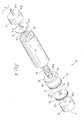
- Figure 4 is a longitudinally exploded perspective view of the invention shown in FIG. 1.
- central area means that area encompassing 50% of the area, of a given surface of an object positioned concentrically with the given surface and with a shape which matches the shape of the given surface area. Two examples are given below.
- the invention is a sensor 10 for detecting water vapor in a gaseous sample (not shown).
- the sensor 10 includes a detection assembly 40 retained in a fixed position within a housing 20 by a retention system (not collectively numbered).
- the housing 20 protectively surrounds the components of the sensor 10 - particularly the detection assembly 40 - and assists in retaining the components in a fixed, dimensionally stable position relative to one another while permitting controlled flow of a gaseous sample to be tested into contact with the detection assembly 40.
- the housing 20 may have any desired size and shape effective for achieving these functions, including the hollow cylinder or tube shape as shown in FIGs 1 and 4.
- the housing 20 may be constructed from any material possessing sufficient structural integrity, including specifically, but not exclusively, metals such as aluminum, copper, zinc and steel, plastics such as polyethylene, polypropylene, polyvinyl chloride and polyurethane, glass, wood, etc. Glass is generally preferred due to its highly inert and stable nature.
- a detection assembly 40 is retained within the lumen 29 of the housing 20.
- the detection assembly 40 includes an anode 50, a cathode 60, and an electrolyte (not shown) intermediate the anode 50 and cathode 60.
- the detection assembly 40 shown in FIGs 1-4 has the anode 50 positioned upstream from the cathode 60.
- the cathode 60 may be positioned upstream from the anode 50.
- the anode 50 may be constructed from any of the well known materials suitable for use as an anode in an electrolytic cell, provided the material can survive extended exposure to the electrolyte and the high concentration of atomic oxygen evolved at the interior surface 51 of the anode 50 during use.
- a preferred material - when the electrolyte is phosphoric acid - is indium oxide coated titanium.
- an inlet orifice 50a is provided through a central area (unnumbered) of the anode 50 for permitting passage of a gaseous sample through the anode 50 and into contact with the electrolyte at a. central location on the separator 70.
- this inlet orifice would be provided through a central area (unnumbered) of the cathode 60 rather than the anode 50.
- the electrolyte may be selected from any of the well-known electrolytes suitable for use in an electrolytic cell.
- Preferred electrolytes are the liquid electrolytes which are, applied as a liquid and then dried.
- the preferred liquid electrolyte - based predominantly upon its high affinity for the sorption of water vapor in a gaseous sample - for use in the sensor 10 is phosphoric acid applied as a 10% w/w aqueous solution.
- the electrolyte is positioned within the gap 79 between the anode 50 and the cathode 60. As a gaseous sample flows through the gap 79, the electrolyte "grabs” any water vapor in the gaseous sample. The "grabbed” water molecules are then promptly ionized into an O -2 anion and two H + cations by the electrical field generated by the anode 50 and the cathode 60 within the gap 79. The O -2 anion is attracted to the anode 50 while the H + cations are attracted to the cathode 60. A detectable electrical signal is generated when the O -2 anion is oxidized to O at the anode 50 and the H + cations are reduced to H at the cathode 60.
- the separator 70 needs to be constructed of a material which (i) is easily wetted by the electrolyte to achieve good conductivity through the insulator to the anode 50 and cathode 60, (ii) doesn't absorb water directly, (iii) can withstand the harsh electrical and chemical environment within the gap 79 (i. e. , extended exposure to phosphoric acid, O -2 , O, H + and H and the constant presence of an electrical potential) without degradation, and will not contaminate the gaseous sample.
- a material which (i) is easily wetted by the electrolyte to achieve good conductivity through the insulator to the anode 50 and cathode 60, (ii) doesn't absorb water directly, (iii) can withstand the harsh electrical and chemical environment within the gap 79 (i. e. , extended exposure to phosphoric acid, O -2 , O, H + and H and the constant presence of an electrical potential) without degradation, and will not contaminate the gaseous sample
- the separator 70 should have a thickness of about 0.2 mm to about 1 mm, preferably 0.2 mm to about 0.8 mm, as an appropriate compromise between a faster response provided with a thinner separator 70 and a longer useful life-span provided by a thicker separator 70 as a result of the increased amount of electrolyte carried by the separator 70.
- porous ceramics particularly woven ceramics such as tricot knit zirconium oxide and tricot knot hafnium oxide with modest preference for hafnium oxide due to the presence of yttrium as a stabilizer in zirconium oxide which tend to react with phosphoric acid over time.
- the electrolyte is preferably surface coated within the pores (not shown) of the separator 70. This provides a tortuous path of travel for the gaseous sample and a large surface area for retention of electrolyte.
- the detection assembly 40 may be conveniently held in place within the lumen 29 of the housing 20 by a retention system (not collectively numbered).
- the retention system includes (i) a first endcap 31 attached to the housing 20 over the first longitudinal end 21 of the housing 20, (ii) a second endcap 32 attached to the housing 20 over the second longitudinal end 22 of the housing 20, and (iii) a longitudinally aligned sequence of (A) a first support plate 81, (B) a. compressed compression spring 80, (C) a second support plate 82, and (D) a sealing plate 90.
- an outwardly directed longitudinal biasing force is provided by a compressed compression spring 80 concentrically positioned about the longitudinal axis 29x of the lumen 29.
- the spring 80 is held in position between a first support plate 81 abutting the first endcap 31 and a second support plate 82.
- the second support plate 82 is configured and arranged so that the plate 82 will longitudinally slide within the lumen 29 and thereby exert the outwardly directed longitudinal biasing force of the spring 80 onto those components positioned between the second support plate 82 and the second endcap 32.
- the first support plate 81 may be integrally formed with the first endcap 31.
- the spring 80 preferably exerts an outwardly directed force of between about 5 to about 20 psi.
- a force of less than about 5 psi does not provide sufficient force to ensure dimensional stability of the detection assembly 40 while a force of greater than about 20 psi may crush the separator 70.
- the first 81 and second 82 support plates each have a centrally positioned, longitudinally extending post 81p and 82p, respectively, for engaging and retaining the ends (unnumbered) of the spring 80.
- the first 81 and second 82 support plates may be constructed from any material possessing sufficient structural integrity, including specifically, but not exclusively, metals such as aluminum, copper, zinc and steel, plastics such as polyethylene, polypropylene, polyvinyl chloride and polyurethane, glass, wood, etc. Metals, such as steel, are generally preferred based upon the high structural integrity, low cost and generally inert nature of most metals.
- the sealing plate 90 may be constructed from any material possessing sufficient structural integrity, including specifically, but not exclusively, metals such as aluminum, copper, zinc and steel, plastics such as polyethylene, polypropylene, polyvinyl chloride and polyurethane, glass, wood, etc. Metals, such as stainless steel, are generally preferred based upon the high structural integrity, low cost and generally inert nature of most metals.
- an inlet tube 101 is integrally formed with the sealing plate 90 to define inlet orifice 90a through the center of the sealing plate 90, and extends through a longitudinal inlet orifice 32a in the center (unnumbered) of the second endcap 32.
- An inner O-ring 91 sealing engages the sealing plate 90 and the anode 50 around the inlet orifice 90a through the center of the sealing plate 90. This arrangement permits delivery of a gaseous sample into the gap 79 winch is exposed only to the delivery tube 101 and the anode 50 prior to delivery within the gap 79.
- the delivery tube 101 may be constructed from any suitably inert which call from an effective seal with the inner O-ring 91 and will not contaminate a gaseous sample passing through the delivery tube 101.
- suitable materials known to those skilled the art may be used, with a preference for stainless steel based upon the highly inert nature of stainless steel.
- the periphery of both the cathode 60 and the second support plate 82 is offset from the housing 20 so as to provide a circumferential passageway 60 c around the periphery of the cathode 60 and a circumferential passageway 82c around the periphery of the second support plate 82.
- These circumferential passageways 60c and 82c permit a gaseous sample delivered into the gap 79 to flow radially through the separator 70 and - upon exiting the separator 70 at the outer periphery 73 of the separator 70 - to flow through the circumferential passageways 60c and 82c towards the first longitudinal end 21 of the housing 20.
- circumferential passageways 60c and 82c can be conveniently created by employing a cylindrical lumen 29 and a disk-shaped cathode 60 and second support plate 82, and then simply making the diameter of the cathode 60 and the second support plate 82 slightly smaller than the diameter of the lumen 29, When assembled, the undersized cathode 60 and second support plate 82 will only contact the housing 20 at a single point along the periphery of the cathode 60 and second support, plate 82, thereby creating a circumferential passageway 60c around the cathode 60 and a circumferential passageway 82c around the second support plate 82.
- circumferential passageways 60c and 82c can be created by providing at least three radially-extending projections (not shown) uniformly-spaced around the periphery of each of the cathode 60 and the second, support plate 82. These projections, such as a raised bump, a longitudinal linear tooth or a cylindrical post, contact the housing 20 and thereby space the periphery of the cathode 60 and the periphery of the, second support plate 82 a distance from -the housing 20 to create the circumferential passageways 60c and 82c, respectively.
- projections such as a raised bump, a longitudinal linear tooth or a cylindrical post
- an exhaust tube 102 extends through a longitudinal orifice 31a in the center (unnumbered) of the first endcap 31 and through an outlet orifice 81a in the center (unnumbered) of the first support plate 81.
- the proximal end 102p of the exhaust tube 102 can terminate anywhere from the first endcap 31 to the second support plate 82.
- the exhaust tube 102 may be constructed from any material regardless of its ability to form a seal and regardless of whether the material may contaminate the "spent" gaseous sample. While a wide variety of materials may be employed, it is generally most convenient to use the same material for both the inlet tube 101 and the exhaust tube 102.
- the anode 50 is connected to the positive half of a source of electricity (not shown) by an anode lead 121 which passes through longitudinally aligned orifices 90b and 32b in the sealing plate 90 in the second endcap 32 respectively.
- the cathode 60 is connected to the negative half of a source of electricity by a cathode lead 122 which passes through longitudinally aligned orifices 82b, 81b and 31b in the second support plate 82, the first support plate 81 and the first endcap 31 respectively .
- the sensor 10 is used by pumping a gaseous sample through the sensor 10 at a known flow rate.
- the flow rate should be maintained between a minimum of about 2 cm 3 /min and a maximum of about 60 - 120 cm 3 /min - depending upon the size and porosity of the separator 70.
- a flow rate of less than about 2 cm 3 /min is difficult to accurately control while a flow rate of greater than about 60-120 cm 3 /min can reduce efficiency of the sensor 10 by moving water vapor through the separator 70 with a velocity which limits the ability of the electrolyte to grab and hold onto the water vapor.
- a gaseous sample introduced into the inlet tube 101 flows sequentially (i) through the inlet tube 101 past the longitudinal inlet orifice 32a in the center of the second endcap 32 and the longitudinal inlet orifice 90a in the center of the sealing plate 90, (ii) through the inlet orifice 50a in the center of the anode 50, and (iii) into the gap 79 and the pores of the separator 70 where (A) direction of flow changes from an axial flow along the longitudinal axis x of the sensor 10 to a 360° radial flow r from the longitudinal axis x, and (B) the sample is exposed to the electrolyte and the electrical field generated by the anode 50 and the cathode 60.
- the spent sample i.e., the sample after removal of any ixlater-vapor by the detection assembly 40 then exits the sensor 10 by flowing (iv) out from the gap 79 through the outer periphery 73 of the separator 70, (v) through the circumferential passageway 60c in the cathode 60 and the circumferential passageway 82c in the second support plate 82, (vi) past the spring 80, and (vii) into the exhaust tube 102 for travel out of the sensor 10 through the longitudinal outlet orifice 81a in the center of the first support plate 81 and the longitudinal outlet orifice 31a in the center of the first endcap 31.
- the electrolyte coated onto the surface of the pores in the separator 70 "grab” any water vapor in the gaseous sample.
- the "grabbed” water molecules are then promptly ionized into an O -2 anion and two H + cations by the electrical field generated by the anode 50 and the cathode 60 within the gap 79.
- the O -2 anion is attracted to the anode 50 while the H + cations are attracted to the cathode 60.
- An electrical signal is generated when the O -2 anion is oxidized, to O at the anode 50 and the H + cations are reduced to H at the cathode 60.
- Current generated within the detector 40 is directly proportional to the water disassociated within the detector 40 and follows Faraday's Law. This electrical signal can be detected and measured by standard control systems well known to those of skill in the field.
Landscapes
- Chemical & Material Sciences (AREA)
- Life Sciences & Earth Sciences (AREA)
- Health & Medical Sciences (AREA)
- Biochemistry (AREA)
- General Physics & Mathematics (AREA)
- Electrochemistry (AREA)
- Physics & Mathematics (AREA)
- Analytical Chemistry (AREA)
- Molecular Biology (AREA)
- General Health & Medical Sciences (AREA)
- Chemical Kinetics & Catalysis (AREA)
- Immunology (AREA)
- Pathology (AREA)
- Sampling And Sample Adjustment (AREA)
- Drying Of Gases (AREA)
- Measuring Oxygen Concentration In Cells (AREA)
- Investigating Or Analysing Materials By Optical Means (AREA)
Applications Claiming Priority (2)
| Application Number | Priority Date | Filing Date | Title |
|---|---|---|---|
| US11/012,046 US7569128B2 (en) | 2004-12-14 | 2004-12-14 | Coulometric water vapor sensor |
| EP05025662A EP1672362B1 (fr) | 2004-12-14 | 2005-11-24 | Capteur de vapeur d'eau colorimétrique |
Related Parent Applications (1)
| Application Number | Title | Priority Date | Filing Date |
|---|---|---|---|
| EP05025662A Division EP1672362B1 (fr) | 2004-12-14 | 2005-11-24 | Capteur de vapeur d'eau colorimétrique |
Publications (2)
| Publication Number | Publication Date |
|---|---|
| EP1798547A1 true EP1798547A1 (fr) | 2007-06-20 |
| EP1798547B1 EP1798547B1 (fr) | 2008-03-19 |
Family
ID=35820867
Family Applications (2)
| Application Number | Title | Priority Date | Filing Date |
|---|---|---|---|
| EP07101473A Expired - Lifetime EP1798547B1 (fr) | 2004-12-14 | 2005-11-24 | Capteur de vapeur d'eau colorimétrique |
| EP05025662A Expired - Lifetime EP1672362B1 (fr) | 2004-12-14 | 2005-11-24 | Capteur de vapeur d'eau colorimétrique |
Family Applications After (1)
| Application Number | Title | Priority Date | Filing Date |
|---|---|---|---|
| EP05025662A Expired - Lifetime EP1672362B1 (fr) | 2004-12-14 | 2005-11-24 | Capteur de vapeur d'eau colorimétrique |
Country Status (5)
| Country | Link |
|---|---|
| US (1) | US7569128B2 (fr) |
| EP (2) | EP1798547B1 (fr) |
| JP (1) | JP4529140B2 (fr) |
| AT (2) | ATE377189T1 (fr) |
| DE (2) | DE602005003092T2 (fr) |
Families Citing this family (6)
| Publication number | Priority date | Publication date | Assignee | Title |
|---|---|---|---|---|
| JP5120966B2 (ja) * | 2009-12-21 | 2013-01-16 | 独立行政法人産業技術総合研究所 | 極微量水分計測素子および該計測素子を用いた防湿封止性能評価方法 |
| US8388742B2 (en) * | 2010-01-13 | 2013-03-05 | E I Du Pont De Nemours And Company | Apparatus to measure permeation of a gas through a membrane |
| US9080994B2 (en) * | 2012-10-11 | 2015-07-14 | Mocon, Inc. | Analyte sensor with spent gas flushed endcaps |
| US10126288B2 (en) * | 2016-07-11 | 2018-11-13 | Quipip, Llc | Sensor device, and systems and methods for obtaining measurements of selected characteristics of a concrete mixture |
| US11815504B2 (en) | 2016-07-11 | 2023-11-14 | Quipip, Llc | Sensor device, and systems and methods for obtaining measurements of selected characteristics of a concrete mixture |
| CN109884152B (zh) * | 2019-03-25 | 2022-02-08 | 广州西唐传感科技有限公司 | 基于电解水的检测装置、测试系统及测试方法 |
Citations (5)
| Publication number | Priority date | Publication date | Assignee | Title |
|---|---|---|---|---|
| US3081250A (en) * | 1958-02-24 | 1963-03-12 | Cons Electrodynamics Corp | Electrode structure |
| US3337441A (en) * | 1963-08-19 | 1967-08-22 | Atomic Energy Authority Uk | Phosphoric acid-glycerine electrolyte for hygroscopic cell |
| GB2008772A (en) * | 1977-11-29 | 1979-06-06 | Zlehit Pri Ban | Determination of the Partial Pressure of Water Vapour in a Mixture of Gases |
| US4800000A (en) * | 1987-06-03 | 1989-01-24 | Manufacturers Engineering Equipment Corp. | Low level moisture measurement system and method |
| EP0326421A2 (fr) * | 1988-01-29 | 1989-08-02 | Mitsui Engineering and Shipbuilding Co, Ltd. | Méthode d'analyse électrochimique |
Family Cites Families (19)
| Publication number | Priority date | Publication date | Assignee | Title |
|---|---|---|---|---|
| US2830945A (en) | 1955-05-03 | 1958-04-15 | Du Pont | Apparatus for water determination |
| US3061250A (en) * | 1960-07-05 | 1962-10-30 | Outboard Marine Corp | Transom mounting for an outboard motor |
| US3909386A (en) * | 1970-11-10 | 1975-09-30 | Energetics Science | Gas detector unit |
| DE2621677A1 (de) * | 1976-05-15 | 1977-11-24 | Bayer Ag | Verfahren zur ueberpruefung von gasanalysengeraeten |
| US4083765A (en) * | 1976-12-21 | 1978-04-11 | The United States Of America As Represented By The Administrator Of The National Aeronautics And Space Administration | Polymeric electrolytic hygrometer |
| US4167457A (en) * | 1978-05-05 | 1979-09-11 | Giner, Inc. | Passive electrolytic separator |
| US4276146A (en) * | 1978-08-07 | 1981-06-30 | General Electric Company | Cell having catalytic electrodes bonded to a membrane separator |
| US4514278A (en) | 1983-01-14 | 1985-04-30 | The United States Of America As Represented By The Administrator Of The National Aeronautics And Space Administration | Trace water sensor |
| GB8313846D0 (en) * | 1983-05-19 | 1983-06-22 | City Tech | Gas sensor |
| JPH0640092B2 (ja) * | 1983-08-09 | 1994-05-25 | 工業技術院長 | 湿度測定方法 |
| JPS6128856A (ja) * | 1984-07-19 | 1986-02-08 | Japan Storage Battery Co Ltd | 湿度センサ− |
| JPS626152A (ja) * | 1985-07-03 | 1987-01-13 | Yokogawa Electric Corp | イオン導電性固体電解質を用いた分析装置 |
| US4842709A (en) | 1987-12-07 | 1989-06-27 | Eg&G Chandler Engineering | Electrolytic cell and process for the operation of electrolytic cells, for moisture analyzers |
| GB8801669D0 (en) | 1988-01-26 | 1988-02-24 | Ici Plc | Isomerisation process |
| JPH01213564A (ja) | 1988-02-23 | 1989-08-28 | Japan Gore Tex Inc | 感湿素子およびその製造法 |
| US5164053A (en) | 1990-04-23 | 1992-11-17 | Teledyne Industries, Inc. | Electrochemical gas sensor and method of using same |
| US5199295A (en) | 1991-01-22 | 1993-04-06 | Meeco, Inc. | Feedback controlled gas mixture generator especially for an hygrometer reaction check |
| US5322602A (en) | 1993-01-28 | 1994-06-21 | Teledyne Industries, Inc. | Gas sensors |
| DE19726453C2 (de) * | 1997-06-21 | 2000-08-10 | Draegerwerk Ag | Elektrochemischer Sauerstoffsensor |
-
2004
- 2004-12-14 US US11/012,046 patent/US7569128B2/en active Active
-
2005
- 2005-11-24 DE DE602005003092T patent/DE602005003092T2/de not_active Expired - Lifetime
- 2005-11-24 AT AT05025662T patent/ATE377189T1/de not_active IP Right Cessation
- 2005-11-24 AT AT07101473T patent/ATE389877T1/de not_active IP Right Cessation
- 2005-11-24 EP EP07101473A patent/EP1798547B1/fr not_active Expired - Lifetime
- 2005-11-24 DE DE602005005504T patent/DE602005005504T2/de not_active Expired - Lifetime
- 2005-11-24 EP EP05025662A patent/EP1672362B1/fr not_active Expired - Lifetime
- 2005-12-14 JP JP2005360734A patent/JP4529140B2/ja not_active Expired - Lifetime
Patent Citations (5)
| Publication number | Priority date | Publication date | Assignee | Title |
|---|---|---|---|---|
| US3081250A (en) * | 1958-02-24 | 1963-03-12 | Cons Electrodynamics Corp | Electrode structure |
| US3337441A (en) * | 1963-08-19 | 1967-08-22 | Atomic Energy Authority Uk | Phosphoric acid-glycerine electrolyte for hygroscopic cell |
| GB2008772A (en) * | 1977-11-29 | 1979-06-06 | Zlehit Pri Ban | Determination of the Partial Pressure of Water Vapour in a Mixture of Gases |
| US4800000A (en) * | 1987-06-03 | 1989-01-24 | Manufacturers Engineering Equipment Corp. | Low level moisture measurement system and method |
| EP0326421A2 (fr) * | 1988-01-29 | 1989-08-02 | Mitsui Engineering and Shipbuilding Co, Ltd. | Méthode d'analyse électrochimique |
Also Published As
| Publication number | Publication date |
|---|---|
| DE602005005504D1 (de) | 2008-04-30 |
| DE602005005504T2 (de) | 2008-07-24 |
| ATE389877T1 (de) | 2008-04-15 |
| EP1672362B1 (fr) | 2007-10-31 |
| JP4529140B2 (ja) | 2010-08-25 |
| EP1798547B1 (fr) | 2008-03-19 |
| JP2006171000A (ja) | 2006-06-29 |
| ATE377189T1 (de) | 2007-11-15 |
| EP1672362A1 (fr) | 2006-06-21 |
| DE602005003092T2 (de) | 2008-08-14 |
| US7569128B2 (en) | 2009-08-04 |
| DE602005003092D1 (de) | 2007-12-13 |
| US20060124457A1 (en) | 2006-06-15 |
Similar Documents
| Publication | Publication Date | Title |
|---|---|---|
| EP0124818B1 (fr) | Méthode électroanalytique et capteur pour la détermination de l'hydrogène | |
| US4377446A (en) | Carbon dioxide measurement | |
| EP3175230B1 (fr) | Détecteur de gaz avec filtre segmenté | |
| SE461615B (sv) | Elektrokemisk cell och foerfarande foer kvantitativ detektering av giftig gas | |
| AU2013369643B2 (en) | An electrochemical sensor for sensing nitrous oxide | |
| EP2534727A1 (fr) | Cellule de détection électrochimique pour un système de chromatographie en phase liquide | |
| JP6163202B2 (ja) | 水性流の全有機含有量を測定する方法及び装置 | |
| EP1798547B1 (fr) | Capteur de vapeur d'eau colorimétrique | |
| WO2015060328A1 (fr) | Capteur de gaz électrolytique potentiostatique | |
| US3713994A (en) | Electrochemical air pollution monitoring device and method of use thereof | |
| JPS61288149A (ja) | アンペロメトリツク測定法及び該方法のためのセル | |
| JP3881540B2 (ja) | 定電位電解式ガスセンサおよびガス検知装置 | |
| JP4671565B2 (ja) | 隔膜型電極 | |
| JP6209327B2 (ja) | 定電位電解式ガスセンサ | |
| JP3856775B2 (ja) | ガスセンサ | |
| EP0230289A2 (fr) | Détermination électrochimique du formaldéhyde | |
| GB2073430A (en) | Gas detection device | |
| US20080116083A1 (en) | Electrochemical gas sensor with at least one punctiform measuring electrode | |
| Xie et al. | A Solid‐State Ozone Sensor Based on Solid Polymer Electrolyte | |
| Nei | Some milestones in the 50-year history of electrochemical oxygen sensor development | |
| JP2954174B1 (ja) | 定電位電解式ガスセンサ | |
| US20070227908A1 (en) | Electrochemical cell sensor | |
| KR19990014660A (ko) | 고체 전해질을 이용한 용존산소 측정장치 | |
| JP6330213B2 (ja) | 定電位電解式酸素ガスセンサ | |
| US6391174B1 (en) | Ion exchange membrane for dissolved gas sensor |
Legal Events
| Date | Code | Title | Description |
|---|---|---|---|
| PUAI | Public reference made under article 153(3) epc to a published international application that has entered the european phase |
Free format text: ORIGINAL CODE: 0009012 |
|
| AC | Divisional application: reference to earlier application |
Ref document number: 1672362 Country of ref document: EP Kind code of ref document: P |
|
| AK | Designated contracting states |
Kind code of ref document: A1 Designated state(s): AT BE BG CH CY CZ DE DK EE ES FI FR GB GR HU IE IS IT LI LT LU LV MC NL PL PT RO SE SI SK TR |
|
| AX | Request for extension of the european patent |
Extension state: AL BA HR MK YU |
|
| 17P | Request for examination filed |
Effective date: 20070730 |
|
| GRAP | Despatch of communication of intention to grant a patent |
Free format text: ORIGINAL CODE: EPIDOSNIGR1 |
|
| GRAS | Grant fee paid |
Free format text: ORIGINAL CODE: EPIDOSNIGR3 |
|
| GRAA | (expected) grant |
Free format text: ORIGINAL CODE: 0009210 |
|
| AKX | Designation fees paid |
Designated state(s): AT BE BG CH CY CZ DE DK EE ES FI FR GB GR HU IE IS IT LI LT LU LV MC NL PL PT RO SE SI SK TR |
|
| AC | Divisional application: reference to earlier application |
Ref document number: 1672362 Country of ref document: EP Kind code of ref document: P |
|
| AK | Designated contracting states |
Kind code of ref document: B1 Designated state(s): AT BE BG CH CY CZ DE DK EE ES FI FR GB GR HU IE IS IT LI LT LU LV MC NL PL PT RO SE SI SK TR |
|
| REG | Reference to a national code |
Ref country code: GB Ref legal event code: FG4D |
|
| REG | Reference to a national code |
Ref country code: CH Ref legal event code: EP |
|
| REF | Corresponds to: |
Ref document number: 602005005504 Country of ref document: DE Date of ref document: 20080430 Kind code of ref document: P |
|
| REG | Reference to a national code |
Ref country code: IE Ref legal event code: FG4D |
|
| PG25 | Lapsed in a contracting state [announced via postgrant information from national office to epo] |
Ref country code: LT Free format text: LAPSE BECAUSE OF FAILURE TO SUBMIT A TRANSLATION OF THE DESCRIPTION OR TO PAY THE FEE WITHIN THE PRESCRIBED TIME-LIMIT Effective date: 20080319 Ref country code: FI Free format text: LAPSE BECAUSE OF FAILURE TO SUBMIT A TRANSLATION OF THE DESCRIPTION OR TO PAY THE FEE WITHIN THE PRESCRIBED TIME-LIMIT Effective date: 20080319 |
|
| PG25 | Lapsed in a contracting state [announced via postgrant information from national office to epo] |
Ref country code: AT Free format text: LAPSE BECAUSE OF FAILURE TO SUBMIT A TRANSLATION OF THE DESCRIPTION OR TO PAY THE FEE WITHIN THE PRESCRIBED TIME-LIMIT Effective date: 20080319 |
|
| NLV1 | Nl: lapsed or annulled due to failure to fulfill the requirements of art. 29p and 29m of the patents act | ||
| ET | Fr: translation filed | ||
| PG25 | Lapsed in a contracting state [announced via postgrant information from national office to epo] |
Ref country code: LV Free format text: LAPSE BECAUSE OF FAILURE TO SUBMIT A TRANSLATION OF THE DESCRIPTION OR TO PAY THE FEE WITHIN THE PRESCRIBED TIME-LIMIT Effective date: 20080319 Ref country code: SI Free format text: LAPSE BECAUSE OF FAILURE TO SUBMIT A TRANSLATION OF THE DESCRIPTION OR TO PAY THE FEE WITHIN THE PRESCRIBED TIME-LIMIT Effective date: 20080319 Ref country code: PL Free format text: LAPSE BECAUSE OF FAILURE TO SUBMIT A TRANSLATION OF THE DESCRIPTION OR TO PAY THE FEE WITHIN THE PRESCRIBED TIME-LIMIT Effective date: 20080319 Ref country code: BE Free format text: LAPSE BECAUSE OF FAILURE TO SUBMIT A TRANSLATION OF THE DESCRIPTION OR TO PAY THE FEE WITHIN THE PRESCRIBED TIME-LIMIT Effective date: 20080319 |
|
| PG25 | Lapsed in a contracting state [announced via postgrant information from national office to epo] |
Ref country code: CZ Free format text: LAPSE BECAUSE OF FAILURE TO SUBMIT A TRANSLATION OF THE DESCRIPTION OR TO PAY THE FEE WITHIN THE PRESCRIBED TIME-LIMIT Effective date: 20080319 Ref country code: ES Free format text: LAPSE BECAUSE OF FAILURE TO SUBMIT A TRANSLATION OF THE DESCRIPTION OR TO PAY THE FEE WITHIN THE PRESCRIBED TIME-LIMIT Effective date: 20080630 Ref country code: SK Free format text: LAPSE BECAUSE OF FAILURE TO SUBMIT A TRANSLATION OF THE DESCRIPTION OR TO PAY THE FEE WITHIN THE PRESCRIBED TIME-LIMIT Effective date: 20080319 Ref country code: PT Free format text: LAPSE BECAUSE OF FAILURE TO SUBMIT A TRANSLATION OF THE DESCRIPTION OR TO PAY THE FEE WITHIN THE PRESCRIBED TIME-LIMIT Effective date: 20080827 Ref country code: SE Free format text: LAPSE BECAUSE OF FAILURE TO SUBMIT A TRANSLATION OF THE DESCRIPTION OR TO PAY THE FEE WITHIN THE PRESCRIBED TIME-LIMIT Effective date: 20080619 |
|
| PG25 | Lapsed in a contracting state [announced via postgrant information from national office to epo] |
Ref country code: NL Free format text: LAPSE BECAUSE OF FAILURE TO SUBMIT A TRANSLATION OF THE DESCRIPTION OR TO PAY THE FEE WITHIN THE PRESCRIBED TIME-LIMIT Effective date: 20080319 Ref country code: RO Free format text: LAPSE BECAUSE OF FAILURE TO SUBMIT A TRANSLATION OF THE DESCRIPTION OR TO PAY THE FEE WITHIN THE PRESCRIBED TIME-LIMIT Effective date: 20080319 |
|
| PG25 | Lapsed in a contracting state [announced via postgrant information from national office to epo] |
Ref country code: IS Free format text: LAPSE BECAUSE OF FAILURE TO SUBMIT A TRANSLATION OF THE DESCRIPTION OR TO PAY THE FEE WITHIN THE PRESCRIBED TIME-LIMIT Effective date: 20080719 |
|
| PLBE | No opposition filed within time limit |
Free format text: ORIGINAL CODE: 0009261 |
|
| STAA | Information on the status of an ep patent application or granted ep patent |
Free format text: STATUS: NO OPPOSITION FILED WITHIN TIME LIMIT |
|
| PG25 | Lapsed in a contracting state [announced via postgrant information from national office to epo] |
Ref country code: DK Free format text: LAPSE BECAUSE OF FAILURE TO SUBMIT A TRANSLATION OF THE DESCRIPTION OR TO PAY THE FEE WITHIN THE PRESCRIBED TIME-LIMIT Effective date: 20080319 |
|
| 26N | No opposition filed |
Effective date: 20081222 |
|
| PG25 | Lapsed in a contracting state [announced via postgrant information from national office to epo] |
Ref country code: BG Free format text: LAPSE BECAUSE OF FAILURE TO SUBMIT A TRANSLATION OF THE DESCRIPTION OR TO PAY THE FEE WITHIN THE PRESCRIBED TIME-LIMIT Effective date: 20080619 Ref country code: EE Free format text: LAPSE BECAUSE OF FAILURE TO SUBMIT A TRANSLATION OF THE DESCRIPTION OR TO PAY THE FEE WITHIN THE PRESCRIBED TIME-LIMIT Effective date: 20080319 |
|
| PG25 | Lapsed in a contracting state [announced via postgrant information from national office to epo] |
Ref country code: MC Free format text: LAPSE BECAUSE OF NON-PAYMENT OF DUE FEES Effective date: 20081130 |
|
| PG25 | Lapsed in a contracting state [announced via postgrant information from national office to epo] |
Ref country code: IT Free format text: LAPSE BECAUSE OF FAILURE TO SUBMIT A TRANSLATION OF THE DESCRIPTION OR TO PAY THE FEE WITHIN THE PRESCRIBED TIME-LIMIT Effective date: 20080319 |
|
| PG25 | Lapsed in a contracting state [announced via postgrant information from national office to epo] |
Ref country code: CY Free format text: LAPSE BECAUSE OF FAILURE TO SUBMIT A TRANSLATION OF THE DESCRIPTION OR TO PAY THE FEE WITHIN THE PRESCRIBED TIME-LIMIT Effective date: 20080319 |
|
| PG25 | Lapsed in a contracting state [announced via postgrant information from national office to epo] |
Ref country code: IE Free format text: LAPSE BECAUSE OF NON-PAYMENT OF DUE FEES Effective date: 20081124 |
|
| REG | Reference to a national code |
Ref country code: CH Ref legal event code: PL |
|
| PG25 | Lapsed in a contracting state [announced via postgrant information from national office to epo] |
Ref country code: LU Free format text: LAPSE BECAUSE OF NON-PAYMENT OF DUE FEES Effective date: 20081124 Ref country code: HU Free format text: LAPSE BECAUSE OF FAILURE TO SUBMIT A TRANSLATION OF THE DESCRIPTION OR TO PAY THE FEE WITHIN THE PRESCRIBED TIME-LIMIT Effective date: 20080920 |
|
| PG25 | Lapsed in a contracting state [announced via postgrant information from national office to epo] |
Ref country code: TR Free format text: LAPSE BECAUSE OF FAILURE TO SUBMIT A TRANSLATION OF THE DESCRIPTION OR TO PAY THE FEE WITHIN THE PRESCRIBED TIME-LIMIT Effective date: 20080319 |
|
| PG25 | Lapsed in a contracting state [announced via postgrant information from national office to epo] |
Ref country code: LI Free format text: LAPSE BECAUSE OF NON-PAYMENT OF DUE FEES Effective date: 20091130 Ref country code: GR Free format text: LAPSE BECAUSE OF FAILURE TO SUBMIT A TRANSLATION OF THE DESCRIPTION OR TO PAY THE FEE WITHIN THE PRESCRIBED TIME-LIMIT Effective date: 20080620 Ref country code: CH Free format text: LAPSE BECAUSE OF NON-PAYMENT OF DUE FEES Effective date: 20091130 |
|
| REG | Reference to a national code |
Ref country code: FR Ref legal event code: PLFP Year of fee payment: 11 |
|
| REG | Reference to a national code |
Ref country code: FR Ref legal event code: PLFP Year of fee payment: 12 |
|
| REG | Reference to a national code |
Ref country code: FR Ref legal event code: PLFP Year of fee payment: 13 |
|
| P01 | Opt-out of the competence of the unified patent court (upc) registered |
Effective date: 20230427 |
|
| PGFP | Annual fee paid to national office [announced via postgrant information from national office to epo] |
Ref country code: DE Payment date: 20241129 Year of fee payment: 20 |
|
| PGFP | Annual fee paid to national office [announced via postgrant information from national office to epo] |
Ref country code: GB Payment date: 20241128 Year of fee payment: 20 |
|
| PGFP | Annual fee paid to national office [announced via postgrant information from national office to epo] |
Ref country code: FR Payment date: 20241115 Year of fee payment: 20 |
|
| REG | Reference to a national code |
Ref country code: DE Ref legal event code: R071 Ref document number: 602005005504 Country of ref document: DE |
|
| REG | Reference to a national code |
Ref country code: GB Ref legal event code: PE20 Expiry date: 20251123 |