EP1798552A1 - Dispositif de détection pour huiles hydrauliques - Google Patents
Dispositif de détection pour huiles hydrauliques Download PDFInfo
- Publication number
- EP1798552A1 EP1798552A1 EP05027708A EP05027708A EP1798552A1 EP 1798552 A1 EP1798552 A1 EP 1798552A1 EP 05027708 A EP05027708 A EP 05027708A EP 05027708 A EP05027708 A EP 05027708A EP 1798552 A1 EP1798552 A1 EP 1798552A1
- Authority
- EP
- European Patent Office
- Prior art keywords
- sensor
- sensor device
- oil
- filter element
- sensor element
- Prior art date
- Legal status (The legal status is an assumption and is not a legal conclusion. Google has not performed a legal analysis and makes no representation as to the accuracy of the status listed.)
- Withdrawn
Links
- 239000010720 hydraulic oil Substances 0.000 title claims description 6
- 239000000463 material Substances 0.000 claims abstract description 9
- 230000010358 mechanical oscillation Effects 0.000 claims abstract description 4
- 239000003921 oil Substances 0.000 claims description 48
- 239000010410 layer Substances 0.000 claims description 16
- 239000004744 fabric Substances 0.000 claims description 8
- 230000001050 lubricating effect Effects 0.000 claims description 5
- 239000010687 lubricating oil Substances 0.000 claims description 5
- 239000011241 protective layer Substances 0.000 claims description 4
- 238000007667 floating Methods 0.000 claims description 3
- 238000004140 cleaning Methods 0.000 abstract description 8
- 239000002245 particle Substances 0.000 description 13
- 238000011109 contamination Methods 0.000 description 8
- 239000002184 metal Substances 0.000 description 8
- 230000001681 protective effect Effects 0.000 description 8
- 239000000356 contaminant Substances 0.000 description 4
- 230000000717 retained effect Effects 0.000 description 4
- 239000000126 substance Substances 0.000 description 4
- 230000015572 biosynthetic process Effects 0.000 description 3
- 239000003990 capacitor Substances 0.000 description 3
- 238000004891 communication Methods 0.000 description 3
- 238000012544 monitoring process Methods 0.000 description 3
- 238000005516 engineering process Methods 0.000 description 2
- 239000012530 fluid Substances 0.000 description 2
- 239000012535 impurity Substances 0.000 description 2
- 239000012528 membrane Substances 0.000 description 2
- 239000010409 thin film Substances 0.000 description 2
- YCKRFDGAMUMZLT-UHFFFAOYSA-N Fluorine atom Chemical compound [F] YCKRFDGAMUMZLT-UHFFFAOYSA-N 0.000 description 1
- 230000001133 acceleration Effects 0.000 description 1
- 239000011248 coating agent Substances 0.000 description 1
- 238000000576 coating method Methods 0.000 description 1
- 230000006866 deterioration Effects 0.000 description 1
- 238000009792 diffusion process Methods 0.000 description 1
- 230000005684 electric field Effects 0.000 description 1
- 229910052731 fluorine Inorganic materials 0.000 description 1
- 239000011737 fluorine Substances 0.000 description 1
- 239000004033 plastic Substances 0.000 description 1
- 230000002035 prolonged effect Effects 0.000 description 1
- 239000010453 quartz Substances 0.000 description 1
- VYPSYNLAJGMNEJ-UHFFFAOYSA-N silicon dioxide Inorganic materials O=[Si]=O VYPSYNLAJGMNEJ-UHFFFAOYSA-N 0.000 description 1
- 239000004071 soot Substances 0.000 description 1
- 230000003068 static effect Effects 0.000 description 1
- 239000000758 substrate Substances 0.000 description 1
- 238000010897 surface acoustic wave method Methods 0.000 description 1
Images


Classifications
-
- G—PHYSICS
- G01—MEASURING; TESTING
- G01N—INVESTIGATING OR ANALYSING MATERIALS BY DETERMINING THEIR CHEMICAL OR PHYSICAL PROPERTIES
- G01N33/00—Investigating or analysing materials by specific methods not covered by groups G01N1/00 - G01N31/00
- G01N33/26—Oils; Viscous liquids; Paints; Inks
- G01N33/28—Oils, i.e. hydrocarbon liquids
- G01N33/2888—Lubricating oil characteristics, e.g. deterioration
Definitions
- the invention relates to a sensor device for detecting at least one property of a lubricating or hydraulic oil with at least one sensor element.
- Such sensor devices are used, for example, for monitoring the quality of lubricating or hydraulic oils.
- the monitoring of physical or chemical properties of oils is becoming increasingly important in the context of condition monitoring of plants and machinery.
- the aim is to reduce or even eliminate machine damage and machine downtime due to wear or aged or incorrect lubricating or hydraulic oils. Machine failures are in many cases due to aged, incorrect or contaminated lubricating and hydraulic oils.
- At least one physical or chemical property of the oil is detected by means of a sensor element.
- the output signal of the sensor element can be supplied to a transmitter, which then assesses the detected by the sensor element property in terms of the quality of the oil.
- the sensor element contacted at least during operation of the sensor device, the oil to be monitored. This can lead to deposits and contamination on the oil contacting surface of the sensor element. Such deposits and soiling occur, in particular, when the sensor surface lies opposite the sensor environment at a different electrical potential, because this accelerates charged particles in the direction of the sensor surface. Even uncharged but polar particles experience acceleration due to the often strong inhomogeneous electric fields acting in the immediate vicinity of the sensor element the sensor element. Such deposits and soiling may affect the function of the sensor element.
- Conductive particles for example metal chips or soot particles, can deposit on the electrodes and lead to short-circuits.
- Object of the present invention is to develop a sensor device of the type mentioned in such a way that the risk of fouling or contamination of the surface of the sensor element can be reduced.
- the sensor device comprises a filter element, wherein the at least one sensor element is arranged on the clean oil side of the filter element.
- the filter element and the sensor element are held on a common carrier, wherein the filter element is releasably connectable to the carrier. This gives the possibility of easily replacing the filter element if it is clogged after prolonged use of the sensor device.
- the filter element surrounds the sensor element in the circumferential direction. Such a design protects the sensor element not only from contamination but also from mechanical damage, since the filter element for the sensor element forms a protective housing.
- the sensor device comprises a housing with an oil inlet and an oil outlet, which are connected to each other via a flow path, wherein the filter element is arranged in the flow path and the sensor element is positioned downstream of the filter element.
- the mechanical protection of the sensor element is ensured by the housing of the sensor device.
- the housing can be traversed by the oil to be examined, wherein the oil first meets the filter element, flows through it or passes by diffusion processes and then hits with high purity on the surface of the sensor element positioned downstream of the filter element.
- the filter element comprises a filter material, which may be configured for example in the form of an oil-permeable membrane, a paper filter and / or a nonwoven.
- the filter element is made of an oil-permeable sintered material, for example in the form of a sintered membrane. It is particularly advantageous if a metallic sintered material is used, which is preferably connectable to an electrical ground potential in order to avoid static charges.
- the filter element has at least one electrically conductive layer. As a result, electrostatic charges of the filter element can be prevented by oil contamination.
- the filter element has at least one electrically conductive fabric.
- This may be a support fabric to which a fleece or other oil-permeable flat material used as filter material is preferably applied flatly.
- a metal fabric or a fabric with metal and plastic threads is used. Such fabrics are characterized by a particularly high mechanical strength, in particular with regard to changing pressure loads.
- At least one electrically conductive layer of the filter element surrounds the sensor element in the manner of a cage, because this not only enables the filter element to retain contaminants of the oil from the sensitive surface of the sensor element, but also provides an electrical shielding of the filter element Sensor element can be achieved in the manner of a Faraday cage.
- At least one electrically conductive layer of the filter element can be acted upon by an electrical voltage.
- an electrical voltage charged particles can be particularly effectively retained by the surface of the sensor element.
- the electrically conductive layer thus forms an electrostatic filter which shields charged particles of at least one polarity from the sensitive surface of the sensor element.
- the filter element has a plurality of electrically conductive layers, which can be acted upon by different electrical voltages.
- the electrically conductive layers can be subjected to alternating voltages. It has been found that by applying different electrical potentials to a plurality of electrically conductive layers of the filter element, a particularly effective electrical shielding of the sensor element can be achieved because charged particles of both polarities can be kept away from the sensor surface. In addition, charged particles can be withdrawn from the sensor surface, so that it can be cleaned by applying at least one electrical potential to the electrically conductive layer of the filter element.
- the sensor element can, for example, have a capacitor arrangement to which a high-frequency measuring voltage can be applied, in particular for determining the relative dielectric constant and / or the electrical conductivity of the oil to be investigated.
- the sensor element can be switched floating. This allows intermittent operation of the sensor element, which may have the same electrical potential in the external operating times as the surrounding oil by being switched floating. A drift of charged particles towards the sensor surface at times when the sensor device is out of service is thereby avoided. The risk of fouling or contamination of the sensor surface is further reduced.
- the sensor element has an adhesion-reducing protective layer, for example a protective layer made of an adhesion-reducing material and / or with an adhesion-reducing surface structure.
- a protective layer made of an adhesion-reducing material and / or with an adhesion-reducing surface structure.
- a thin, firmly adhering and temperature-stable fluorine-containing layer can be used. Such layers have a very low surface energy, thereby sticking oil contaminants is unlikely.
- the thickness of the protective layer can be kept very low, for example, it can be about 10 nm to about 10 microns, so that the function of the sensor element for detecting a property of the oil is not significantly affected.
- the sensor device has a vibrating part which can be piezoelectrically set into mechanical oscillations and which is coupled to the sensor element.
- a vibrating part which can be piezoelectrically set into mechanical oscillations and which is coupled to the sensor element.
- the sensor element is fixed to a carrier board, which is held on the vibrating part.
- a vibrating part for example, a quartz substrate can be used, to which a high-frequency electrical voltage can be applied and which is rigidly connected to the carrier board on which the sensor element is fixed.
- the sensor element is assigned a mechanical stripping element which is sensitive relative to the sensor element along its direction Surface is movable.
- the stripping element deposits and impurities can be removed from the sensitive surface of the sensor element in a mechanical manner.
- a stripping element for example, a rubber lip or a brush strip can be used.
- the stripping element is coupled to an actuator for moving the stripping element along the sensitive surface of the sensor element.
- an actuator for example, an electric motor can be used or a magnetic coil.
- Figure 1 is a schematic, partially in section and partly in side view, a first embodiment of a sensor device 10 according to the invention shown with a cylindrical protective sleeve 12 in the circumferential direction at a uniform distance from each other four gap-shaped, extending in the longitudinal direction of the protective sleeve 12 through holes 13.
- the protective sleeve 12 is latched onto a holding part 15, to which, facing away from the protective sleeve 12, a threaded part 16 with an external thread 17 connects. With the help of the threaded portion 16, the sensor device 10 can be screwed into a container in which there is to be examined oil.
- a sensor element 20 is immersed, which is held on the holding part 15 and covered by the protective sleeve 12.
- Both the holding part 15 and the threaded part 16 have an axial through-hole, not shown in the drawing, can be passed through the connecting cable, which contact the sensor element 20.
- the latter can for example be designed as a so-called SAW sensor (surface acoustic wave sensor) or as an IDK sensor (interdigital capacitor sensor).
- SAW sensor surface acoustic wave sensor
- IDK sensor interdigital capacitor sensor
- a SAW sensor has two interdigital transducers applied to a piezoelectric material in thin-film technology in order to produce in a sensitive surface region of the sensor element 20 a surface wave whose attenuation is a measure of the viscosity of the adjoining oil.
- An IDK sensor has two likewise in thin-film technology applied to a support structure comb electrodes, which are arranged side by side and engage in one another and form a capacitor arrangement. By means of the IDK sensor, for example, the conductivity of the adjacent oil can be detected.
- Such sensors are known in the art, a detailed representation is therefore unnecessary.
- the sensor device 10 has a cup-shaped filter element 23 with a filter casing 24 and a filter bottom 25.
- the filter element 23 is fixed flow-tight on the holding part 15 and forms an oil-permeable casing which protects the sensor element 20 from dirt particles ,
- the structure of the filter element 23 is shown schematically. It has a plurality of nonwoven filter webs 27, 28, 29, 30, between each of which a metal fabric 31, 32 and 33 is arranged.
- the metal mesh 31, 32, 33 surround the sensor element 20 like a cage and can each be connected to a voltage source 35, 36 and 37, respectively.
- the metal mesh 31, 32 and 33 can be acted upon by different and time-varying electrical potentials, retained by the electrically charged particles of the surrounding oil from the sensor element 20 and also a cleaning of the sensor element 20 can be effected.
- the sensor element 20 By means of the sensor element 20 preferably several physical and / or chemical properties of the surface of the sensor element 20 contacting oil can be detected.
- the oil can in this case flow through the passage openings 13 and the filter element 23, wherein particles contaminating the oil are prevented from the clean oil side of the filter element 23 arranged sensor element 20, so that a deposit formation and contamination of the sensitive surface of the sensor element 20 very can be kept low.
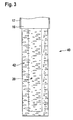
- FIG. 3 shows a second embodiment of a sensor device according to the invention, which is referenced 40 overall. This is similarly configured as the above-described with reference to Figures 1 and 2 sensor device 10, for identical components, therefore, the same reference numerals are used in Figure 3 as in Figure 1 and to avoid repetition, reference is made to the above explanations with respect to these components.
- the sensor device 40 differs by the use of a sintered filter element 42, which forms an oil-permeable casing for the sensor element 20 immersed in the filter element 42.
- the filter element 42 has a high porosity and is preferably made of metal. This makes it possible to apply an electric potential to the filter element 42 in order to retain charged particles of one polarity from the sensor element 20, as has already been explained above with reference to the metal fabrics 31, 32 and 33 of the sensor device 10.
- FIGS. 4, 5 and 6 show a third embodiment of a sensor device according to the invention, which is designated overall by the reference numeral 50.
- This comprises a housing 52 having an oil inlet 53 and an oil outlet 54, which are in fluid communication with each other via a flow path, namely an input channel 56, a downstream in the flow direction 57 to this subsequent filter chamber 58 and an output channel 59.
- a cylindrical filter element 65 is arranged with a multi-layer, for example made of nonwoven and / or filter paper filter jacket 66 which is covered on its front sides on the upper side by an upper end plate 67 and the lower side of a lower end plate 68.
- the upper end disk 67 has in the usual way a passage opening, not shown in the drawing, so that the interior of the filter element 65 surrounded by the filter casing 66 is in fluid communication with the output channel 59 via the upper end disk 67.
- the filter element 65 can be flowed through by the oil to be examined radially from outside to inside.
- the housing 52 has a sensor space 61, which is accessible via a sensor connection 62 from the outside and is connected via a passage 63 to the output channel 59 in flow communication.
- the sensor space 61 accommodates a sensor element 70 which is fixed on a carrier board 71, which in turn is held on an ultrasonic source in the form of a vibrating part 72 which can be set piezoelectrically into mechanical oscillations.
- the sensor space 61 also receives a cleaning unit 74 with a stripping element 75, for example a rubber lip or a brush strip, which rests on the sensitive surface of the sensor element 20 and coupled via a slide 77 with an actuator 78, for example a magnetic coil is. With the aid of the actuator 78, the stripping element 75 can be displaced back and forth along the surface of the sensor element 70.
- stripping member 75 is shown in solid line in a retracted position and in phantom in an extended position.
- the sensor device 50 can be integrated into an oil circuit. Via the oil inlet 53, the oil to be examined can enter the housing 52. It then flows through the filter element 65, and on the clean oil side of the filter element 65, namely downstream of the filter element 65, the oil to be tested strikes the sensor element 70, which dives via the passage 63 from the sensor chamber 61 into the output channel 59 and at least one physical or chemical property of the oil detected. Oil contaminants are largely retained by the filter element 65.
- a dirt deposit which nevertheless develops on the surface of the sensor element 70 over time can be removed by means of the cleaning unit 74 and the oscillating part 72 by mechanically vibrating the sensor element 70 together with the carrier board 71 from the oscillating part 72 and by means of the stripping element 75 Actuator 78 along the sensitive surface of the sensor element 70 is pushed back and forth to clean the sensor surface.
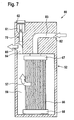
- FIG. 7 shows a further alternative embodiment of a sensor device according to the invention, which is designated overall by the reference numeral 80.
- This is largely identical to the sensor device 50 explained above with reference to FIGS. 4, 5 and 6.
- the same reference numerals are used in FIG. 7 as in FIGS. 4, 5 and 6 from repetitions to the above explanations with reference.
- the sensor device 80 differs in that the flow direction of the oil to be examined is reversed by the oil to be examined first via an oil inlet 82, an inlet channel 83 and the upper end plate 67 enters the interior of the filter element 65 and then the filter element 65 flows radially from the inside to the outside. Via an output channel 84 and an oil outlet 85, the filtered oil from the housing 52 of the sensor device 80 can emerge.
- a sensor element 70 with a support plate 71 and a vibrating part 72 is used and a cleaning unit 74 with a stripping element 75, a slider 77 and an actuator 78.
- the sensor element 70 of the sensor device 80 is as in all the preceding embodiments on the Pure oil side of the filter element 75 and therefore protected from contamination of the oil to be examined. A coating which nevertheless deposits on the surface of the sensor element 70 over the course of time can be removed in a simple manner by means of the cleaning unit 74 and the oscillating part 72, without it being necessary for this purpose to exchange the sensor element 70.
Landscapes
- Chemical & Material Sciences (AREA)
- Health & Medical Sciences (AREA)
- Engineering & Computer Science (AREA)
- Life Sciences & Earth Sciences (AREA)
- Medicinal Chemistry (AREA)
- Oil, Petroleum & Natural Gas (AREA)
- General Chemical & Material Sciences (AREA)
- Food Science & Technology (AREA)
- Chemical Kinetics & Catalysis (AREA)
- Physics & Mathematics (AREA)
- Analytical Chemistry (AREA)
- Biochemistry (AREA)
- General Health & Medical Sciences (AREA)
- General Physics & Mathematics (AREA)
- Immunology (AREA)
- Pathology (AREA)
- Investigating Or Analyzing Materials By The Use Of Electric Means (AREA)
Priority Applications (1)
| Application Number | Priority Date | Filing Date | Title |
|---|---|---|---|
| EP05027708A EP1798552A1 (fr) | 2005-12-17 | 2005-12-17 | Dispositif de détection pour huiles hydrauliques |
Applications Claiming Priority (1)
| Application Number | Priority Date | Filing Date | Title |
|---|---|---|---|
| EP05027708A EP1798552A1 (fr) | 2005-12-17 | 2005-12-17 | Dispositif de détection pour huiles hydrauliques |
Publications (1)
| Publication Number | Publication Date |
|---|---|
| EP1798552A1 true EP1798552A1 (fr) | 2007-06-20 |
Family
ID=36218224
Family Applications (1)
| Application Number | Title | Priority Date | Filing Date |
|---|---|---|---|
| EP05027708A Withdrawn EP1798552A1 (fr) | 2005-12-17 | 2005-12-17 | Dispositif de détection pour huiles hydrauliques |
Country Status (1)
| Country | Link |
|---|---|
| EP (1) | EP1798552A1 (fr) |
Citations (7)
| Publication number | Priority date | Publication date | Assignee | Title |
|---|---|---|---|---|
| JPS58144734A (ja) * | 1982-02-24 | 1983-08-29 | Nissan Motor Co Ltd | オイル劣化検知装置 |
| US4733556A (en) * | 1986-12-22 | 1988-03-29 | Ford Motor Company | Method and apparatus for sensing the condition of lubricating oil in an internal combustion engine |
| US5023133A (en) * | 1986-12-12 | 1991-06-11 | The Lubrizol Corporation | Acid sensor |
| DE10103532A1 (de) * | 2000-01-27 | 2001-08-16 | Delphi Tech Inc | Inline-Ölzustandssensor |
| US20030046985A1 (en) * | 2001-09-10 | 2003-03-13 | Honeywell International Inc. | Oil quality sensor system, method and apparatus |
| US20030179002A1 (en) * | 2002-02-27 | 2003-09-25 | Filterwerk Mann & Hummel Gmbh | Oil quality measurement device |
| WO2005040788A2 (fr) * | 2003-10-23 | 2005-05-06 | Ebro Electronic Gmbh & Co. Kg | Procede de mesure d'huiles ou de graisses, dispositif filtrant destine aux huiles ou graisses et dispositif de mesure |
-
2005
- 2005-12-17 EP EP05027708A patent/EP1798552A1/fr not_active Withdrawn
Patent Citations (7)
| Publication number | Priority date | Publication date | Assignee | Title |
|---|---|---|---|---|
| JPS58144734A (ja) * | 1982-02-24 | 1983-08-29 | Nissan Motor Co Ltd | オイル劣化検知装置 |
| US5023133A (en) * | 1986-12-12 | 1991-06-11 | The Lubrizol Corporation | Acid sensor |
| US4733556A (en) * | 1986-12-22 | 1988-03-29 | Ford Motor Company | Method and apparatus for sensing the condition of lubricating oil in an internal combustion engine |
| DE10103532A1 (de) * | 2000-01-27 | 2001-08-16 | Delphi Tech Inc | Inline-Ölzustandssensor |
| US20030046985A1 (en) * | 2001-09-10 | 2003-03-13 | Honeywell International Inc. | Oil quality sensor system, method and apparatus |
| US20030179002A1 (en) * | 2002-02-27 | 2003-09-25 | Filterwerk Mann & Hummel Gmbh | Oil quality measurement device |
| WO2005040788A2 (fr) * | 2003-10-23 | 2005-05-06 | Ebro Electronic Gmbh & Co. Kg | Procede de mesure d'huiles ou de graisses, dispositif filtrant destine aux huiles ou graisses et dispositif de mesure |
Non-Patent Citations (1)
| Title |
|---|
| PATENT ABSTRACTS OF JAPAN vol. 007, no. 262 (P - 238) 22 November 1983 (1983-11-22) * |
Similar Documents
| Publication | Publication Date | Title |
|---|---|---|
| EP1106997B1 (fr) | Procédé pour la mesure d'huile dans l'eau | |
| DE4131969C2 (de) | Schmierölüberwachungseinrichtung | |
| EP1444498A2 (fr) | Dispositif et procede de determination de la qualite d'une substance, en particulier d'un lubrifiant et/ou d'une huile de coupe | |
| DE102009048790B4 (de) | Biosensorvorrichtung mit Filterüberwachungseinrichtung | |
| DE2636406A1 (de) | Verfahren und einrichtung zur feststellung leitfaehiger partikel in einem stroemungssystem | |
| EP3207357A1 (fr) | Détecteur pour la détermination d'une concentration de particules dans un flux de gaz | |
| WO2020010372A1 (fr) | Capteur piézo-électrique comprenant une couche d'actionnement pour détecter des propriétés de fluides | |
| EP2171437A1 (fr) | Élément détecteur pour détection de particules conductrices dans un flux gazeux, procédé de production et utilisation | |
| EP3025159B1 (fr) | Carte à pointes verticale | |
| EP4300094A1 (fr) | Unité de détection pour surveiller un sorbant et filtre à sorption doté d'une unité de détection intégrée | |
| DE10345253B4 (de) | Verfahren zum Betreiben eines Zustandssensors für Flüssigkeiten | |
| EP1798552A1 (fr) | Dispositif de détection pour huiles hydrauliques | |
| WO2021078855A1 (fr) | Dispositif pour déterminer une pression s'exerçant sur une surface ou une paroi d'un corps agencé dans un canal d'écoulement ou une variation de pression dans le temps s'exerçant sur une surface ou une paroi d'un corps agencé dans un canal d'écoulement | |
| DE69700114T2 (de) | Nachweis aufschlagender Teilchen in einer Flüssigkeit mit Hochpassfilter zur Blasendiskriminierung | |
| DE102007039566A1 (de) | Sensorelement und Verfahren zur Detektion von Teilchen in einem Gasstrom sowie deren Verwendung | |
| WO2012031924A1 (fr) | Procédé pour surveiller le vieillissement d'une substance organique et système de mesure pourvu d'un condensateur | |
| DE10113778B4 (de) | Oberflächenwellenflüssigkeitssensor | |
| EP1304153B1 (fr) | Appareil de traitement d'air comprimé avec capteur capacitif | |
| DE102023121223A1 (de) | Filtergehäuse, Filtereinsatz und Filtereinheit mit Polarisationsfilter und elektrostatischem Abscheider | |
| DE102006040351A1 (de) | Sensor zur resistiven Bestimmung von Konzentrationen leitfähiger Partikel in Gasgemischen | |
| DE102014113655A1 (de) | Ventilgehäuse | |
| EP2696045A2 (fr) | Dispositif destiné à la surveillance dýun fluide hydraulique | |
| EP1943496B1 (fr) | Capteur de corrosion | |
| DE19647201C1 (de) | Vorrichtung zur Messung des Wasseranteils in einem Fluid | |
| DE10322427A1 (de) | Sensor zur Detektion von Teilchen in einem Gasstrom |
Legal Events
| Date | Code | Title | Description |
|---|---|---|---|
| PUAI | Public reference made under article 153(3) epc to a published international application that has entered the european phase |
Free format text: ORIGINAL CODE: 0009012 |
|
| AK | Designated contracting states |
Kind code of ref document: A1 Designated state(s): AT BE BG CH CY CZ DE DK EE ES FI FR GB GR HU IE IS IT LI LT LU LV MC NL PL PT RO SE SI SK TR |
|
| AX | Request for extension of the european patent |
Extension state: AL BA HR MK YU |
|
| 17P | Request for examination filed |
Effective date: 20071219 |
|
| 17Q | First examination report despatched |
Effective date: 20080128 |
|
| AKX | Designation fees paid |
Designated state(s): AT BE BG CH CY CZ DE DK EE ES FI FR GB GR HU IE IS IT LI LT LU LV MC NL PL PT RO SE SI SK TR |
|
| STAA | Information on the status of an ep patent application or granted ep patent |
Free format text: STATUS: THE APPLICATION IS DEEMED TO BE WITHDRAWN |
|
| 18D | Application deemed to be withdrawn |
Effective date: 20090407 |