EP1798573A2 - Ultraschalldiagnosesystem und Verfahren zur Darstellung des Dopplerspektrums von mehreren Probenvolumina - Google Patents
Ultraschalldiagnosesystem und Verfahren zur Darstellung des Dopplerspektrums von mehreren Probenvolumina Download PDFInfo
- Publication number
- EP1798573A2 EP1798573A2 EP06025939A EP06025939A EP1798573A2 EP 1798573 A2 EP1798573 A2 EP 1798573A2 EP 06025939 A EP06025939 A EP 06025939A EP 06025939 A EP06025939 A EP 06025939A EP 1798573 A2 EP1798573 A2 EP 1798573A2
- Authority
- EP
- European Patent Office
- Prior art keywords
- spectrum
- doppler spectrum
- aliasing
- doppler
- images
- Prior art date
- Legal status (The legal status is an assumption and is not a legal conclusion. Google has not performed a legal analysis and makes no representation as to the accuracy of the status listed.)
- Withdrawn
Links
Images








Classifications
-
- A—HUMAN NECESSITIES
- A61—MEDICAL OR VETERINARY SCIENCE; HYGIENE
- A61B—DIAGNOSIS; SURGERY; IDENTIFICATION
- A61B8/00—Diagnosis using ultrasonic, sonic or infrasonic waves
- A61B8/08—Clinical applications
-
- A—HUMAN NECESSITIES
- A61—MEDICAL OR VETERINARY SCIENCE; HYGIENE
- A61B—DIAGNOSIS; SURGERY; IDENTIFICATION
- A61B8/00—Diagnosis using ultrasonic, sonic or infrasonic waves
- A61B8/46—Ultrasonic, sonic or infrasonic diagnostic devices with special arrangements for interfacing with the operator or the patient
- A61B8/461—Displaying means of special interest
- A61B8/463—Displaying means of special interest characterised by displaying multiple images or images and diagnostic data on one display
-
- A—HUMAN NECESSITIES
- A61—MEDICAL OR VETERINARY SCIENCE; HYGIENE
- A61B—DIAGNOSIS; SURGERY; IDENTIFICATION
- A61B8/00—Diagnosis using ultrasonic, sonic or infrasonic waves
- A61B8/48—Diagnostic techniques
- A61B8/488—Diagnostic techniques involving Doppler signals
-
- G—PHYSICS
- G01—MEASURING; TESTING
- G01S—RADIO DIRECTION-FINDING; RADIO NAVIGATION; DETERMINING DISTANCE OR VELOCITY BY USE OF RADIO WAVES; LOCATING OR PRESENCE-DETECTING BY USE OF THE REFLECTION OR RERADIATION OF RADIO WAVES; ANALOGOUS ARRANGEMENTS USING OTHER WAVES
- G01S15/00—Systems using the reflection or reradiation of acoustic waves, e.g. sonar systems
- G01S15/02—Systems using the reflection or reradiation of acoustic waves, e.g. sonar systems using reflection of acoustic waves
- G01S15/50—Systems of measurement, based on relative movement of the target
- G01S15/58—Velocity or trajectory determination systems; Sense-of-movement determination systems
- G01S15/582—Velocity or trajectory determination systems; Sense-of-movement determination systems using transmission of interrupted pulse-modulated waves and based upon the Doppler effect resulting from movement of targets
- G01S15/584—Velocity or trajectory determination systems; Sense-of-movement determination systems using transmission of interrupted pulse-modulated waves and based upon the Doppler effect resulting from movement of targets with measures taken for suppressing velocity ambiguities, i.e. anti-aliasing
-
- G—PHYSICS
- G01—MEASURING; TESTING
- G01S—RADIO DIRECTION-FINDING; RADIO NAVIGATION; DETERMINING DISTANCE OR VELOCITY BY USE OF RADIO WAVES; LOCATING OR PRESENCE-DETECTING BY USE OF THE REFLECTION OR RERADIATION OF RADIO WAVES; ANALOGOUS ARRANGEMENTS USING OTHER WAVES
- G01S7/00—Details of systems according to groups G01S13/00, G01S15/00, G01S17/00
- G01S7/52—Details of systems according to groups G01S13/00, G01S15/00, G01S17/00 of systems according to group G01S15/00
- G01S7/52017—Details of systems according to groups G01S13/00, G01S15/00, G01S17/00 of systems according to group G01S15/00 particularly adapted to short-range imaging
- G01S7/52085—Details related to the ultrasound signal acquisition, e.g. scan sequences
- G01S7/52087—Details related to the ultrasound signal acquisition, e.g. scan sequences using synchronization techniques
-
- A—HUMAN NECESSITIES
- A61—MEDICAL OR VETERINARY SCIENCE; HYGIENE
- A61B—DIAGNOSIS; SURGERY; IDENTIFICATION
- A61B8/00—Diagnosis using ultrasonic, sonic or infrasonic waves
- A61B8/06—Measuring blood flow
-
- A—HUMAN NECESSITIES
- A61—MEDICAL OR VETERINARY SCIENCE; HYGIENE
- A61B—DIAGNOSIS; SURGERY; IDENTIFICATION
- A61B8/00—Diagnosis using ultrasonic, sonic or infrasonic waves
- A61B8/13—Tomography
-
- A—HUMAN NECESSITIES
- A61—MEDICAL OR VETERINARY SCIENCE; HYGIENE
- A61B—DIAGNOSIS; SURGERY; IDENTIFICATION
- A61B8/00—Diagnosis using ultrasonic, sonic or infrasonic waves
- A61B8/54—Control of the diagnostic device
- A61B8/543—Control of the diagnostic device involving acquisition triggered by a physiological signal
-
- G—PHYSICS
- G01—MEASURING; TESTING
- G01S—RADIO DIRECTION-FINDING; RADIO NAVIGATION; DETERMINING DISTANCE OR VELOCITY BY USE OF RADIO WAVES; LOCATING OR PRESENCE-DETECTING BY USE OF THE REFLECTION OR RERADIATION OF RADIO WAVES; ANALOGOUS ARRANGEMENTS USING OTHER WAVES
- G01S15/00—Systems using the reflection or reradiation of acoustic waves, e.g. sonar systems
- G01S15/88—Sonar systems specially adapted for specific applications
- G01S15/89—Sonar systems specially adapted for specific applications for mapping or imaging
- G01S15/8906—Short-range imaging systems; Acoustic microscope systems using pulse-echo techniques
- G01S15/8979—Combined Doppler and pulse-echo imaging systems
-
- G—PHYSICS
- G01—MEASURING; TESTING
- G01S—RADIO DIRECTION-FINDING; RADIO NAVIGATION; DETERMINING DISTANCE OR VELOCITY BY USE OF RADIO WAVES; LOCATING OR PRESENCE-DETECTING BY USE OF THE REFLECTION OR RERADIATION OF RADIO WAVES; ANALOGOUS ARRANGEMENTS USING OTHER WAVES
- G01S7/00—Details of systems according to groups G01S13/00, G01S15/00, G01S17/00
- G01S7/52—Details of systems according to groups G01S13/00, G01S15/00, G01S17/00 of systems according to group G01S15/00
- G01S7/52017—Details of systems according to groups G01S13/00, G01S15/00, G01S17/00 of systems according to group G01S15/00 particularly adapted to short-range imaging
- G01S7/52053—Display arrangements
- G01S7/52057—Cathode ray tube displays
- G01S7/5206—Two-dimensional coordinated display of distance and direction; B-scan display
- G01S7/52066—Time-position or time-motion displays
-
- G—PHYSICS
- G01—MEASURING; TESTING
- G01S—RADIO DIRECTION-FINDING; RADIO NAVIGATION; DETERMINING DISTANCE OR VELOCITY BY USE OF RADIO WAVES; LOCATING OR PRESENCE-DETECTING BY USE OF THE REFLECTION OR RERADIATION OF RADIO WAVES; ANALOGOUS ARRANGEMENTS USING OTHER WAVES
- G01S7/00—Details of systems according to groups G01S13/00, G01S15/00, G01S17/00
- G01S7/52—Details of systems according to groups G01S13/00, G01S15/00, G01S17/00 of systems according to group G01S15/00
- G01S7/52017—Details of systems according to groups G01S13/00, G01S15/00, G01S17/00 of systems according to group G01S15/00 particularly adapted to short-range imaging
- G01S7/52053—Display arrangements
- G01S7/52057—Cathode ray tube displays
- G01S7/52074—Composite displays, e.g. split-screen displays; Combination of multiple images or of images and alphanumeric tabular information
Definitions
- the present invention generally relates to an ultrasound diagnostic system, and more particularly to an ultrasound diagnostic system adapted to provide spectrum images of multiple sample volumes.
- An ultrasound diagnostic system has become an important and popular diagnostic tool since it has a wide range of applications. Specifically, due to its non-invasive and non-destructive nature, the ultrasound diagnostic system has been extensively used in the medical profession. Modern high-performance ultrasound diagnostic systems and techniques are commonly used to produce two or three-dimensional diagnostic images of internal features of an object (e.g., human organs).
- an object e.g., human organs
- the ultrasound diagnostic system generally uses a wide bandwidth transducer to transmit and receive ultrasound signals.
- the ultrasound diagnostic system forms images of human internal tissues by electrically exciting an acoustic transducer element or an array of acoustic transducer elements to generate ultrasound signals that travel into the body.
- the ultrasound signals produce ultrasound echo signals since they are reflected from body tissues, which appear as discontinuities to the propagating ultrasound signals.
- Various ultrasound echo signals return to the transducer element and are converted into electrical signals, which are amplified and processed to produce ultrasound data for an image of the tissues.
- the ultrasound diagnostic system is very important in the medical field since it provides physicians with real-time and high-resolution images of human internal features without the need for invasive observation techniques such as surgery.
- FIG. 1 shows an example of displaying a B-mode image and a Doppler spectrum at the same time.
- the B-mode image 11 is an image that displays the brightness, which indicates the intensities of the ultrasound signals reflected from the target object, on a screen. If a user sets a sample volume 13 on a blood vessel 12 in the B-mode image 11 by using a user input interface such as a track ball, then the ultrasound diagnostic system acquires Doppler data of the sample volume and provides a Doppler spectrum image 14 or sound corresponding to the frequency or velocity.
- FIG. 1 shows an example of displaying a B-mode image and a Doppler spectrum at the same time in accordance with the prior art
- FIG. 2 is a block diagram illustrating an ultrasound diagnostic system constructed in accordance with one embodiment of the present invention
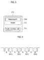
- FIG. 3 is a schematic block diagram illustrating an ultrasound diagnosis unit
- FIG. 4 is a timing diagram illustrating a waveform of a clock used to obtain a B-mode image and Doppler data of sample volumes in accordance with one embodiment of the present invention
- FIG. 5 is a diagram illustrating an example that divides transducers, which are included in a probe, in accordance with the number of sample volumes;
- FIG. 6 is a timing diagram illustrating a waveform of a clock used to obtain a B-mode image and Doppler data of sample volumes in accordance with another embodiment of the present invention
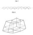
- FIG. 7 is a timing diagram illustrating a waveform of a clock used to obtain a B-mode image and Doppler data of sample volumes in accordance with yet another embodiment of the present invention.
- FIG. 8 is a schematic diagram illustrating sectional planes in ultrasound volume data
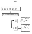
- FIG. 9 a schematic diagram illustrating a procedure for producing Doppler spectra of sample volumes
- FIG. 10 shows an example of displaying a B-mode image and Doppler spectrum images at the same time in accordance with one embodiment of the present invention
- FIG. 11 is a schematic diagram illustrating examples of spectrum models
- FIG. 12 is a schematic diagram illustrating an example of showing pixel indices, aliasing size and spectrum size
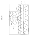
- FIG. 13 shows an example of simultaneously displaying a B-mode image and Doppler spectrum images with base lines and pulse repetition frequencies adjusted in accordance with one embodiment of the present invention
- FIG. 14 shows an example of displaying two B-mode images and Doppler spectrum images in accordance with another embodiment of the present invention.
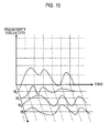
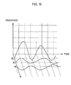
- FIGS. 15 and 16 are diagrams illustrating examples of displaying a plurality of Doppler spectrum images in accordance with the present invention.
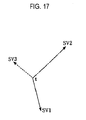
- FIG. 17 is a diagram illustrating Doppler spectra of sample volumes, which correspond to axes of a 3-dimensional graph
- FIG. 18 shows an example of displaying two B-mode images and Doppler spectrum images synchronized with ECG signals in accordance with yet another embodiment of the present invention.
- FIG. 19 shows an example of displaying a B-mode image, Doppler spectrum images synchronized with ECG signals in accordance with still another embodiment of the present invention.
- FIG. 2 is a block diagram illustrating an ultrasound diagnostic system, which is constructed in accordance with one embodiment of the present invention.
- an ultrasound diagnostic system 200 includes an ultrasound diagnosis unit 210, a user input unit 220, a processor 230, a storing unit 240, a spectrum control unit 250 and an output unit 260.
- the output unit may include an image output unit 262 and a sound output unit 264.
- the ultrasound diagnostic system 100 may further include an electrocardiogram (ECG) signal providing unit 270.
- ECG electrocardiogram
- the ultrasound diagnosis unit 210 is configured to transmit ultrasound signals to the target object and receive the ultrasound signals reflected from the target object so as to acquire ultrasound scanning information of the target object. Further, the ultrasound diagnosis unit 210 is configured to receive selection information including the locations and sizes of sample volumes designated by the user through the user input unit 220, thereby acquiring Doppler data of the designated sample volumes.
- the ultrasound diagnosis unit 210 includes: a probe 212 for transmitting the ultrasound signals to the target object and receiving the ultrasound signals reflected from the target object through a plurality of transducers 212a; and a transmission/reception control unit 214 for controlling the transmission/reception of the ultrasound signals as shown in FIG. 3.
- the probe 212 may be a multi-dimensional array probe including a plurality of transducers.
- the transmission/reception control unit 214 controls the transmission/reception of the ultrasound signals to obtain ultrasound scanning information for forming the ultrasound images, e.g., the B-mode image of the target object and Doppler data corresponding to a plurality of sample volumes designated on the B-mode image of the target object.
- the transmission/reception control unit 214 may alternately transmit/receive ultrasound signals to/from each sample volume so as to obtain the Doppler data.
- FIG. 4 is a timing diagram illustrating a waveform of a clock used for repeatedly performing a first ultrasound transmission/reception process (B) to obtain a B-mode image and a second ultrasound transmission/reception process (D1, D2) to obtain the Doppler data of the sample volumes. In such a case, the second ultrasound transmission/reception process is alternately carried out for the sample volumes SV1 and SV2.
- the transmission/reception control unit 214 is configured to transmit ultrasound signals to a plurality of sample volumes and receive the ultrasound signals reflected from the sample volumes at the same time.
- the transducers 212a may be divided into several groups in accordance with the number of the sample volumes.
- the transmission/reception control unit 214 controls the transducer groups Tsv1- Tsvn.
- the first ultrasound transmission/reception process (D1) and the second ultrasound transmission/reception process (D2) are alternately executed in synchronization with a clock cycle, as shown in FIG. 6.
- the ultrasound signals may be simultaneously transmitted to the sample volumes SV1 and SV2 in the second ultrasound transmission/reception process.
- the transmission/reception control unit 214 is configured to transmit ultrasound signals to obtain various types of ultrasound images.
- a B-mode image and a color flow image may be displayed on the screen at the same time.
- the ultrasound transmission/reception processes are alternately executed in synchronization with a clock cycle as shown in FIG. 7. That is, the ultrasound transmission/reception process for obtaining the B-mode image B, the color flow image C and Doppler spectrum images D1 and D2 are alternately and repeatedly carried out.
- the sample volumes SV1 and SV2 may be set on the color flow image.
- the ultrasound signals may be simultaneously transmitted to the sample volumes SV1 and SV2 for obtaining the Doppler spectrum images D1 and D2.
- the user input unit 220 allows a user to input selection information indicating the locations and sizes of the sample volumes on the B-mode image of the target object. Also, the user input unit 220 receives inputs related to the conditions for displaying a Doppler spectrum of each sample volume such as tissue Doppler spectrum or general Doppler spectrum from the user. The conditions may include baseline, scale, filter value and the like. Further, the input selection information may include color box information for setting a color box, in which the color flow image is displayed, on the B-mode image. Also, the input selection information may include information for selecting sectional planes A, B and C in volume data of the target object for obtaining the B-mode image of the target object as shown in FIG. 8.
- the processor 230 forms B-mode ultrasound image signals based on the ultrasound scanning information of the target object, which are inputted from the ultrasound diagnosis unit 210. Also, the processor 230 produces Doppler spectrum signals and Doppler sound signals based on the user selection information inputted through the user input unit 220 and the Doppler data.
- the Doppler spectrum signals include information related to the velocity, frequency or pressure change according to the time change.
- the processor 230 classifies the Doppler data of the plurality of sample volumes, which are inputted from the ultrasound diagnosis unit 210, and applies fast Fourier transformation (FFT) to the classified Doppler data of the sample volumes SV1 and SV2 so as to form the Doppler spectrum signals.
- FFT fast Fourier transformation
- the processor 230 may provide the tissue Doppler spectrum or the general Doppler spectrum for the sample volumes at the user's requests, which are inputted through the user input unit 220.
- the user's request may include base line information and pulse repetition frequency (PRF) information.
- PRF pulse repetition frequency
- the processor 230 forms at least one B-mode image based on the B-mode image signals and a plurality of Doppler spectrum images based on the Doppler spectrum signals.
- FIG. 10 shows an example of displaying the B-mode image and Doppler spectrum image at the same time on a screen of the image output unit 262 in accordance with one embodiment of the present invention.
- the B-mode image 1012 is displayed on a first display region 1010.
- the Doppler spectrum images 1022 and 1032 corresponding to the sample volumes SV1 and SV2, which are classified in the processor 230 are displayed on second and third displayed regions 1020 and 1030 of the image output unit 262, respectively.
- the processor 230 may provide Doppler spectrum signals, which are synchronized with an ECG signal inputted from the ECG signal providing unit 270. Also, the processor 230 may provide not only the frequency or velocity change according to the time change, but also the maximum velocity, peak gradient, velocity-time integration, mean velocity, acceleration time, deceleration time, peak systolic velocity (PSV), end diastolic velocity (EDV), resistive index (RI), pulse index (PI), systole/diastole ratio, pressure gradient and heart beating rate.
- PSV peak systolic velocity
- EDV end diastolic velocity
- RI resistive index
- PI pulse index
- the storing unit 240 temporarily stores the B-mode ultrasound image signals and the Doppler spectrum signals received from the processor 230. Further, the storing unit 240 stores a plurality of spectrum models SM11 to SM35 showing the types of Doppler spectra as illustrated in FIG. 11. Also, the storing unit 240 stores an aliasing size of the Doppler spectrum, a spectrum size and information of aliasing levels and spectrum levels.
- the aliasing size represents the number of aliasing pixels (APs) in the Doppler spectrum image and the spectrum size represents the number of pixels corresponding to a height of Doppler spectrum (hereinafter referred to as the number of spectrum pixels (SPs)), in which the aliasing is not generated, with reference to a base line.
- the aliasing levels and the spectrum levels are determined based on the numbers of APs and SPs, and may be stored in the storing unit 240 as the following tables.
- the spectrum control unit 250 acquires Doppler spectrum images of each sample volume based on the Doppler spectrum signals stored in the storing unit 240.
- the spectrum control unit 250 analyzes the Doppler spectrum images based on the plurality of spectrum models SM11 to SM35 stored in the storing unit 240, thereby determining spectrum models corresponding to the Doppler spectrum images.
- the spectrum control unit 250 In order to determine the spectrum models corresponding to the Doppler spectrum images of each sample volume, the spectrum control unit 250 detects an intensity of each pixel consisting of the Doppler spectrum images and compares the detected intensity of each pixel with a first threshold. If the pixel intensity is greater than the first threshold, then the spectrum control unit 250 determines the corresponding pixel as a contour pixel of the Doppler spectrum image. After detecting the contour of the Doppler spectrum image, the spectrum control unit 250 determines the spectrum models corresponding to the Doppler spectrum images based on the detected contours.
- the spectrum control unit 250 sets pixel indices (PI) on the pixels existing in the same column of each Doppler spectrum image. For example, the spectrum control unit 250 sets PI on the Doppler spectrum images corresponding to sample volumes SV1 and SV2, respectively, as shown in FIG. 12.
- the spectrum control unit 250 analyzes pixels of the Doppler spectrum images corresponding to PIs to check whether the aliasing is generated. If it is determined that the aliasing is generated, then the spectrum control unit 250 calculates the number of APs at each column of the Doppler spectrum image, in which the aliasing is generated, and then detects a maximum number of APs of each Doppler spectrum image.
- the spectrum control unit 250 detects PIs corresponding to the base lines of each Doppler spectrum image, in which the aliasing is generated.
- the spectrum control unit 152 checks whether the aliasing can be removed by adjusting the base line based on the PI of the base line and the maximum PI. If it is determined that the aliasing can be removed by adjusting the base line, then the spectrum control unit 152 adjusts the base line of the corresponding Doppler spectrum image by referencing the detected PI of the base line and the maximum PI.
- the spectrum control unit 250 determines an aliasing level corresponding to the maximum number of APs of the Doppler spectrum image by referencing information (Table 1) stored in the storing unit 240.
- the spectrum control unit 250 adjusts PRF for the corresponding sampling volume based on the detected aliasing level.
- the spectrum control unit 250 sets the increment of PRF differently according to the aliasing level.
- the spectrum control unit increases PRF based on an increment of PRF determined by the aliasing level, thereby obtaining a Doppler spectrum image 1022a with the aliasing removed from the Doppler spectrum image 1022 as shown in FIG. 13.
- the spectrum control unit 250 calculates the number of SPs of each column in the Doppler spectrum images, in which the aliasing is not generated, based on PI and then detects a maximum SP of each Doppler spectrum image.
- the spectrum control unit 250 determines a spectrum level corresponding to the maximum SP by referencing information (Table 2) stored in the storing unit 240.
- the spectrum control unit 250 checks whether the spectrum level is less than a second threshold for adjusting PRF. If it is determined that the spectrum level is greater than the second threshold, then the PRF is not adjusted.
- the spectrum control unit 250 adjusts PRF for the sample volume of the Doppler spectrum image in which the aliasing is not generated. For example, if the spectrum level is less than 3, then the spectrum control unit 250 may decrease PRF, thereby obtaining a Doppler spectrum image 1032a adjusting PRF of the Doppler spectrum image 1032 as shown in FIG. 13.
- the output unit 260 includes an image output unit 262 and a sound output unit 264.
- the image output unit 262 displays the B-mode image, Doppler spectrum and ECG waveform by receiving the B-mode image signals, Doppler spectrum signals and ECG signals from the processor 230.
- the image output unit 262 may display a plurality of the B-mode images, wherein each B-mode image is obtained from different sectional planes in the ultrasound volume data of the target object based on the input selection information inputted in the user input unit 220 as shown in FIG. 14.
- a first B-mode image 1110 and a second B-mode image 1120 which are obtained from different section planes, e.g., A and B sectional planes shown in FIG. 8, are displayed on first and second display regions 1410 and 1420 of the image output unit 262, respectively.
- the first sample volume SV1 may be set on the first B-mode image 1412 and the second sample volume SV2 may be set on the second B-mode image 1414.
- Doppler spectrum image may be displayed.
- spectrum images corresponding to a plurality of sample volumes SV0, SV1, SV2 ... may be displayed on the image display unit 262 at the same time, as shown in Figs. 15 and 16.
- the Doppler spectrum images shown in FIG. 15 represent the frequency (or velocity) changes of the sample volumes with time (t)
- the Doppler spectrum images shown in FIG. 12 represent the pressure changes of the sample volumes with time (t).
- the Doppler spectrum images shown in Figs. 15 and 16 may be displayed together with the B-mode image.
- FIG. 17 is a diagram showing Doppler spectra of the sample volumes, which correspond to each axis of a 3-dimensional graph.
- FIG. 18 is a diagram showing an example displaying Doppler spectrum images 1432 and 1442 of two sample volumes SV1 and SV2 designated by the user together with an ECG waveform 1452 displayed on a fifth display region 1450 of the image output unit 262.
- the Doppler spectrum images 1432 and 1442 show the frequency (or velocity) changes with time.
- the time difference between PSV and EDV detected from the Doppler spectra of the sample volumes can be easily recognized in real time as shown in FIG. 19.
- an example directed to simultaneously displaying the Doppler spectra of the sample volumes on a single screen is disclosed in accordance with one embodiment of the present invention.
- the Doppler spectra of the sample volumes may be separately displayed on different screens.
- the sound output unit 264 includes a plurality of speakers.
- SND represents a final sound output
- a represents a synthesis coefficient
- SND SV1 and SND SV2 represent sound components corresponding to the sample volumes.
- the ultrasound diagnostic system can individually adjust the sizes, baselines, scales and filter values of at least two different sample volumes.
- the spectrum change representing the frequency change or velocity change within a specific period of the ECG signal can be provided with numerical values.
- the peak and mean traces can be measured on the Doppler spectra of the sample volumes. Further, the time difference of a specific event between the two sample volumes can be measured.
- the Doppler spectra and the sounds of the sample volumes designated at different places on the ultrasound image can be provided at the same time. Further, the base line and the PRF of the Doppler spectrum images corresponding to the sample volumes set on the B-mode image are automatically adjusted in accordance with one embodiment of the present invention. Thus, the aliasing can be easily removed from the Doppler spectrum image.
- an ultrasound diagnostic system including: an ultrasound diagnosis unit for transmitting ultrasound signals to a target object and receiving ultrasound echo signals to acquire B-mode image signals and Doppler spectrum image signals; a processor for forming at least one B-mode image based on the B-mode image signals and forming a plurality of Doppler spectrum images for a plurality of sample volumes designated on the B-mode image based on the Doppler spectrum image signals; a user input unit for allowing a user to input selection information indicating locations and sizes of the plurality of sample volumes; and an image display unit for displaying at least one B-mode image and the plurality of Doppler spectrum images.
- a method of forming ultrasound images including: a) forming at least one B-mode image of a target object; b) setting a plurality of sample volumes on the B-mode image; c) forming Doppler spectrum images corresponding to each of the plurality of sample volumes; and d) displaying the B-mode images together with the Doppler spectrum images.
- any reference in this specification to "one embodiment,” “an embodiment,” “example embodiment,” etc. means that a particular feature, structure or characteristic described in connection with the embodiment is included in at least one embodiment of the invention.
- the appearances of such phrases in various places in the specification are not necessarily all referring to the same embodiment.
Landscapes
- Life Sciences & Earth Sciences (AREA)
- Health & Medical Sciences (AREA)
- Engineering & Computer Science (AREA)
- Physics & Mathematics (AREA)
- Biophysics (AREA)
- Radiology & Medical Imaging (AREA)
- Heart & Thoracic Surgery (AREA)
- Veterinary Medicine (AREA)
- Radar, Positioning & Navigation (AREA)
- Remote Sensing (AREA)
- Nuclear Medicine, Radiotherapy & Molecular Imaging (AREA)
- Pathology (AREA)
- Public Health (AREA)
- Biomedical Technology (AREA)
- General Health & Medical Sciences (AREA)
- Medical Informatics (AREA)
- Molecular Biology (AREA)
- Surgery (AREA)
- Animal Behavior & Ethology (AREA)
- Computer Networks & Wireless Communication (AREA)
- General Physics & Mathematics (AREA)
- Physiology (AREA)
- Acoustics & Sound (AREA)
- Ultra Sonic Daignosis Equipment (AREA)
Applications Claiming Priority (4)
| Application Number | Priority Date | Filing Date | Title |
|---|---|---|---|
| KR20050124792 | 2005-12-16 | ||
| KR1020060069974A KR100880399B1 (ko) | 2006-07-25 | 2006-07-25 | 초음파 영상을 형성하는 초음파 시스템 및 방법 |
| KR1020060072111A KR100879916B1 (ko) | 2006-07-31 | 2006-07-31 | 초음파 영상을 형성하는 초음파 시스템 및 방법 |
| KR1020060080562A KR100884248B1 (ko) | 2006-08-24 | 2006-08-24 | 초음파 영상을 형성하는 초음파 시스템 및 방법 |
Publications (2)
| Publication Number | Publication Date |
|---|---|
| EP1798573A2 true EP1798573A2 (de) | 2007-06-20 |
| EP1798573A3 EP1798573A3 (de) | 2009-09-09 |
Family
ID=37907928
Family Applications (1)
| Application Number | Title | Priority Date | Filing Date |
|---|---|---|---|
| EP06025939A Withdrawn EP1798573A3 (de) | 2005-12-16 | 2006-12-14 | Ultraschalldiagnosesystem und Verfahren zur Darstellung des Dopplerspektrums von mehreren Probenvolumina |
Country Status (3)
| Country | Link |
|---|---|
| US (2) | US7798964B2 (de) |
| EP (1) | EP1798573A3 (de) |
| JP (1) | JP2007160120A (de) |
Cited By (7)
| Publication number | Priority date | Publication date | Assignee | Title |
|---|---|---|---|---|
| CN103181782A (zh) * | 2011-12-29 | 2013-07-03 | 三星麦迪森株式会社 | 超声系统和提供多普勒频谱图像的方法 |
| EP2740408A1 (de) * | 2012-12-07 | 2014-06-11 | Samsung Medison Co., Ltd. | Ultraschalldiagnoseverfahren und Ultraschalldiagnosevorrichtung mit Volumendaten |
| EP2989992A1 (de) * | 2014-09-01 | 2016-03-02 | Samsung Medison Co., Ltd. | Medizinische bildgebungsvorrichtung und verfahren zur erzeugung medizinischer bilder |
| EP3005947A4 (de) * | 2013-05-27 | 2017-02-08 | Hitachi, Ltd. | Ultraschall-bildaufnahmevorrichtung und ultraschall-bildaufnahmeverfahren |
| WO2017033098A1 (en) * | 2015-08-27 | 2017-03-02 | Koninklijke Philips N.V. | Spectral doppler processing with adaptive sample window size |
| CN116957946A (zh) * | 2022-04-14 | 2023-10-27 | 武汉联影医疗科技有限公司 | 图像处理方法、装置、计算机设备、存储介质和程序产品 |
| US12437407B2 (en) | 2022-03-31 | 2025-10-07 | Wuhan United Imaging Healthcare Co., Ltd. | Methods and systems for ultrasound image processing |
Families Citing this family (25)
| Publication number | Priority date | Publication date | Assignee | Title |
|---|---|---|---|---|
| US20080208061A1 (en) * | 2007-02-23 | 2008-08-28 | General Electric Company | Methods and systems for spatial compounding in a handheld ultrasound device |
| KR100961854B1 (ko) * | 2007-03-16 | 2010-06-09 | 주식회사 메디슨 | 도플러 스펙트럼 영상을 디스플레이하기 위한 초음파 진단시스템 및 방법 |
| KR100969536B1 (ko) * | 2007-04-06 | 2010-07-12 | 주식회사 메디슨 | 초음파 영상을 형성하는 초음파 시스템 및 방법 |
| JP5025400B2 (ja) * | 2007-09-28 | 2012-09-12 | 株式会社東芝 | 超音波診断装置、及び超音波画像処理装置 |
| US20090149755A1 (en) * | 2007-12-05 | 2009-06-11 | Medison Co., Ltd. | Ultrasound system and method of forming an ultrasound image |
| JP5100343B2 (ja) * | 2007-12-05 | 2012-12-19 | 株式会社東芝 | 超音波診断装置、及び超音波診断装置の制御プログラム |
| KR101501513B1 (ko) * | 2008-01-04 | 2015-03-11 | 삼성메디슨 주식회사 | 초음파 영상을 형성하는 초음파 시스템 및 방법 |
| WO2010131136A1 (en) | 2009-05-13 | 2010-11-18 | Koninklijke Philips Electronics, N.V. | Ultrasonic blood flow doppler audio with pitch shifting |
| KR100977367B1 (ko) * | 2009-10-28 | 2010-08-20 | (주)메디슨 | 3차원 pw 스펙트럼 초음파 진단 장치 및 3차원 pw 스펙트럼 데이터 생성 방법 |
| KR101182934B1 (ko) * | 2009-12-11 | 2012-09-13 | 삼성메디슨 주식회사 | 도플러 사운드를 제공하는 초음파 시스템 및 방법 |
| KR101097578B1 (ko) * | 2010-10-08 | 2011-12-26 | 삼성메디슨 주식회사 | 3차원 컬러 도플러 영상 제공 방법 및 그를 위한 초음파 시스템 |
| CN102686164B (zh) * | 2010-12-16 | 2015-03-11 | 株式会社东芝 | 超声波诊断装置及其控制方法 |
| KR101348770B1 (ko) | 2011-12-28 | 2014-01-07 | 삼성메디슨 주식회사 | 도플러 스펙트럼 영상의 합성 영상을 제공하는 초음파 시스템 및 방법 |
| KR101368750B1 (ko) * | 2012-01-16 | 2014-02-28 | 삼성메디슨 주식회사 | 복수의 도플러 영상 제공 방법 및 복수의 도플러 영상 제공 장치 |
| JP6391912B2 (ja) * | 2013-02-26 | 2018-09-19 | キヤノンメディカルシステムズ株式会社 | 超音波診断装置 |
| KR101792591B1 (ko) | 2014-09-01 | 2017-11-01 | 삼성메디슨 주식회사 | 의료 영상 장치 및 의료 영상 생성 방법 |
| KR102462391B1 (ko) * | 2015-01-29 | 2022-11-03 | 삼성메디슨 주식회사 | 초음파 장치 및 그 동작 방법 |
| JP6411969B2 (ja) * | 2015-08-17 | 2018-10-24 | 富士フイルム株式会社 | 超音波診断装置およびドプラ波形画像生成方法 |
| CN107949331B (zh) * | 2016-06-30 | 2021-04-13 | 深圳迈瑞生物医疗电子股份有限公司 | 超声流体频谱多普勒成像方法和系统 |
| CN106236148B (zh) * | 2016-07-29 | 2019-06-28 | 飞依诺科技(苏州)有限公司 | 一种脉冲重复频率确定方法及装置 |
| KR102439767B1 (ko) * | 2016-09-20 | 2022-09-05 | 삼성메디슨 주식회사 | 초음파 영상 장치 및 초음파 영상 표시 방법 |
| US20190216430A1 (en) * | 2018-01-15 | 2019-07-18 | General Electric Company | System and method for ultrasound flow imaging |
| JP7440318B2 (ja) * | 2020-03-26 | 2024-02-28 | 日本光電工業株式会社 | 生体情報モニタ、生体情報表示方法、及びプログラム |
| CN116074410B (zh) * | 2023-01-18 | 2024-09-20 | 南京科进实业有限公司 | 一种多深度超声经颅多普勒数据动态分配方法 |
| CN116380714B (zh) * | 2023-03-15 | 2023-09-22 | 中国科学院地理科学与资源研究所 | 一种水样含沙量测量装置及使用其的测量方法 |
Citations (3)
| Publication number | Priority date | Publication date | Assignee | Title |
|---|---|---|---|---|
| US5615680A (en) | 1994-07-22 | 1997-04-01 | Kabushiki Kaisha Toshiba | Method of imaging in ultrasound diagnosis and diagnostic ultrasound system |
| EP1016880A2 (de) | 1998-12-31 | 2000-07-05 | General Electric Company | Automatische Regelung des Geschwindigkeitsgrads und Pulsfolgefrequenz für Doppler- Ultraschall- Spektrogramme |
| WO2003019227A1 (en) | 2001-08-28 | 2003-03-06 | Koninklijke Philips Electronics N.V. | Automatic optimization of doppler display parameters |
Family Cites Families (27)
| Publication number | Priority date | Publication date | Assignee | Title |
|---|---|---|---|---|
| JPH0475645A (ja) * | 1990-07-19 | 1992-03-10 | Toshiba Corp | 超音波診断装置 |
| JP2863624B2 (ja) * | 1990-11-13 | 1999-03-03 | 株式会社東芝 | 超音波診断装置 |
| US5622174A (en) * | 1992-10-02 | 1997-04-22 | Kabushiki Kaisha Toshiba | Ultrasonic diagnosis apparatus and image displaying system |
| JPH06277218A (ja) * | 1993-03-30 | 1994-10-04 | Shimadzu Corp | 超音波診断装置 |
| US5365929A (en) * | 1993-10-04 | 1994-11-22 | Advanced Technology Laboratories, Inc. | Multiple sample volume spectral Doppler |
| JP3844799B2 (ja) * | 1994-07-22 | 2006-11-15 | 株式会社東芝 | 超音波診断装置、超音波診断用のデータ処理方法、及びプログラム |
| US6569101B2 (en) * | 2001-04-19 | 2003-05-27 | Sonosite, Inc. | Medical diagnostic ultrasound instrument with ECG module, authorization mechanism and methods of use |
| JPH10165400A (ja) * | 1996-12-12 | 1998-06-23 | Furuno Electric Co Ltd | 超音波診断装置 |
| JPH1156848A (ja) | 1997-06-12 | 1999-03-02 | Aloka Co Ltd | 超音波診断装置およびその制御方法 |
| US6162176A (en) * | 1998-12-31 | 2000-12-19 | General Electric Company | Ultrasound color flow display optimization |
| JP2001046372A (ja) | 1999-08-12 | 2001-02-20 | Toshiba Corp | 超音波画像表示装置 |
| JP2001170051A (ja) | 1999-12-15 | 2001-06-26 | Aloka Co Ltd | 超音波診断装置 |
| US6592521B1 (en) * | 2000-03-01 | 2003-07-15 | Acuson Corporation | Medical diagnostic ultrasound system and method for power control |
| US6450959B1 (en) * | 2000-03-23 | 2002-09-17 | Ge Medical Systems Global Technology Company | Ultrasound B-mode and doppler flow imaging |
| JP2001299761A (ja) | 2000-04-18 | 2001-10-30 | Toshiba Corp | 超音波画像診断装置およびその制御方法 |
| JP2002000606A (ja) | 2000-06-20 | 2002-01-08 | Aloka Co Ltd | 超音波ドプラ診断装置 |
| JP2002065670A (ja) * | 2000-08-25 | 2002-03-05 | Hitachi Medical Corp | 超音波診断装置及び超音波診断画像の形成方法 |
| US6592522B2 (en) * | 2001-06-12 | 2003-07-15 | Ge Medical Systems Global Technology Company, Llc | Ultrasound display of displacement |
| JP5143984B2 (ja) | 2001-08-17 | 2013-02-13 | 日立アロカメディカル株式会社 | 超音波診断装置 |
| JP2003065675A (ja) * | 2001-08-27 | 2003-03-05 | Soyu Kankyo Kaihatsu:Kk | 有機物連続乾燥機 |
| US6663566B2 (en) * | 2002-02-19 | 2003-12-16 | Ge Medical Systems Global Technology Company, Llc | Method and apparatus for automatic control of spectral doppler imaging |
| KR100459616B1 (ko) * | 2002-04-17 | 2004-12-04 | 주식회사 메디슨 | 도플러 효과를 이용하여 인체 조직 속도를 측정하기 위한초음파 진단 장치 및 방법 |
| US7211045B2 (en) * | 2002-07-22 | 2007-05-01 | Ep Medsystems, Inc. | Method and system for using ultrasound in cardiac diagnosis and therapy |
| JP4176447B2 (ja) | 2002-10-23 | 2008-11-05 | 三菱重工業株式会社 | 燃料電池 |
| JP4099437B2 (ja) * | 2003-08-19 | 2008-06-11 | ジーイー・メディカル・システムズ・グローバル・テクノロジー・カンパニー・エルエルシー | 血流イメージング装置および超音波診断装置 |
| KR20060124824A (ko) | 2005-05-26 | 2006-12-06 | 주식회사 메디슨 | 초음파 스펙트럼 영상을 처리하는 방법 및 초음파 진단시스템 |
| KR100947826B1 (ko) | 2006-05-24 | 2010-03-18 | 주식회사 메디슨 | 초음파 영상을 디스플레이 하는 장치 및 방법 |
-
2006
- 2006-12-14 EP EP06025939A patent/EP1798573A3/de not_active Withdrawn
- 2006-12-15 JP JP2006338905A patent/JP2007160120A/ja active Pending
- 2006-12-15 US US11/611,502 patent/US7798964B2/en active Active
-
2010
- 2010-07-21 US US12/840,825 patent/US8353835B2/en active Active
Patent Citations (3)
| Publication number | Priority date | Publication date | Assignee | Title |
|---|---|---|---|---|
| US5615680A (en) | 1994-07-22 | 1997-04-01 | Kabushiki Kaisha Toshiba | Method of imaging in ultrasound diagnosis and diagnostic ultrasound system |
| EP1016880A2 (de) | 1998-12-31 | 2000-07-05 | General Electric Company | Automatische Regelung des Geschwindigkeitsgrads und Pulsfolgefrequenz für Doppler- Ultraschall- Spektrogramme |
| WO2003019227A1 (en) | 2001-08-28 | 2003-03-06 | Koninklijke Philips Electronics N.V. | Automatic optimization of doppler display parameters |
Cited By (12)
| Publication number | Priority date | Publication date | Assignee | Title |
|---|---|---|---|---|
| CN103181782A (zh) * | 2011-12-29 | 2013-07-03 | 三星麦迪森株式会社 | 超声系统和提供多普勒频谱图像的方法 |
| EP2610635A3 (de) * | 2011-12-29 | 2015-01-07 | Samsung Medison Co., Ltd. | Erstellung von spektralen Doppler Bildern, die mindestens zwei Probenvolumen entsprechen |
| EP2740408A1 (de) * | 2012-12-07 | 2014-06-11 | Samsung Medison Co., Ltd. | Ultraschalldiagnoseverfahren und Ultraschalldiagnosevorrichtung mit Volumendaten |
| CN103860195A (zh) * | 2012-12-07 | 2014-06-18 | 三星麦迪森株式会社 | 使用体数据的超声诊断方法和超声诊断设备 |
| US9307955B2 (en) | 2012-12-07 | 2016-04-12 | Samsung Medison Co., Ltd. | Ultrasound diagnostic method and ultrasound diagnostic apparatus using volume data |
| CN103860195B (zh) * | 2012-12-07 | 2018-11-02 | 三星麦迪森株式会社 | 使用体数据的超声诊断方法和超声诊断设备 |
| EP3005947A4 (de) * | 2013-05-27 | 2017-02-08 | Hitachi, Ltd. | Ultraschall-bildaufnahmevorrichtung und ultraschall-bildaufnahmeverfahren |
| EP2989992A1 (de) * | 2014-09-01 | 2016-03-02 | Samsung Medison Co., Ltd. | Medizinische bildgebungsvorrichtung und verfahren zur erzeugung medizinischer bilder |
| US11291429B2 (en) | 2014-09-01 | 2022-04-05 | Samsung Medison Co., Ltd. | Medical imaging apparatus and method of generating medical image |
| WO2017033098A1 (en) * | 2015-08-27 | 2017-03-02 | Koninklijke Philips N.V. | Spectral doppler processing with adaptive sample window size |
| US12437407B2 (en) | 2022-03-31 | 2025-10-07 | Wuhan United Imaging Healthcare Co., Ltd. | Methods and systems for ultrasound image processing |
| CN116957946A (zh) * | 2022-04-14 | 2023-10-27 | 武汉联影医疗科技有限公司 | 图像处理方法、装置、计算机设备、存储介质和程序产品 |
Also Published As
| Publication number | Publication date |
|---|---|
| US8353835B2 (en) | 2013-01-15 |
| EP1798573A3 (de) | 2009-09-09 |
| US20100286523A1 (en) | 2010-11-11 |
| US20070167790A1 (en) | 2007-07-19 |
| JP2007160120A (ja) | 2007-06-28 |
| US7798964B2 (en) | 2010-09-21 |
Similar Documents
| Publication | Publication Date | Title |
|---|---|---|
| EP1798573A2 (de) | Ultraschalldiagnosesystem und Verfahren zur Darstellung des Dopplerspektrums von mehreren Probenvolumina | |
| CN100430025C (zh) | 超声波诊断装置和图象处理装置 | |
| US7175598B2 (en) | Ultrasound diagnosis apparatus that adjusts a time phase between a plurality of image series | |
| CN112839590B (zh) | 用于确定补充超声视图的方法和系统 | |
| US7588538B2 (en) | Ultrasonic diagnostic equipment and image processing apparatus | |
| JP2003515423A (ja) | 動脈区分の複合画像列を表示する超音波画像処理方法及びシステム | |
| JP7371105B2 (ja) | 血管特性を調査するための方法及びシステム | |
| US20100312110A1 (en) | Ultrasonograph | |
| EP1932478A1 (de) | Ultraschalldiagnosesystem und Verfahren zur Anzeige mehrerer Wachstumstrenddiagramme | |
| US8715191B2 (en) | Doppler based flow measurements | |
| EP1795129B1 (de) | Vorrichtung und Verfahren zum Anzeigen eines Ultraschallbildes | |
| US6913574B2 (en) | Method and apparatus for measuring elastic characteristics of a medium by using ultrasound images | |
| KR100874550B1 (ko) | 다수의 샘플볼륨의 도플러 스펙트럼을 제공하는 초음파시스템 | |
| EP1806594A2 (de) | Ultraschall-System und Verfahren zum Anzeigen von Ultraschallbildern | |
| US20060079783A1 (en) | Method and system for deriving a fetal heart rate without the use of an electrocardiogram in non-3D imaging applications | |
| KR100879916B1 (ko) | 초음파 영상을 형성하는 초음파 시스템 및 방법 | |
| KR100880399B1 (ko) | 초음파 영상을 형성하는 초음파 시스템 및 방법 | |
| KR100884248B1 (ko) | 초음파 영상을 형성하는 초음파 시스템 및 방법 | |
| EP1250889A1 (de) | Diagnostische Ultraschallvorrichtung und Verfahren der Messung eines Indizes zur Anzeige des Gefässzustandes | |
| JP3534667B2 (ja) | 超音波計測装置 | |
| JP7457566B2 (ja) | 超音波診断装置、臍帯長測定方法及びプログラム | |
| KR100842234B1 (ko) | 도플러 스펙트럼의 베이스라인 및 스케일을 조절하는 영상처리 시스템 및 방법 | |
| WO2026037623A1 (en) | Systems and methods for automatic motion-mode switching for fetal heart rate determination | |
| KR20200107494A (ko) | 초음파 영상장치 및 그 제어방법 | |
| JP2020014595A (ja) | 超音波診断装置 |
Legal Events
| Date | Code | Title | Description |
|---|---|---|---|
| PUAI | Public reference made under article 153(3) epc to a published international application that has entered the european phase |
Free format text: ORIGINAL CODE: 0009012 |
|
| AK | Designated contracting states |
Kind code of ref document: A2 Designated state(s): AT BE BG CH CY CZ DE DK EE ES FI FR GB GR HU IE IS IT LI LT LU LV MC NL PL PT RO SE SI SK TR |
|
| AX | Request for extension of the european patent |
Extension state: AL BA HR MK YU |
|
| PUAL | Search report despatched |
Free format text: ORIGINAL CODE: 0009013 |
|
| AK | Designated contracting states |
Kind code of ref document: A3 Designated state(s): AT BE BG CH CY CZ DE DK EE ES FI FR GB GR HU IE IS IT LI LT LU LV MC NL PL PT RO SE SI SK TR |
|
| AX | Request for extension of the european patent |
Extension state: AL BA HR MK RS |
|
| 17P | Request for examination filed |
Effective date: 20100210 |
|
| 17Q | First examination report despatched |
Effective date: 20100305 |
|
| AKX | Designation fees paid |
Designated state(s): DE FR IT |
|
| STAA | Information on the status of an ep patent application or granted ep patent |
Free format text: STATUS: THE APPLICATION IS DEEMED TO BE WITHDRAWN |
|
| 18D | Application deemed to be withdrawn |
Effective date: 20131116 |